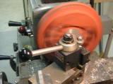
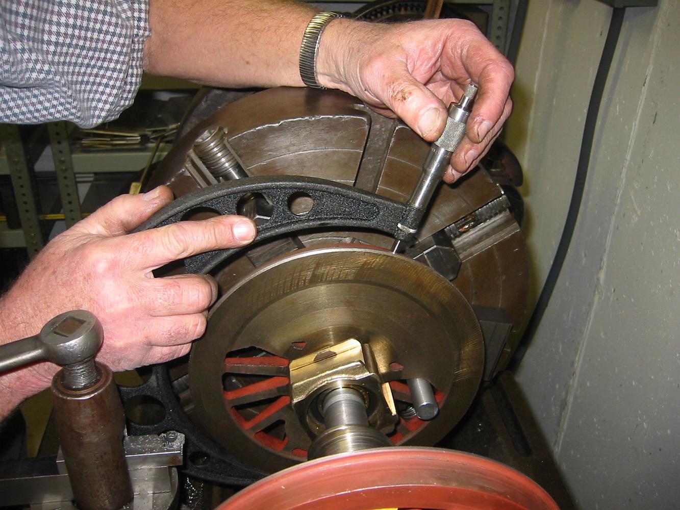
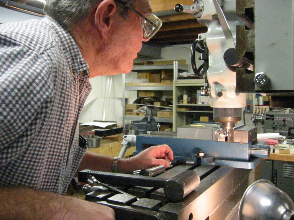
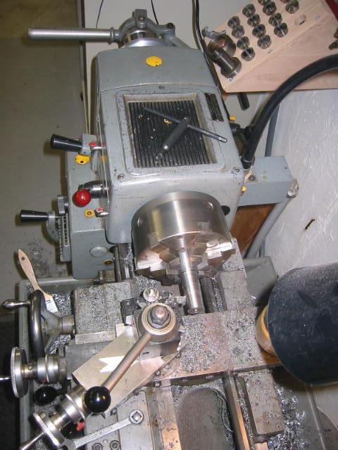
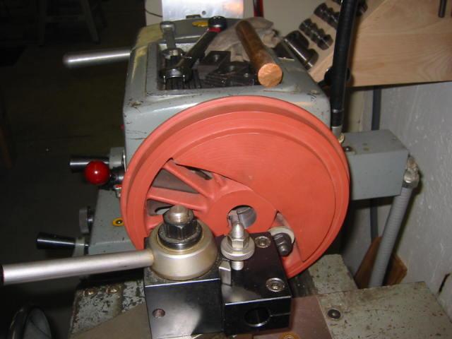
10-Aug-05 We barely had room to swing the offset wheel around without hitting the lathe ways.
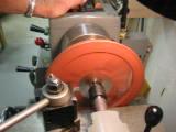
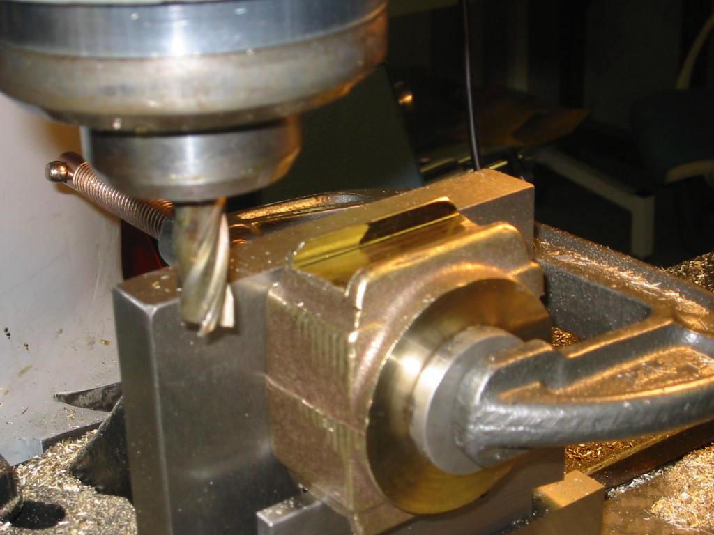
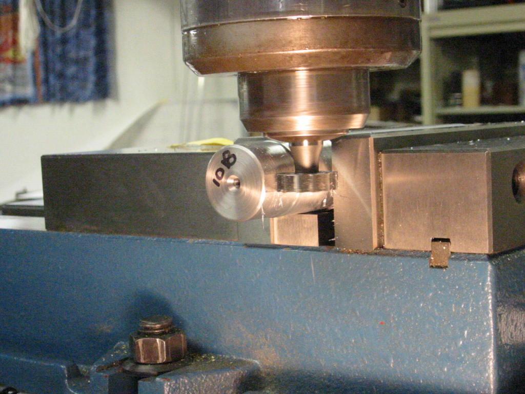
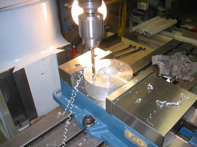
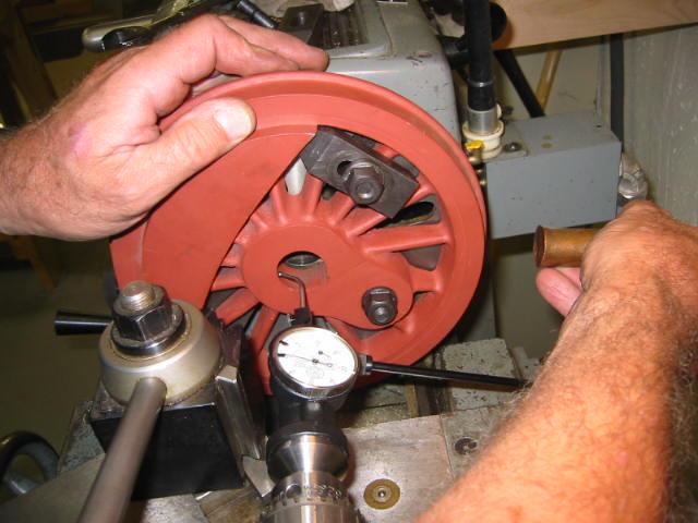
Boring the crankpin holes using the automatic downfeed.
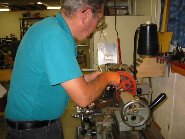
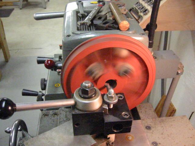
13-Jul-06 Here's what is sounded like machining the wheel with all the spokes.
While the motor runs continuously, the lathe does not until the overhead clutch is engaged.
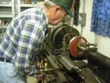
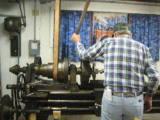
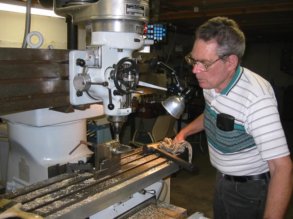
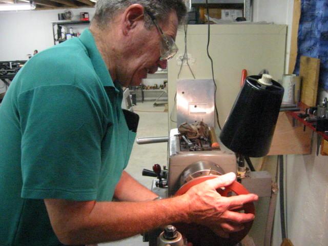
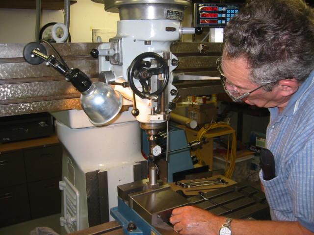
Bill at the controls.
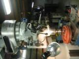
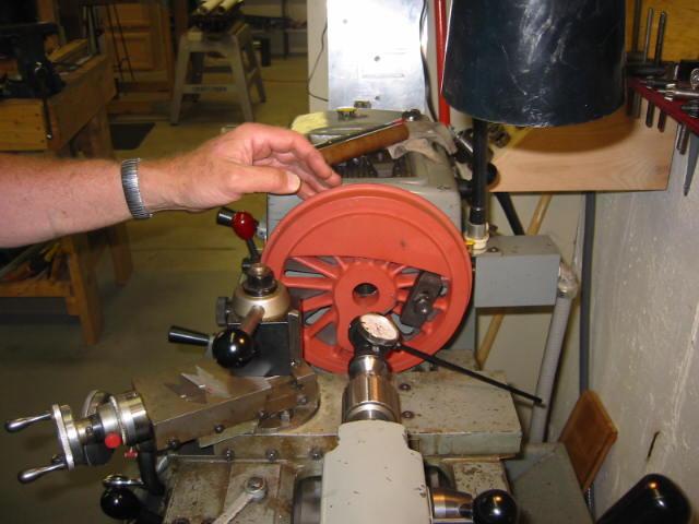
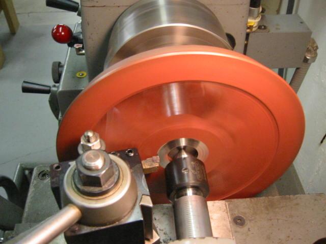
Machining the wheel tread to match the other wheels.
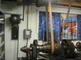
The very noisy chain drive on the overhead pulleys.
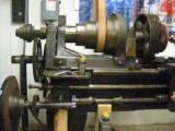
The geartrain in motion on the big Rahn-Larmon lathe.
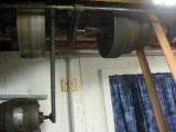
The very noisy overhead chain drive for the big lathe.
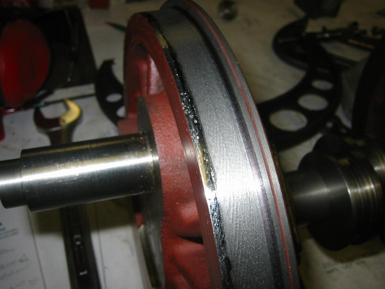
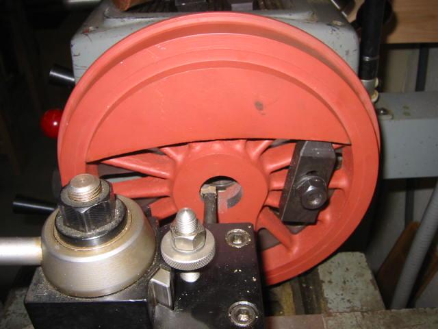
The turned flanges - note how the left side needed very little material removed, while the oversize flange on the right had a lot to make it the same size as…
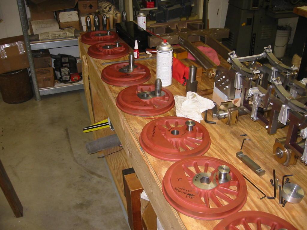
Wheels in a corral
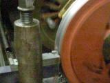
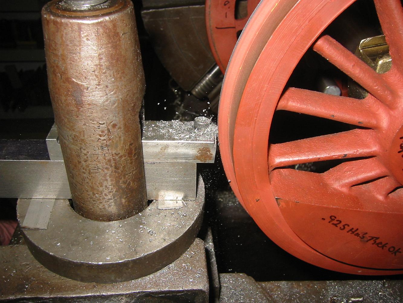
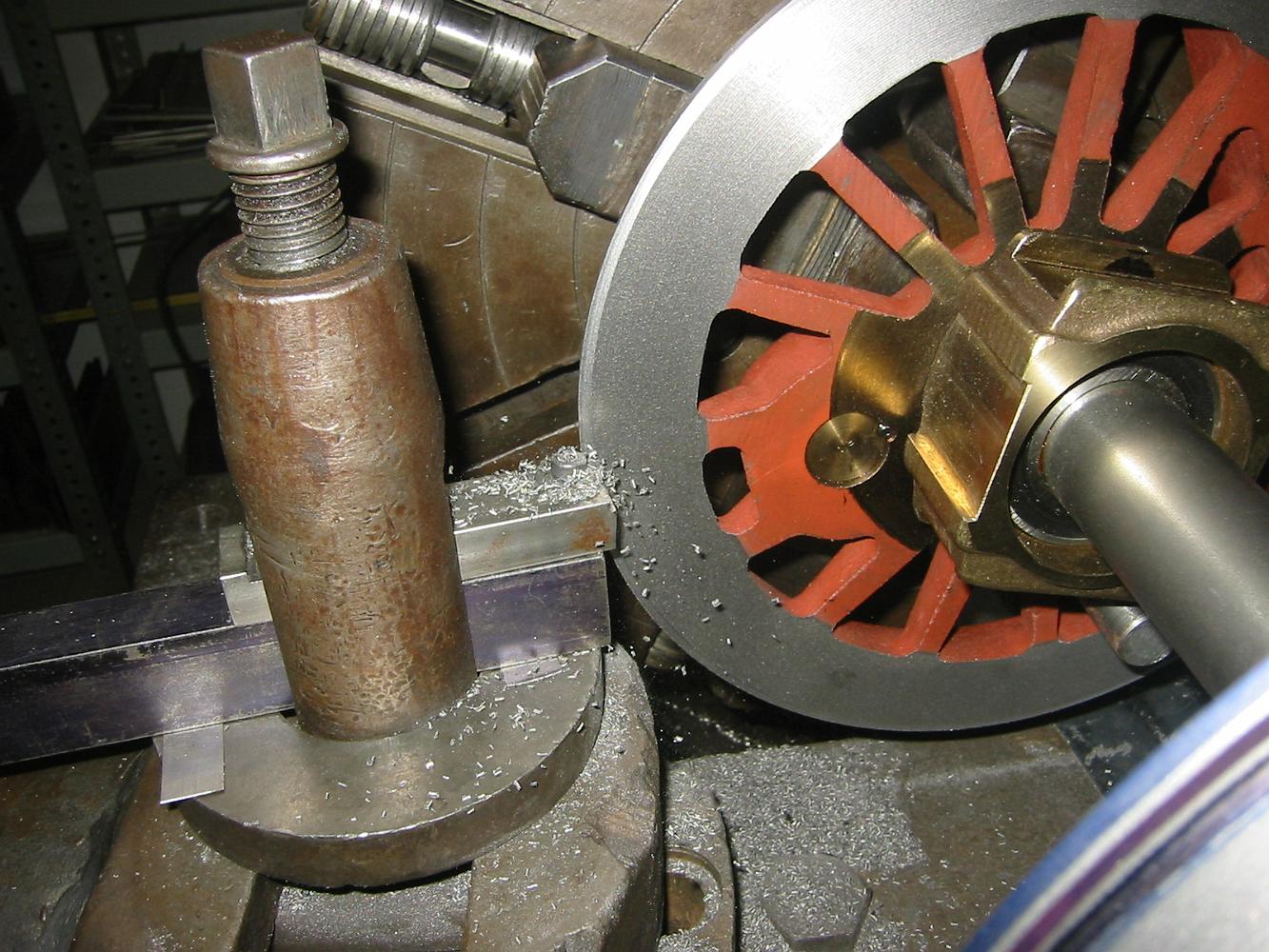
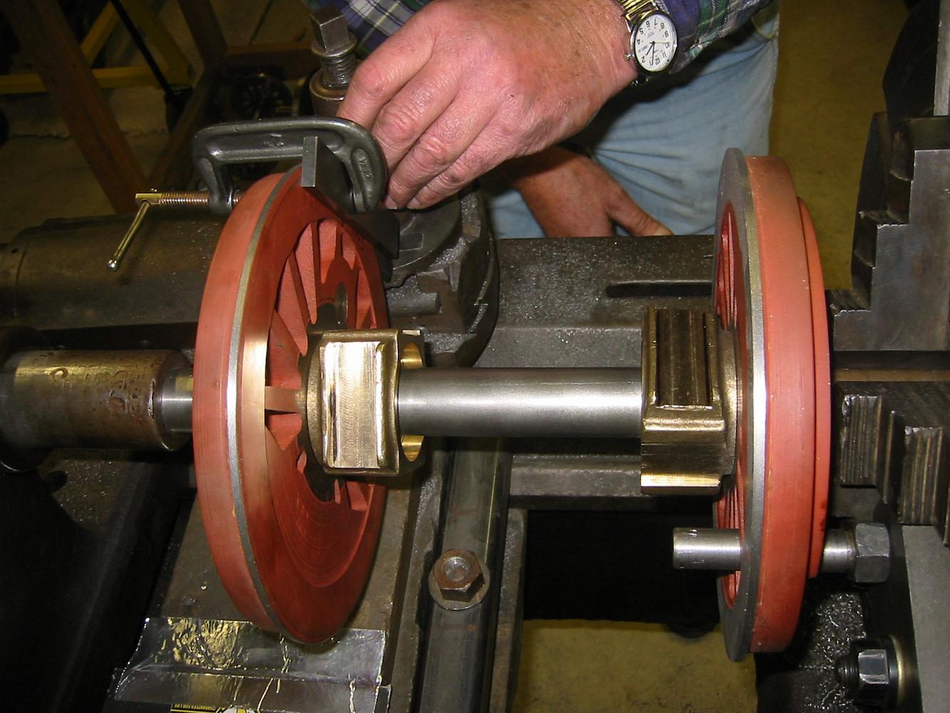
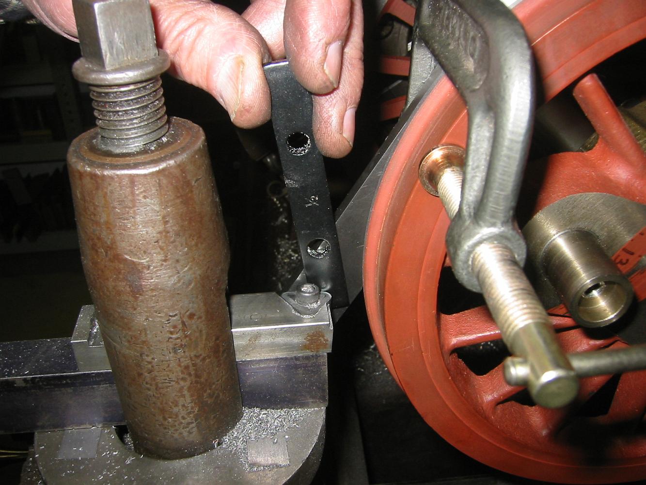
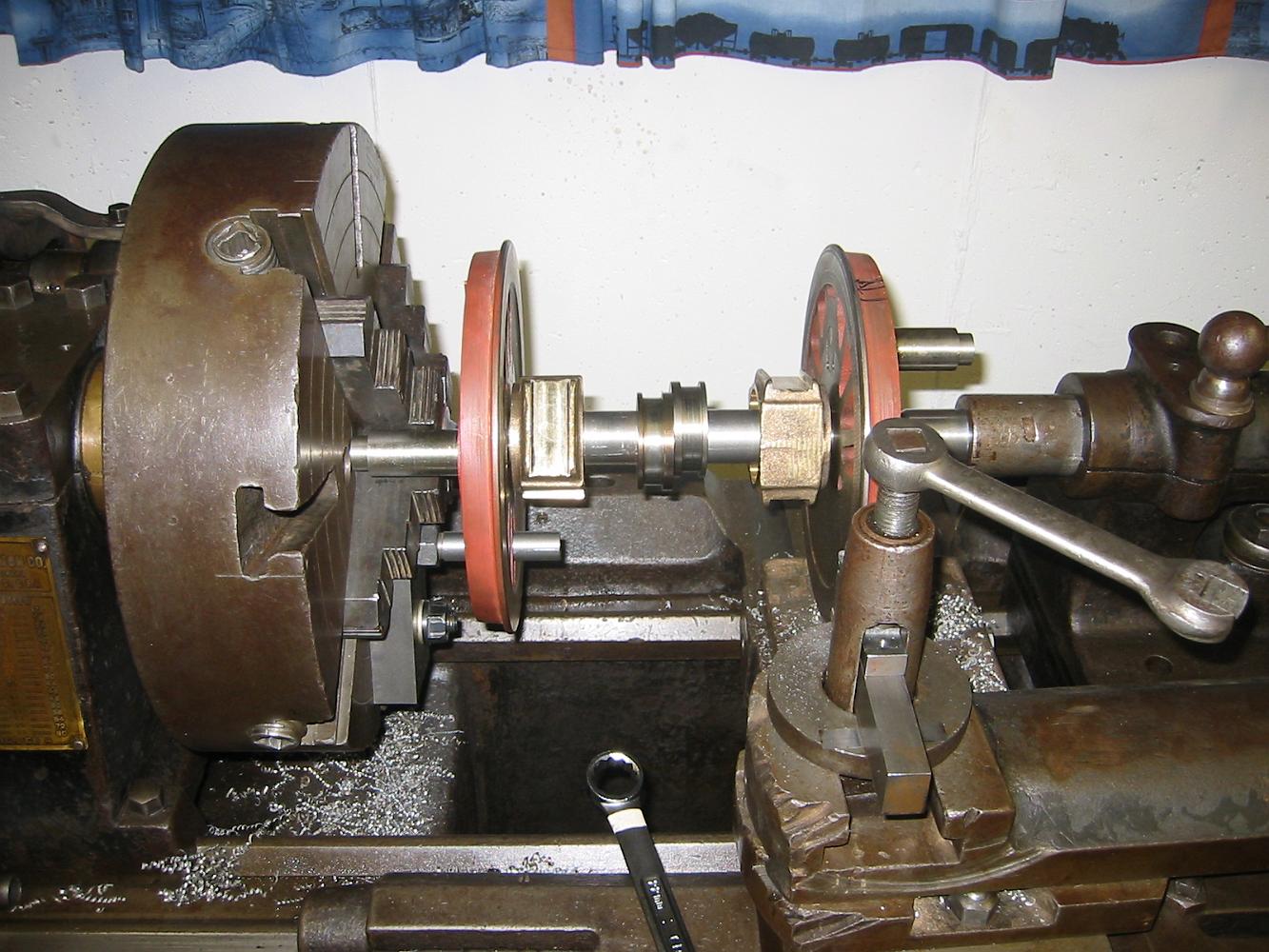
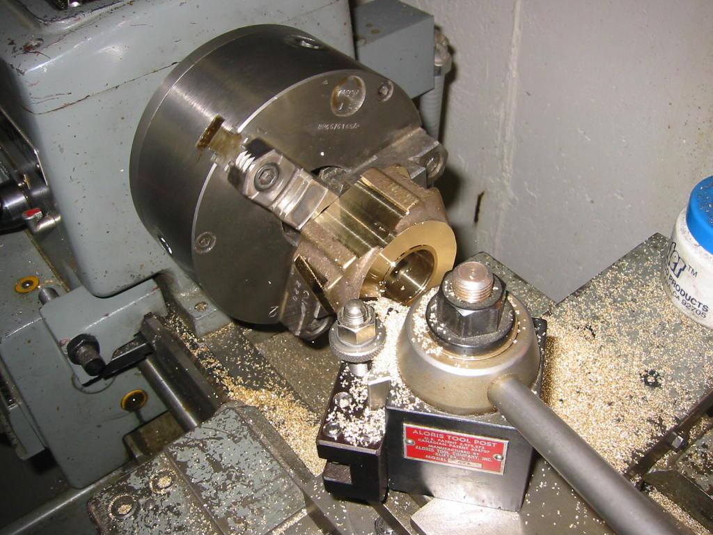
1-Dec-07 Making a drive dog for the wheels. The dog is bolted to the lathe chuck. A threaded bolt will go in the hole on the right, through the spokes in the…
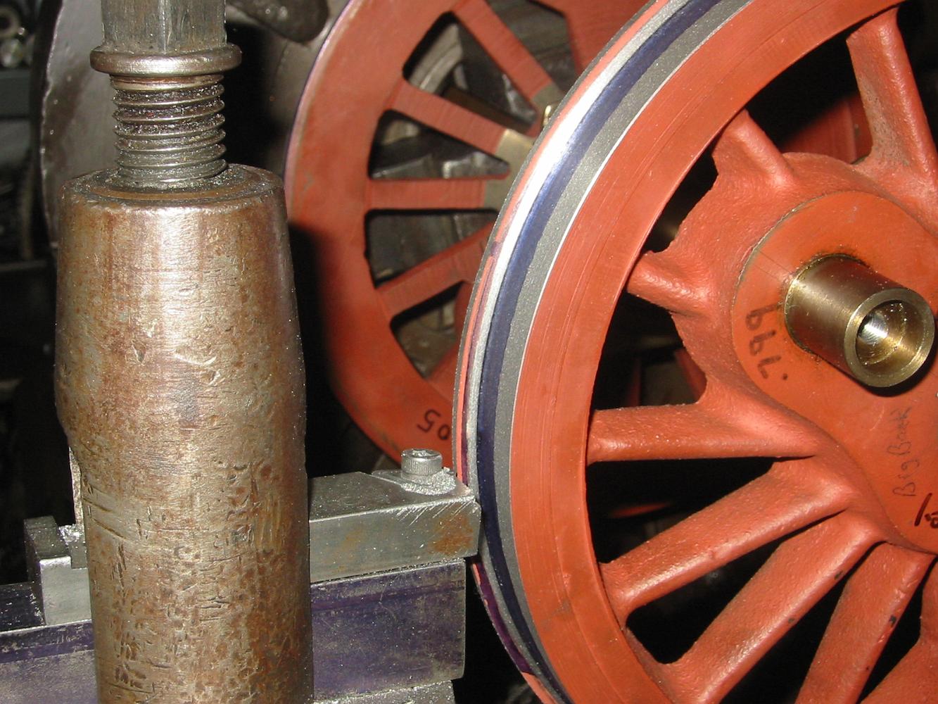
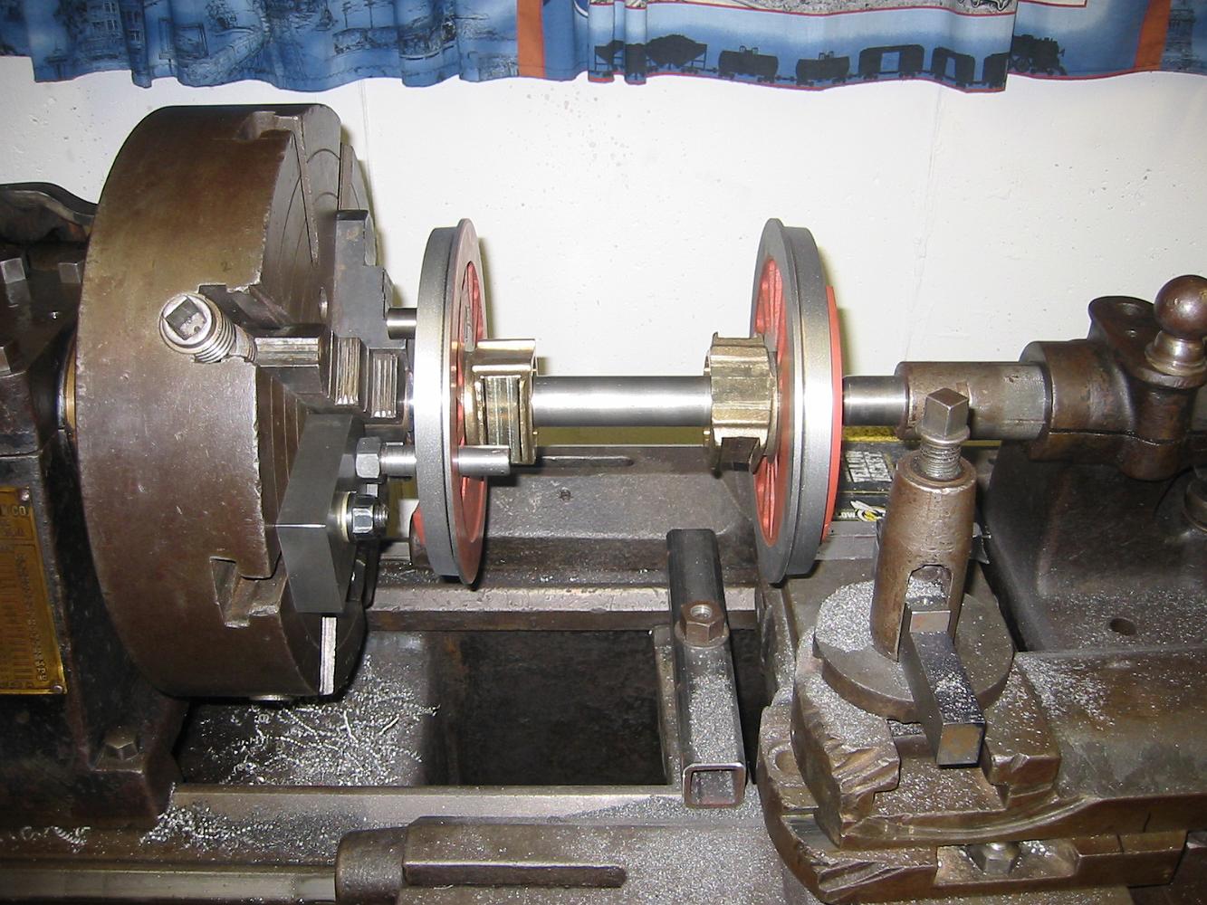
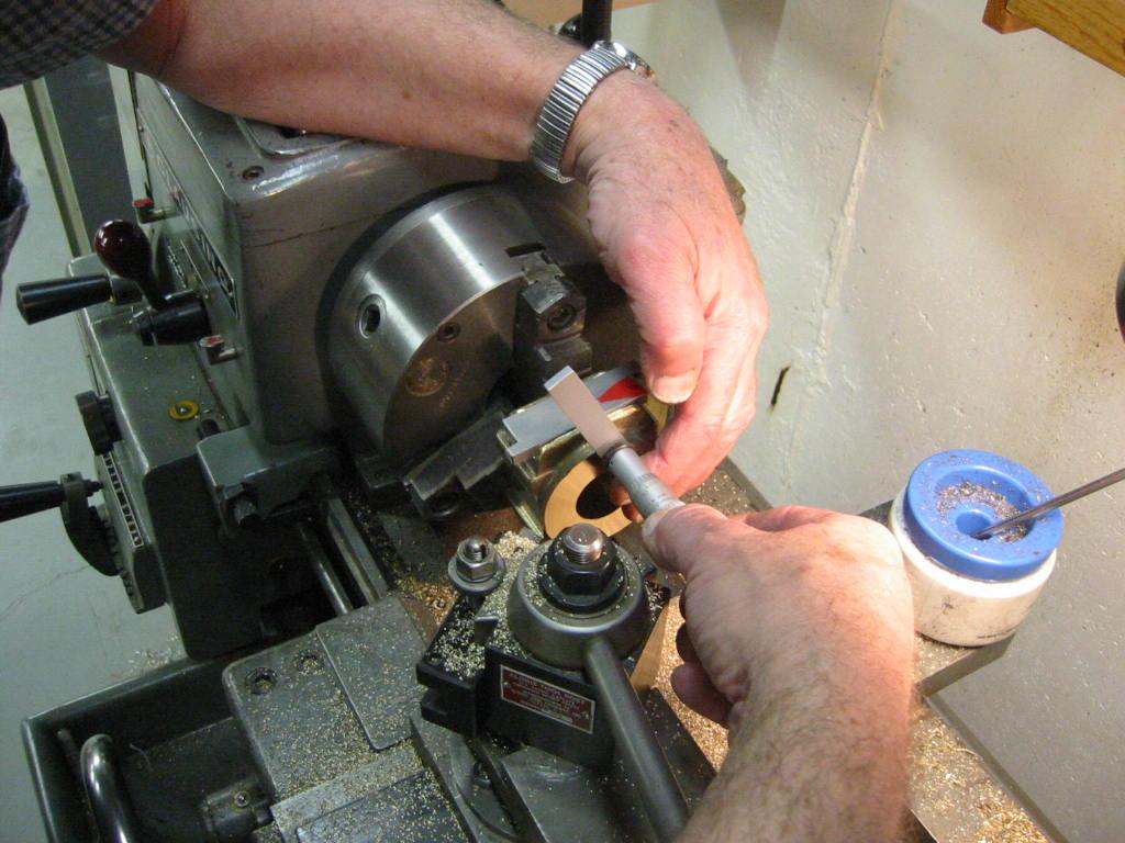
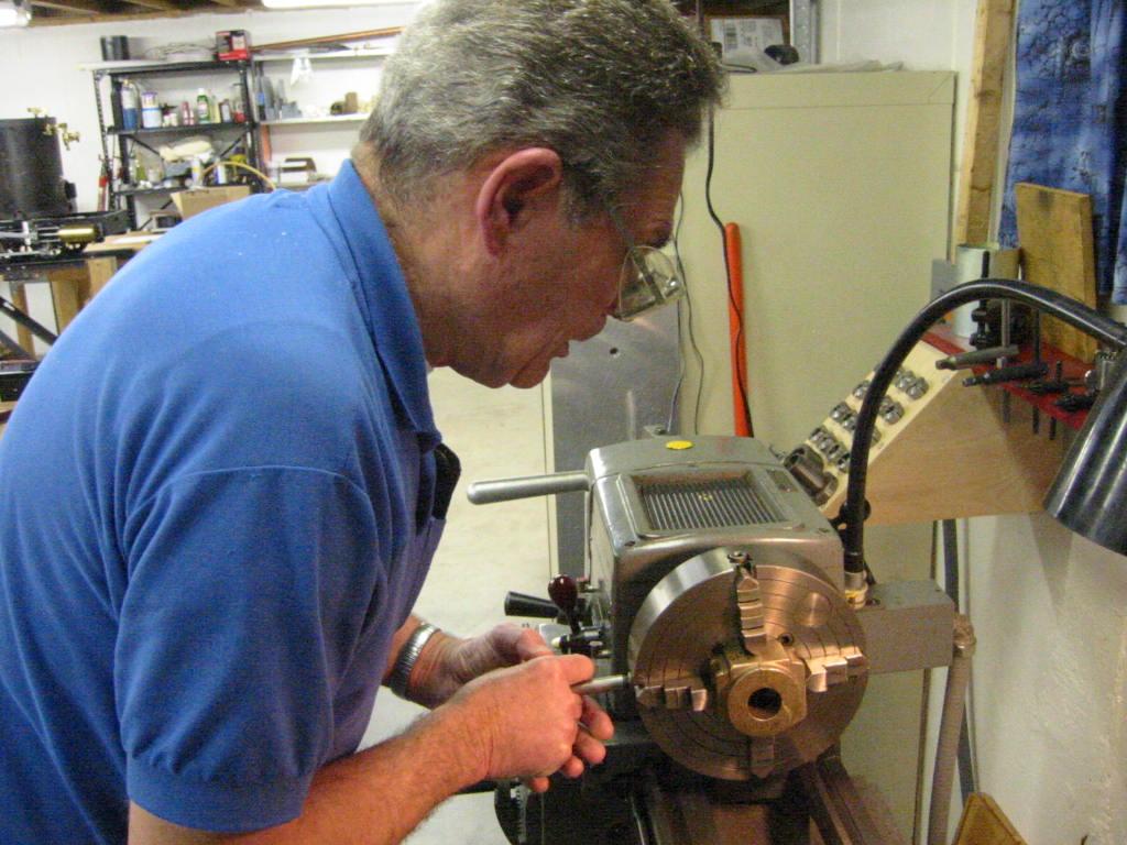
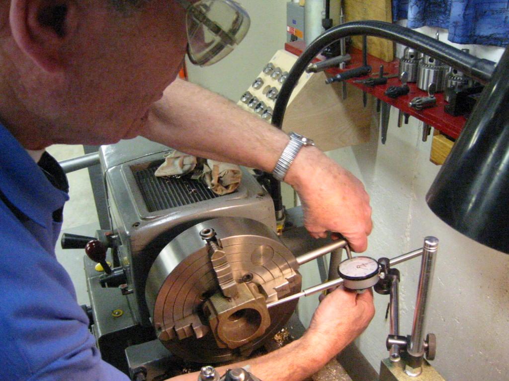
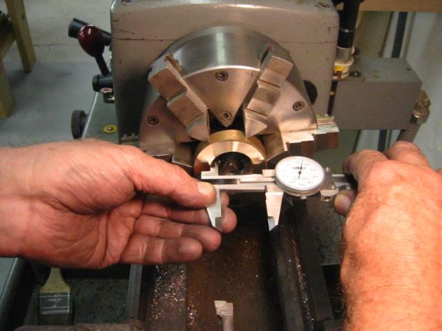
5-Dec-07 Measuring the Flange diameter with a 8-9" outside micrometer. The wheels as received were bigger on the left than the right by almost a quarter of an…
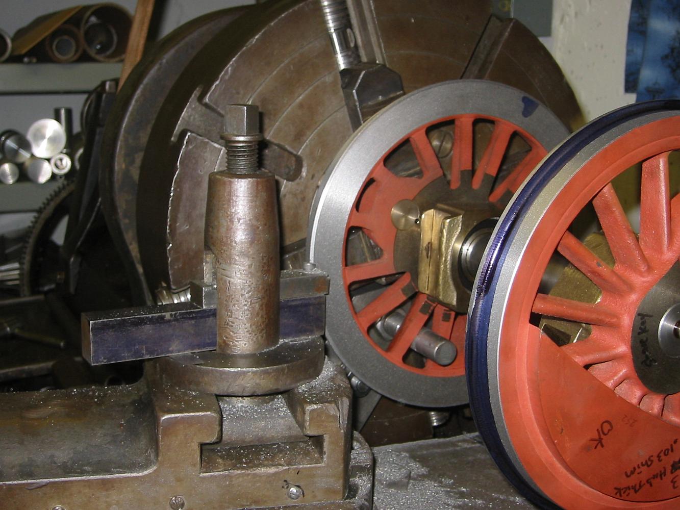
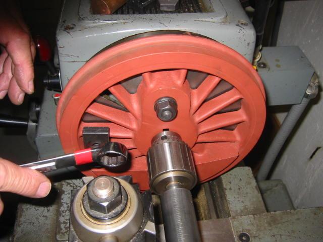
Turning the flanges to the same diameter in the old Rahn-Larmon lathe - note the 'lantern-post' rocker style tool holder.
8-Dec-07 We're almost done! Having turned the 3 degree taper on the tread (the main part of the wheel), we finish the wheel by putting a 10 degree taper on the…
The bluing on wheel allows us to see where the 10 degree taper is cutting, so we we don't cut too deep and gouge the tread.
Cutting the inside taper on the flange. We are almost done with this wheel - notice how the bluing has been removed up to the inside radius on the tread.
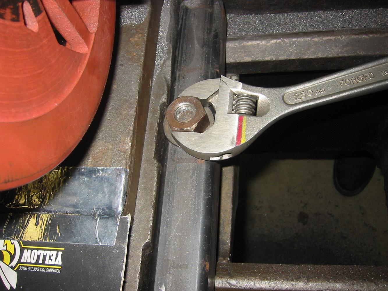
Tightening the shop made carriage stop.
Setting the cutter stop to insure all the flanges are the same width.
Setting the cutter stop to insure all the flanges are the same width.
8-Dec-07 A classic setup in the lathe - The part held between centers insuring maximum concentricity.
A surprise under the red primer paint is uncovered - nickel fill welding. Welding on cast iron, which the wheels are made of, is not generally recommended.
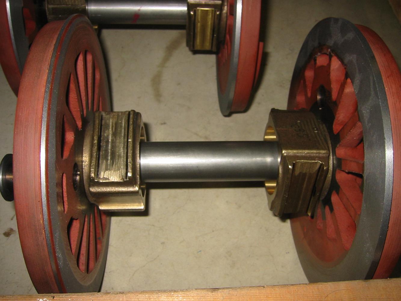
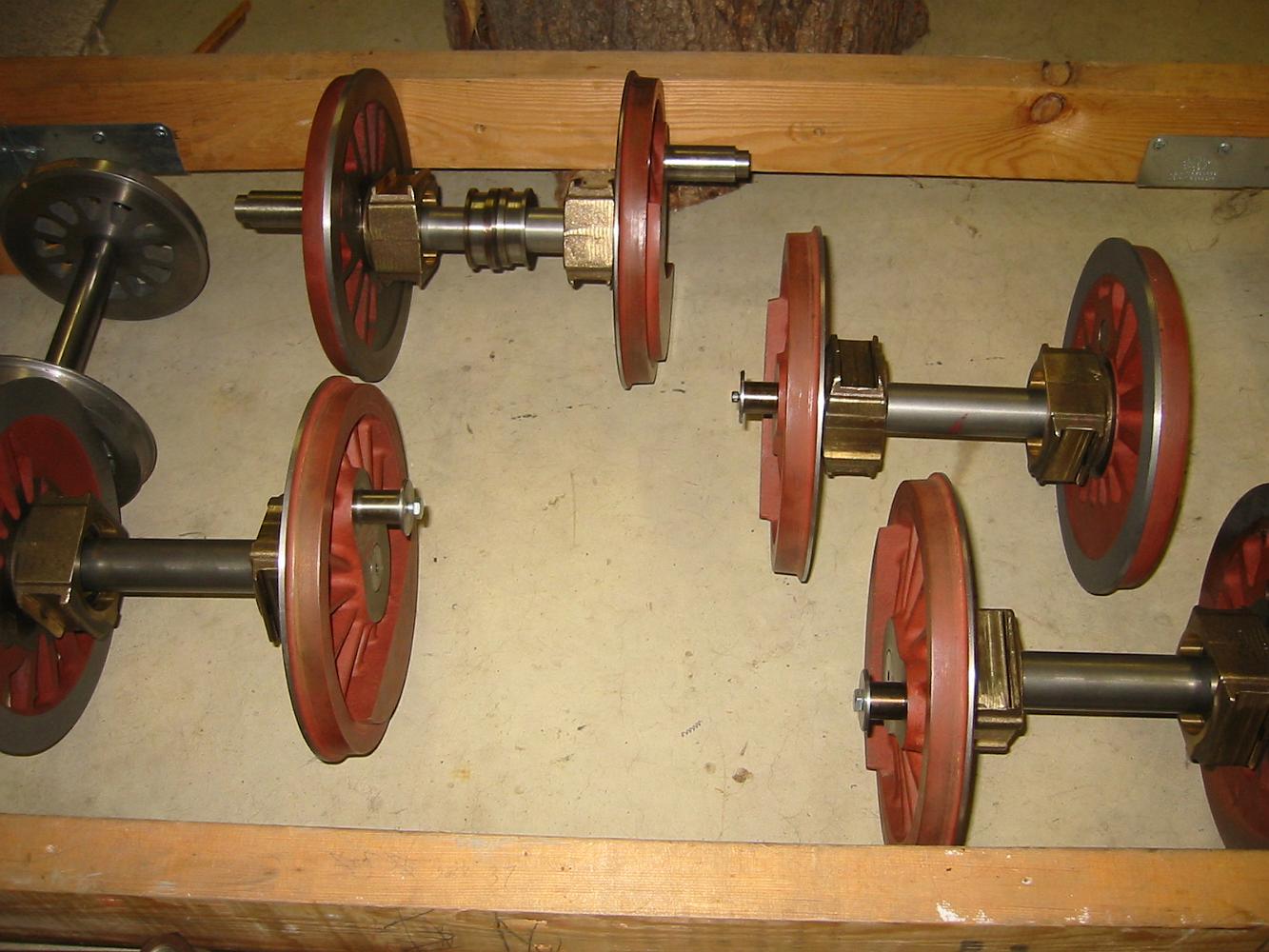
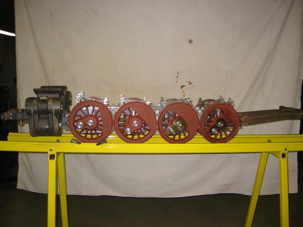
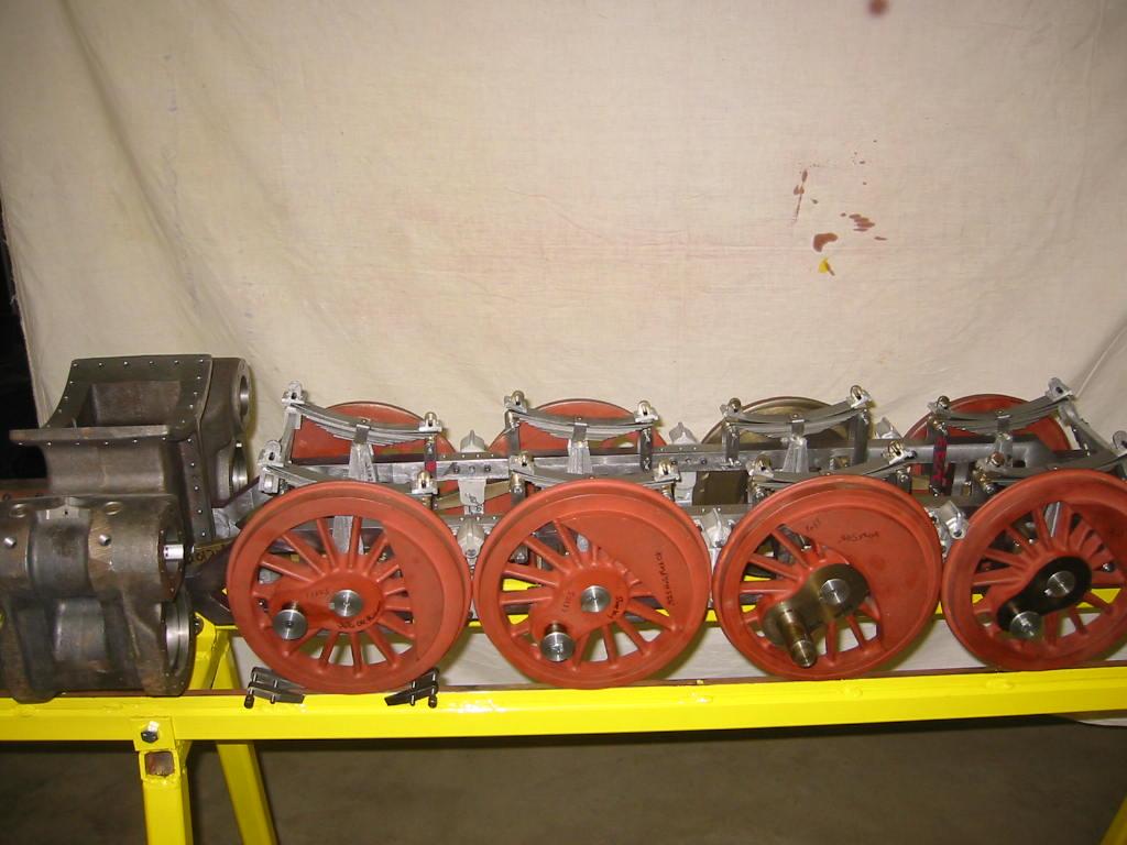
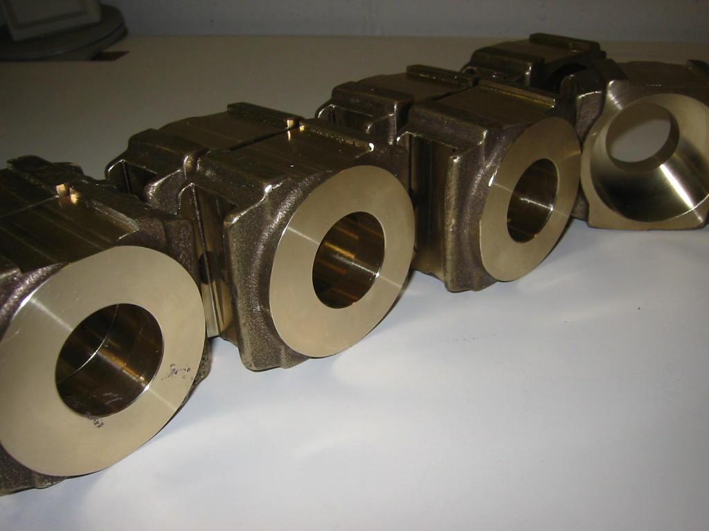
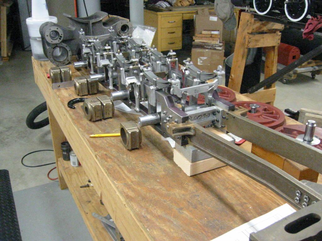
1-Apr-06. The wheels are coming together. Here they are all lined up with the crank pins solidly anchored. Now it is time to press the wheels to the axles!
20-Apr-06 Wa-hoo! Check out the locomotive now! The wheels have been pressed together and put under the frame. The suspension comes to life and the size of the…
1-Mar-06 Using a depth mike to measure the thickness of the thrust face. The print dimensions are from the centerline of the frame , not the back of the box.
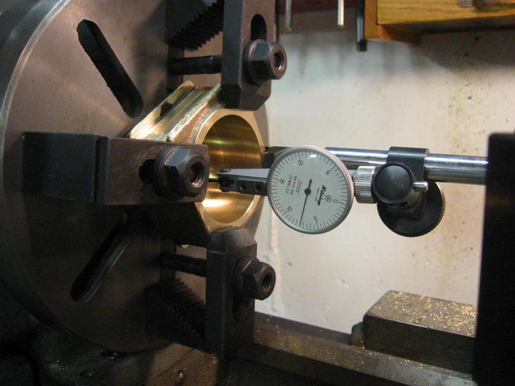
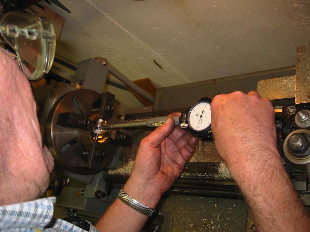
1-Mar-06 Finish bore the axle boxes to be 0.002" bigger than the ball bearings which slide inside it. First step: make it run true to the current bore. We could…
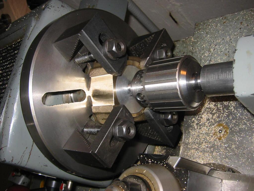
1-Mar-06 Here's how we rough centered the axle box before using the indicator for fine adjusting. We put the aluminum plug, which we used during previous steps,…
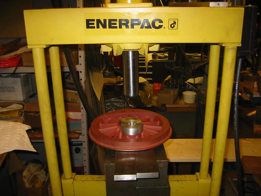
22-Mar-06 Time to press the crank pins into the wheels. We went to my friend Joel's shop because he has a 10 ton hydraulic press. Since our crank pin holes were…
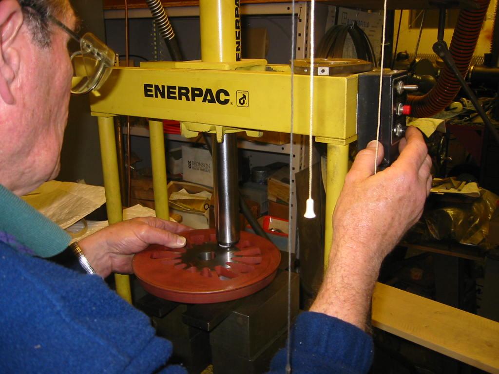
22-Mar-06 Pressing the crank pins into the wheels. For the main and intermediate wheels, we press them in from the back. The electric hydraulic pump made quick…
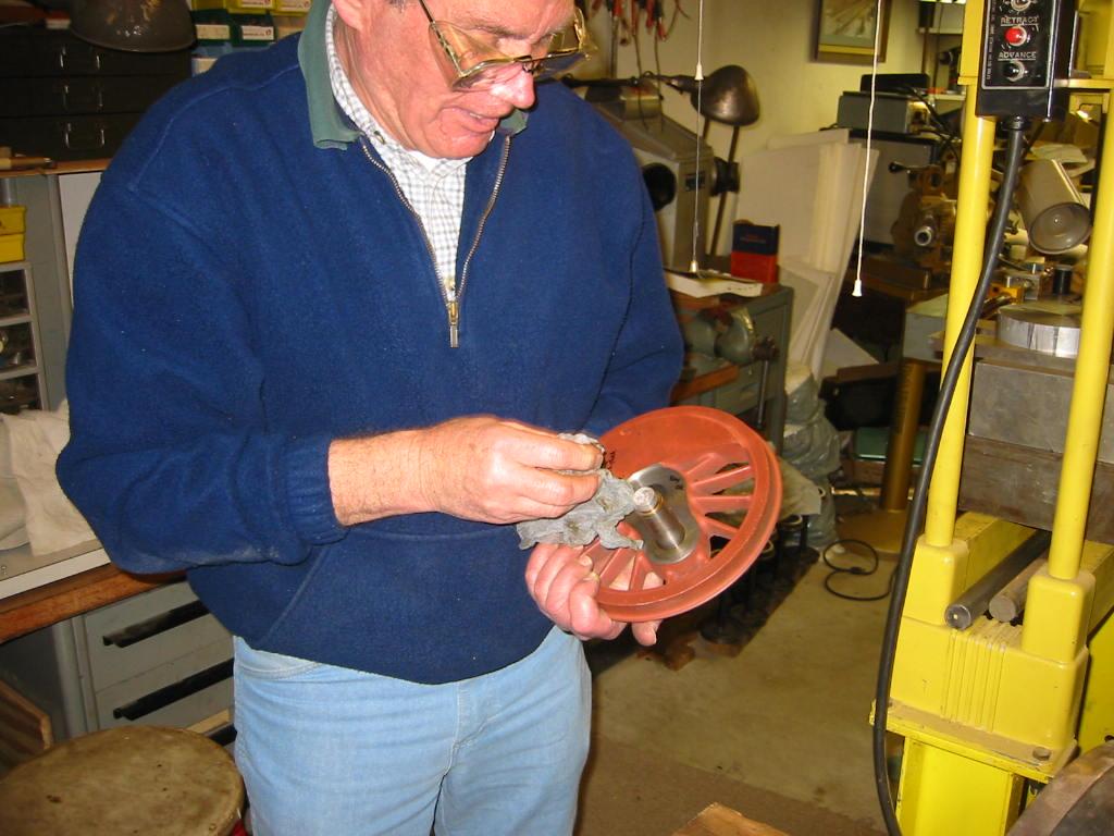
22-Mar-06 The main driver with the crank pin pressed in. Bill wipes away the excess oil (we did not want the steel pin to gall on the cast iron, possibly…
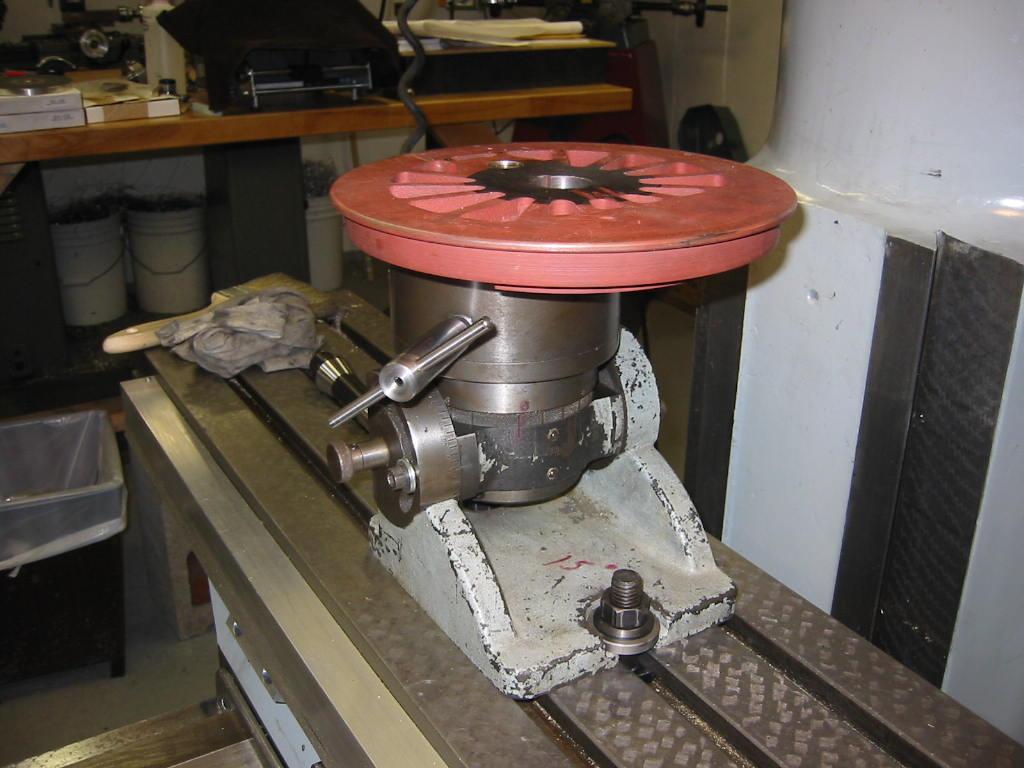
29-Mar-06 Using a rotary chuck given to me by Jim H. back in my parents neighborhood, we gently chuck up the wheel by the crank pin to drill, tap and setscrew…
29-Mar-06 Using a wiggler to find the exact point between the pin and wheel. We will drill, tap and Loctite a shoulder screw that is half in the pin and half in…
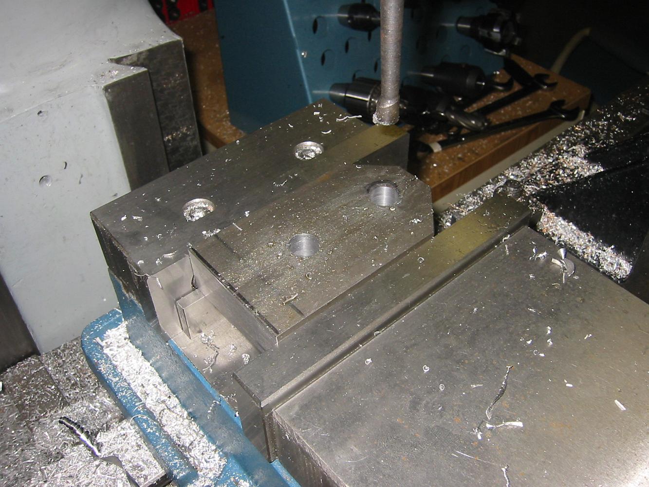
22-Feb-06 We would machine the top of one axle box, then loosen the C clamp and rotate the box around the aluminum plug, use the parallels to square things up…
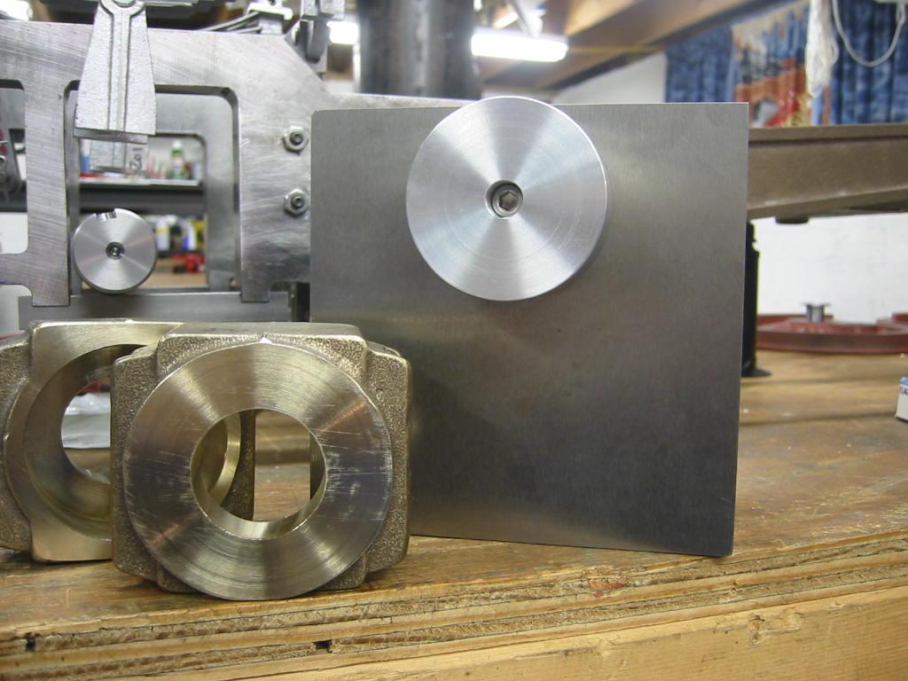
11-Jan-06 We make another fixture for machining the outside of the axle boxes. Shown here is the rough bored box and on the fixture.
11-Jan-06 We turn a chunk of aluminum down to be a sliding fit to the inside of the rough turned axle boxes. The gray iron angle plate is drilled and tapped,…
18-Jan-06 Here's the setup for machining the axle box 'ears' or frame guides: Angle plate bolted to the table, axle box held to the plate with a C clamp,…
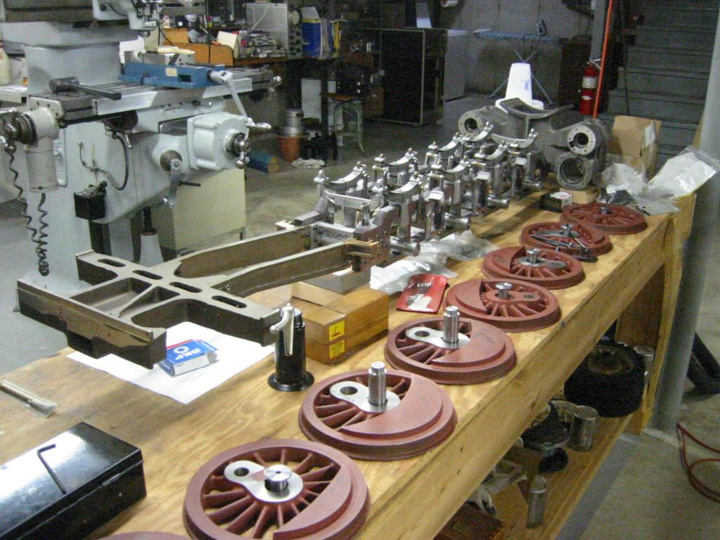
14-Dec-05 With so many parts completed I just had to line things up so see the progress. Next we need to complete the axle boxes and assemble the wheels.
14-Dec-05 Time to start working on the axle boxes. First step: chuck it up in the four jaw and machine the reference surface, which is also the thrust surface…
14-Dec-05 We do what we can with the limited tools on hand, in that case we try to center the casting to rough bore the bearing recess. This is a bit…
14-Dec-05. Grab the boring bar, fiddle with the center height, rake angle and point to reduce the chatter for a good finish. This is not the final diameter, but…
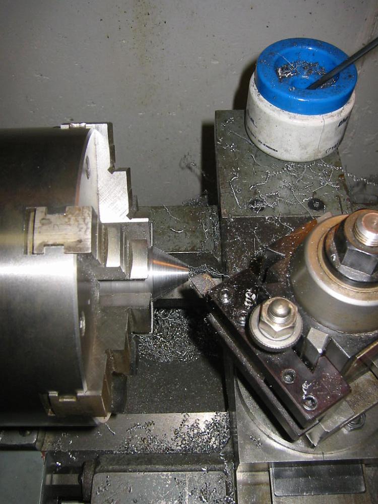
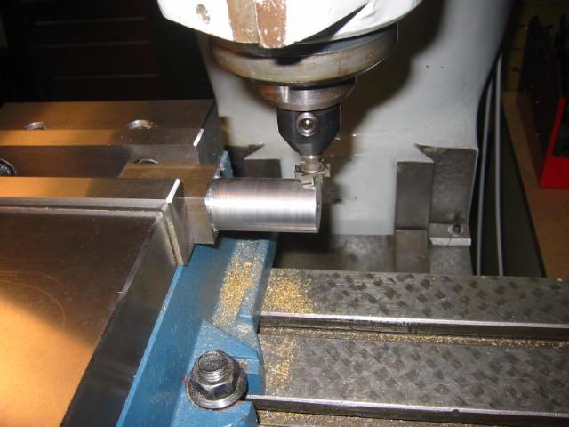
23-Nov-05 Making an accurate dead center. We will leave this in the chuck, undisturbed to turn the axles between centers.
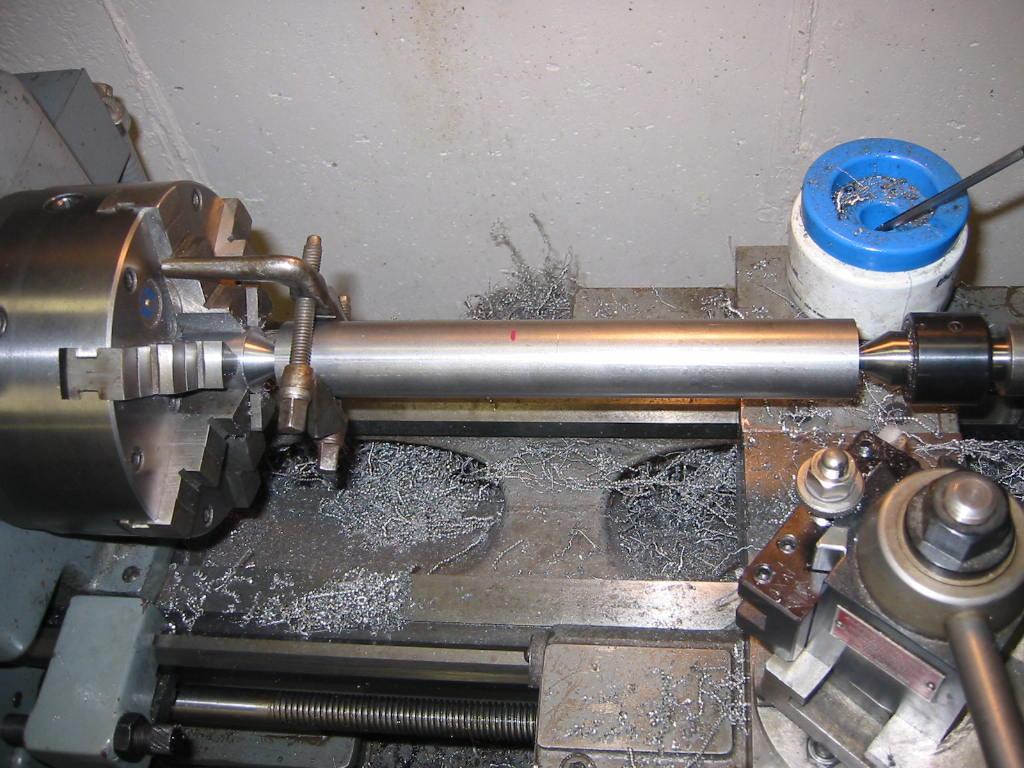
25-Nov-05 Turning the axle shafts. This involved turning to the correct diameter and length for one operation, then turning the axle around between centers…
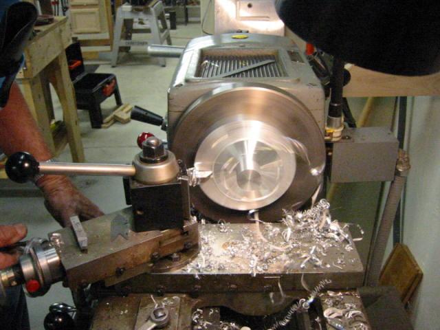
3-Aug-05 With the axle and crankpin holes completed, we now have to face the front of the wheels. Which calls for another fixture to hold the wheels. A large…
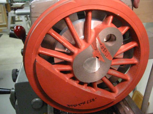
10-Aug-05 How the mandrel was mounted on the faceplate, including the offset. If we had left the stub shaft on center we would machine the counter-weights off…
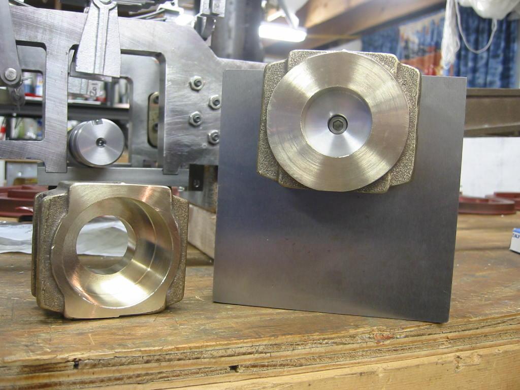
10-Aug-05 The front of the wheel hub after machining. Not all the previous machining marks were removed.
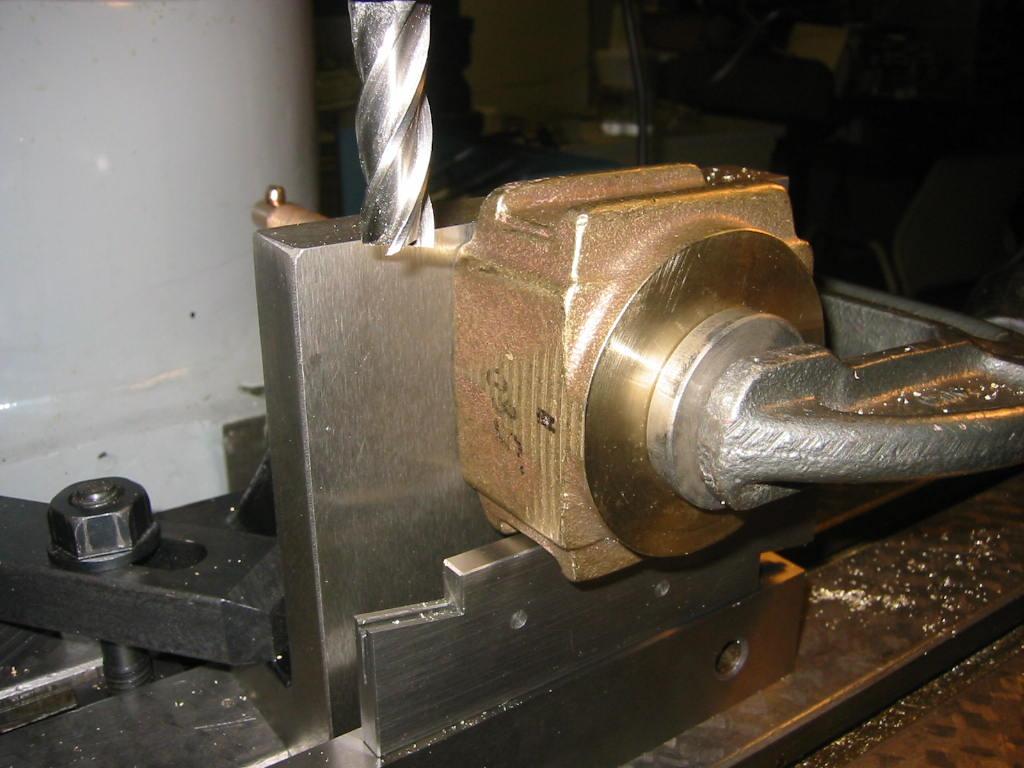
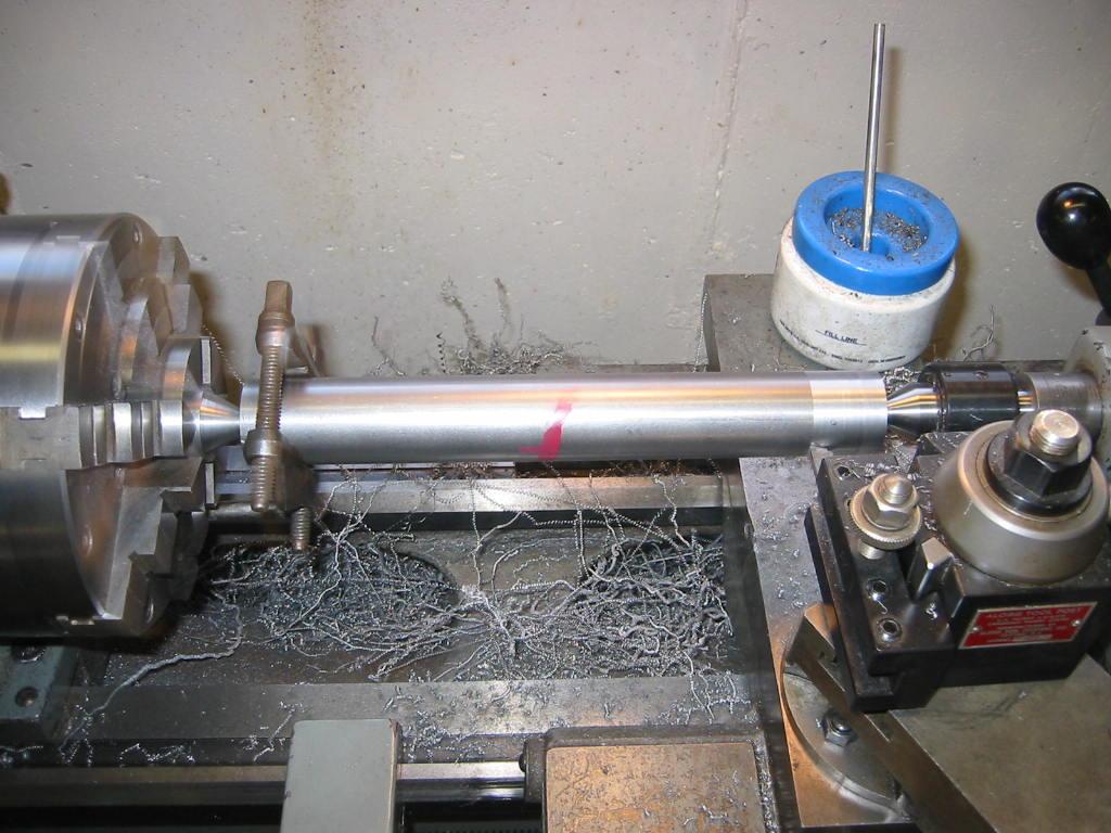
25-Aug-05 Machining the crankpins. We had to do some figuring since after machining the new crankpin holes that part of the pin held in the wheel did not match…
6-Jul-05 With the spring rigging done, it is time to work on the wheels. The quality of the wheels from the supplier was good, but, we were not satisfied with…
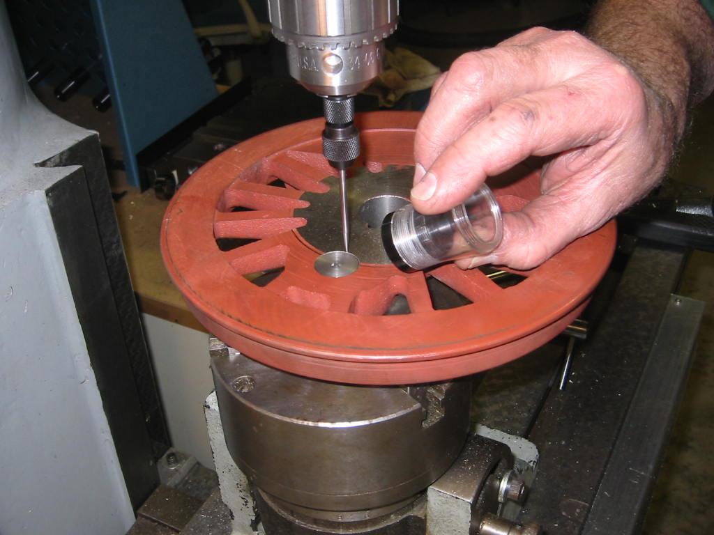
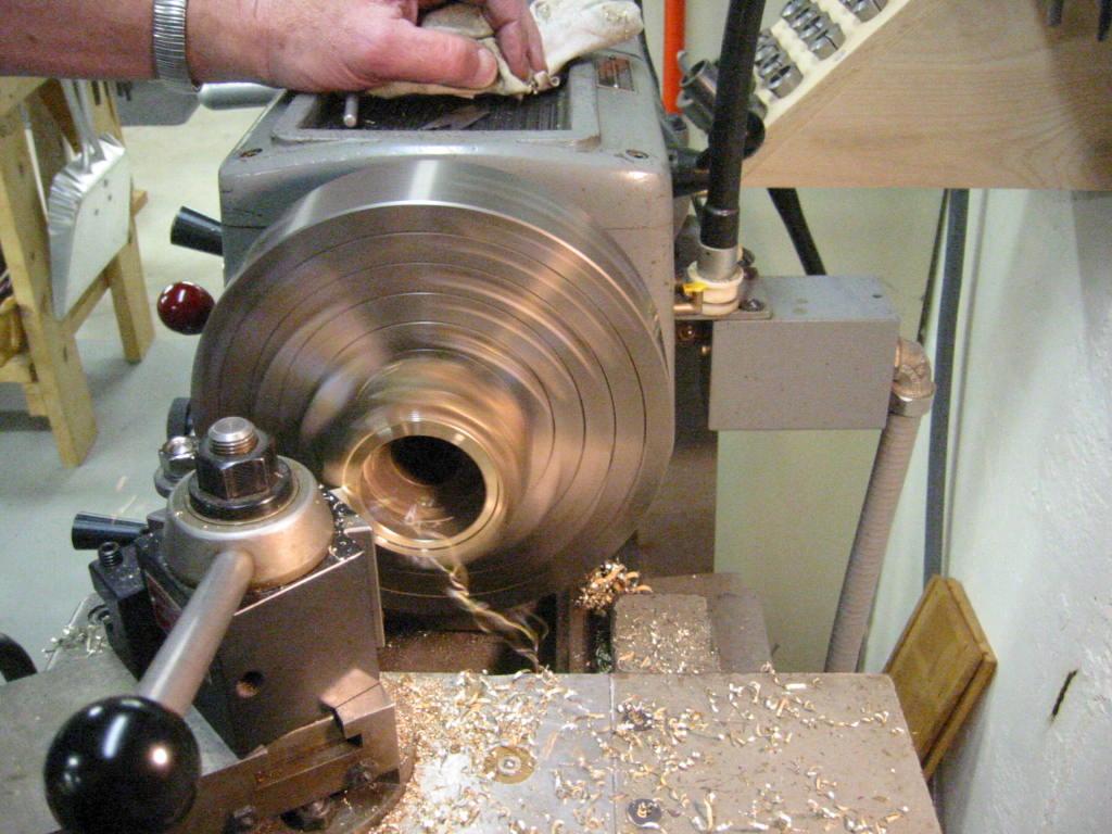
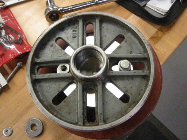
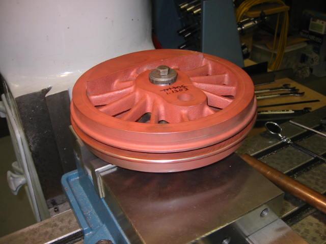
6-Jul-05 The first step is to bore the axle shaft hole. Mounting the wheel on the lathe faceplate, we approach the capacity of my little lathe. We used a…
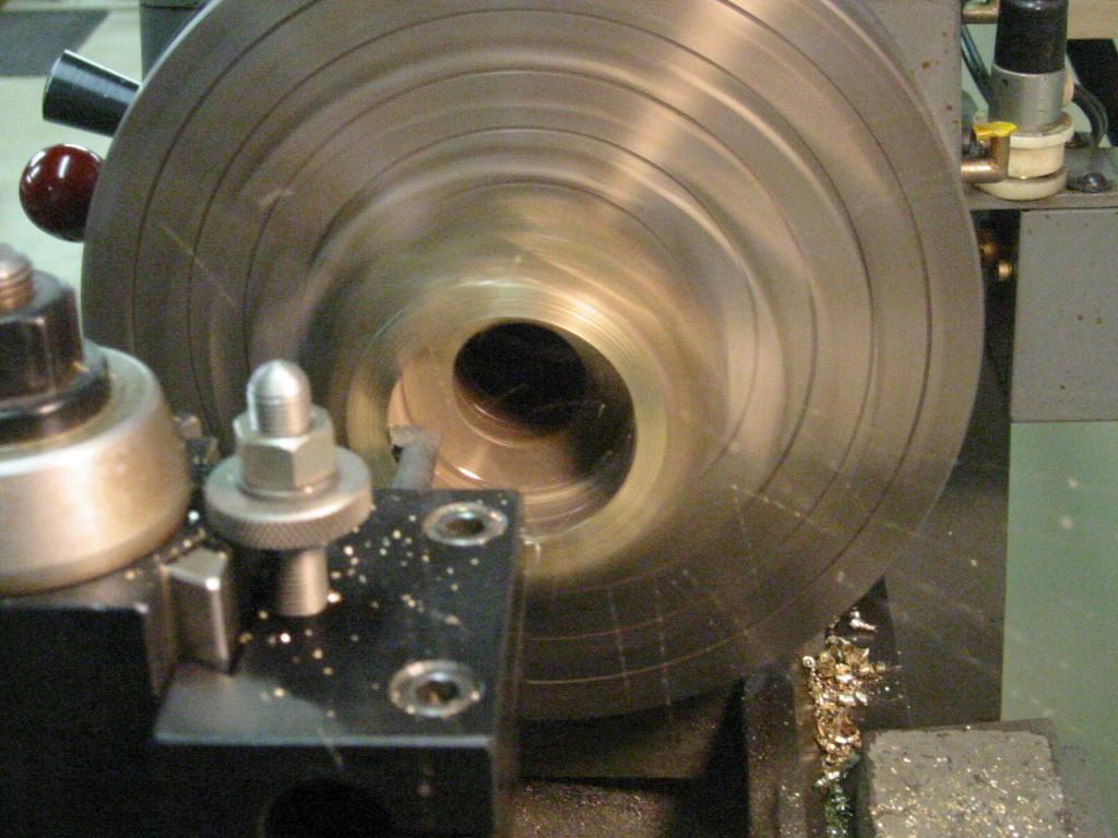
6-Jul-05 Running a slow speed in back gear, we run a truing cut through the hub. Since the keyway is already in the hub, this is an interrupted cut, but the…
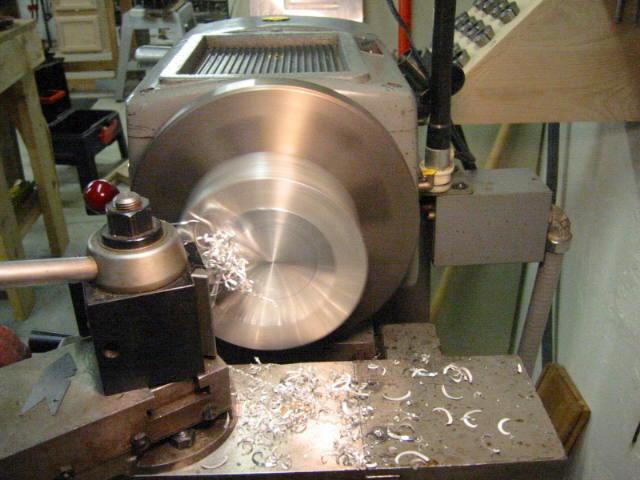
6-Jul-05 The massive counterweight of the main drivers caused the lathe to jump a little as it swung around, but nothing so serious that it actually moved.
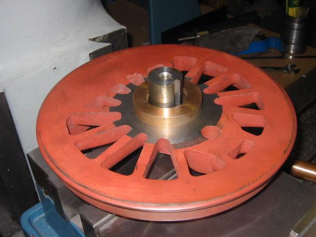
13-July-05 Once all the wheels were bored out, we made a close-fitting mandrel (or stub shaft) in the 4-jaw chuck to mount the wheel on. The friction fit drove…
13-Jul-05 Truing the back to the newly bored hub hole. You can see the end of the arbor in front of the live center.
13-Jul-05 Machining a brass spacer to put between the two wheels. We discovered the crankpin holes on each wheel did not line up correctly when placed on a…