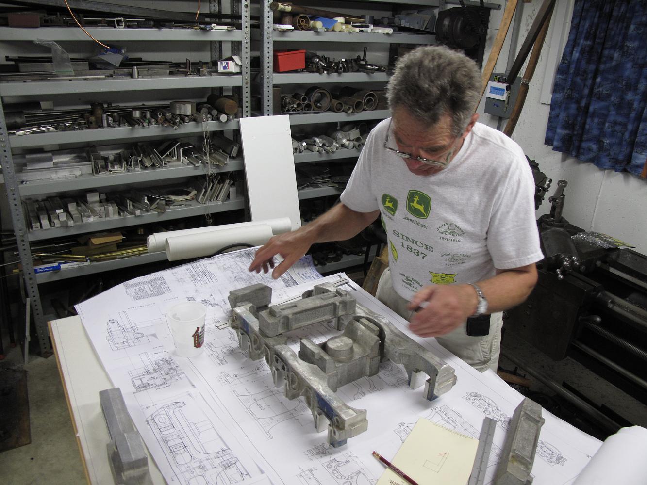
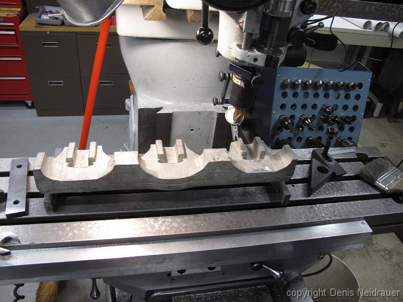
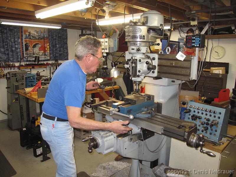
1-July-09 Bill and I strategize the machining approach with the three axle commonwealth castings I purchased. The castings did not come with an engineering…
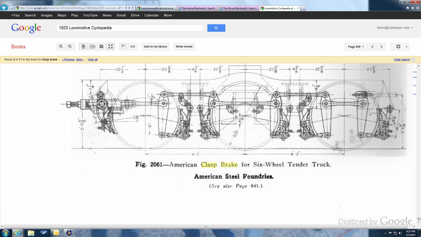
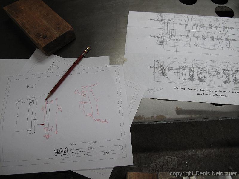
Need brakes for your six-wheel tender truck and don't have drawings? Let the 1925 Locomotive Cyclopedia be your guide.....
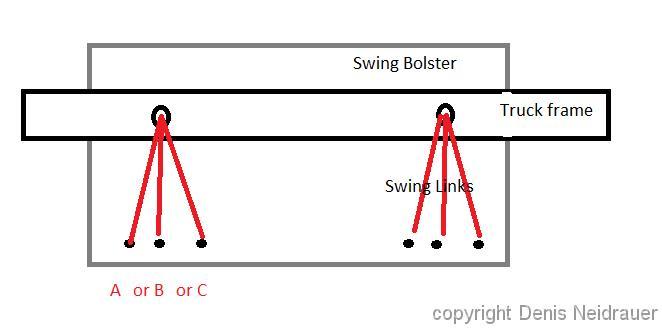
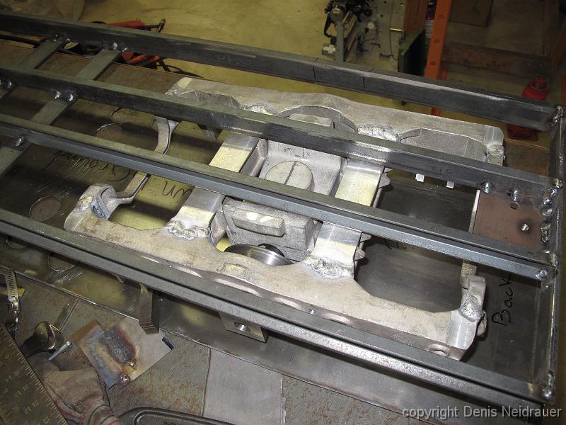
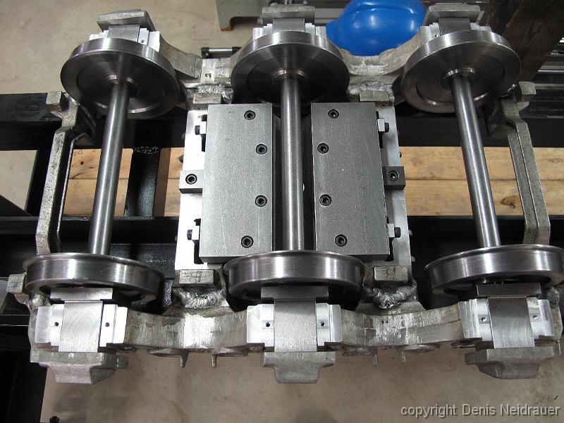
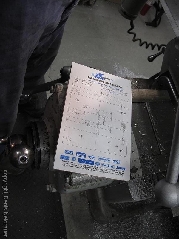
25-Nov-2013 A question sent out to the Live Steam Forum on The HomeMachinist BBS -- Which hole should we use to get the best bolster swing motion. We spent several hours puzzling over this.
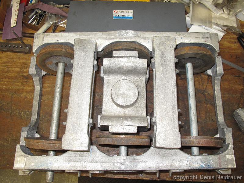
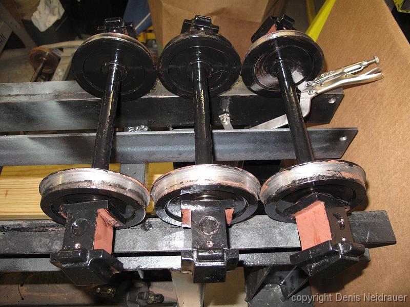
One possible way to assembly the parts. The wheels are a tight fit in the frame openings.
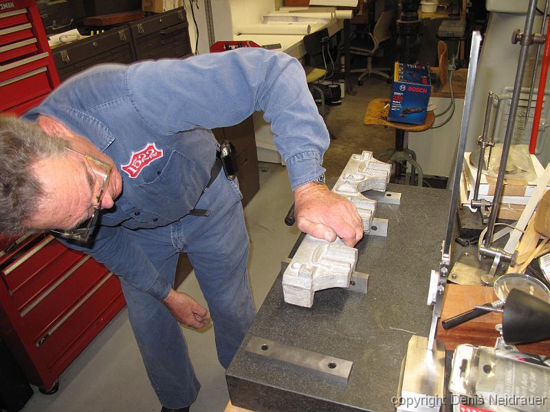
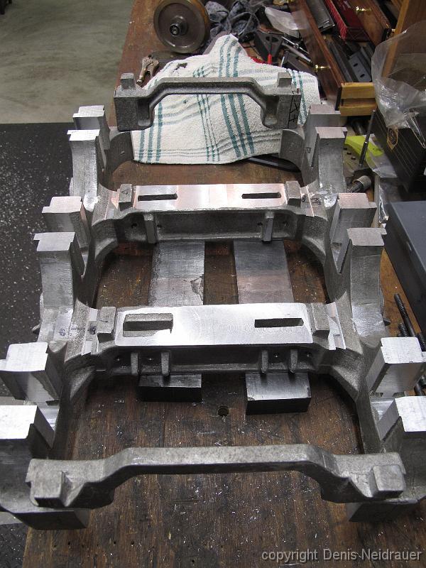
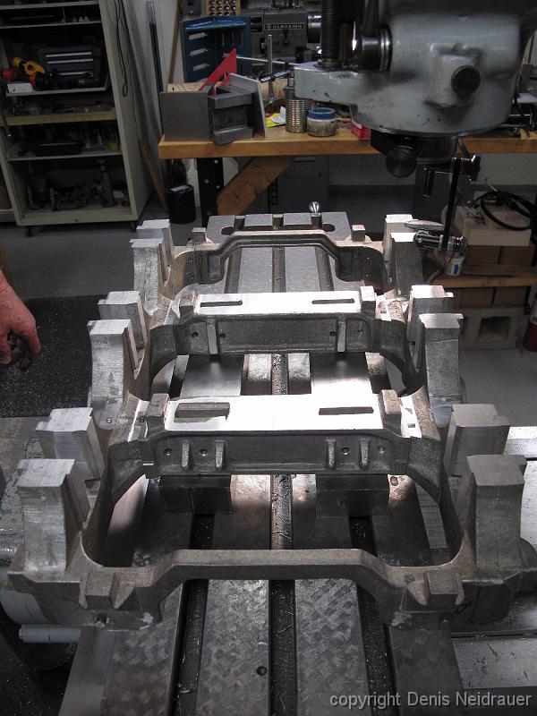
19-Nov-2012 Puzzling out how to hold the castings to machine them with the least number of setup changes. ?Do we elevate them on the table? ?Clamp them down…
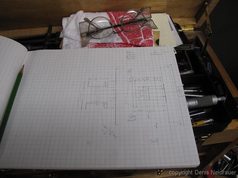
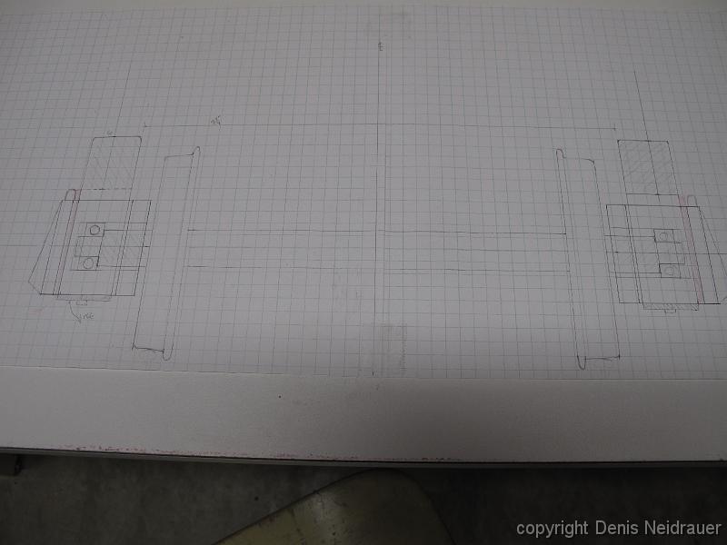
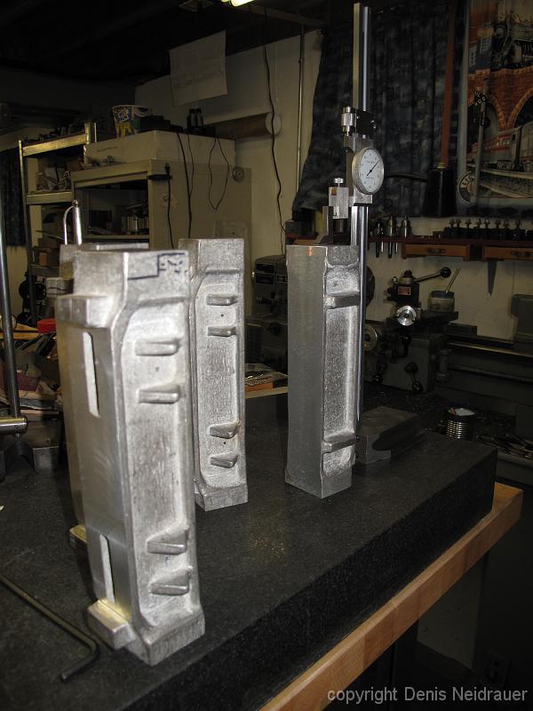
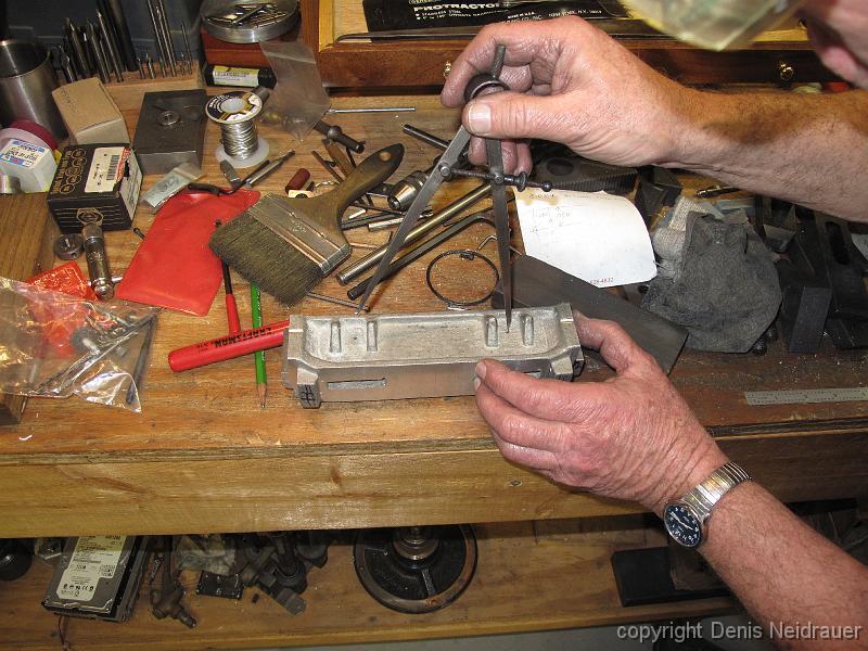
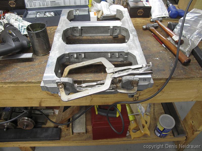
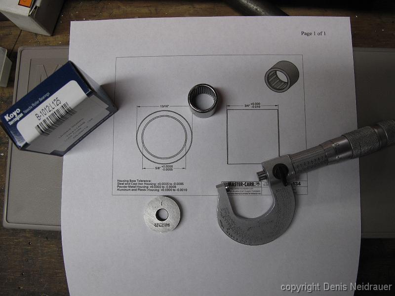
19-Nov-2012 Using gridded paper to see how the bearings will fit in the axle boxes. The castings came with some ball bearings, but the ID is 3/8" and the OD is…
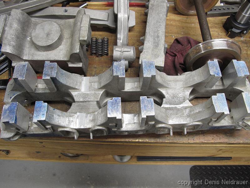
19-Nov-2012 Another machinist had started on one set of side frames. I always worry that we will run into trouble with someones previous work since we will be…
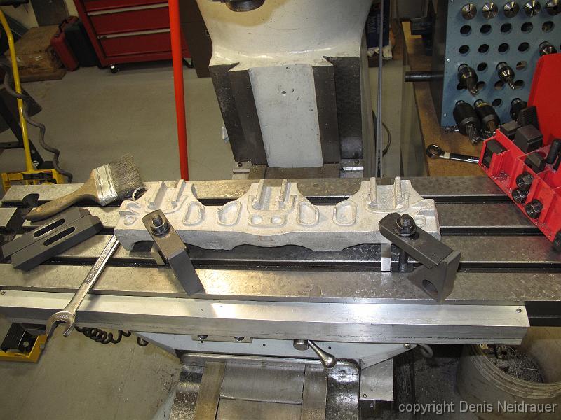
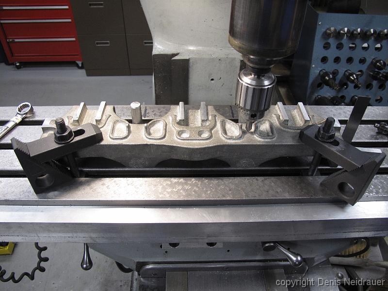
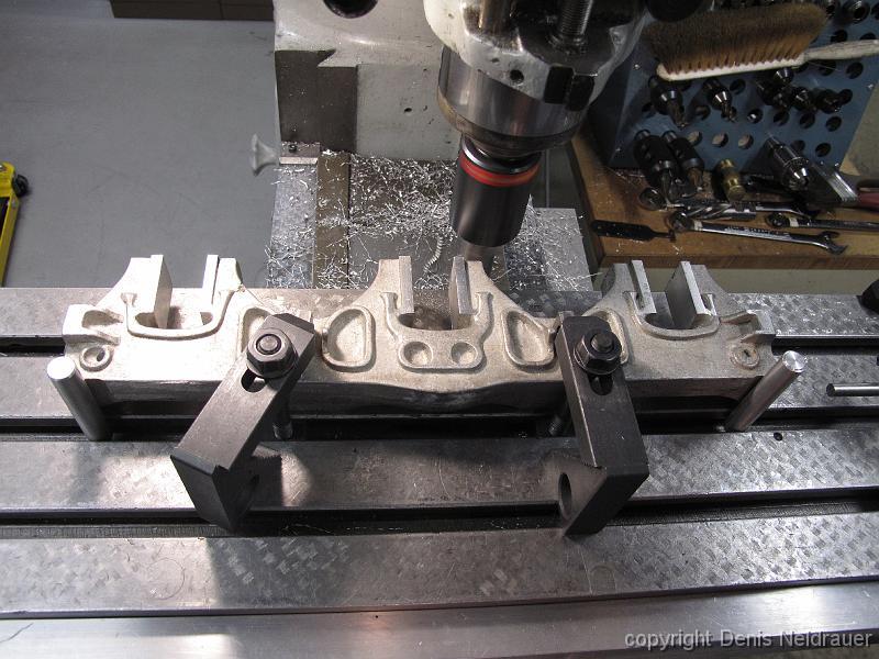
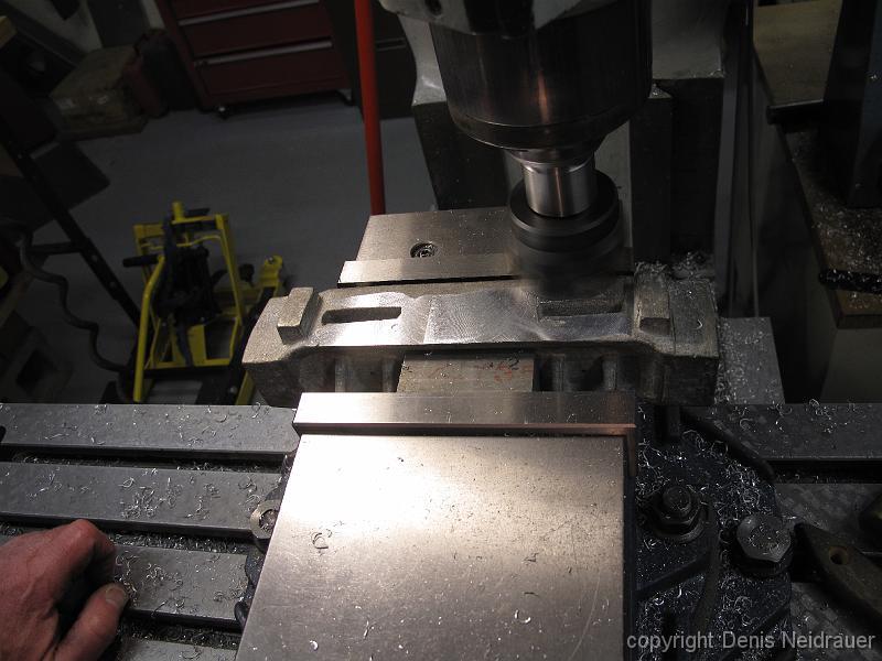
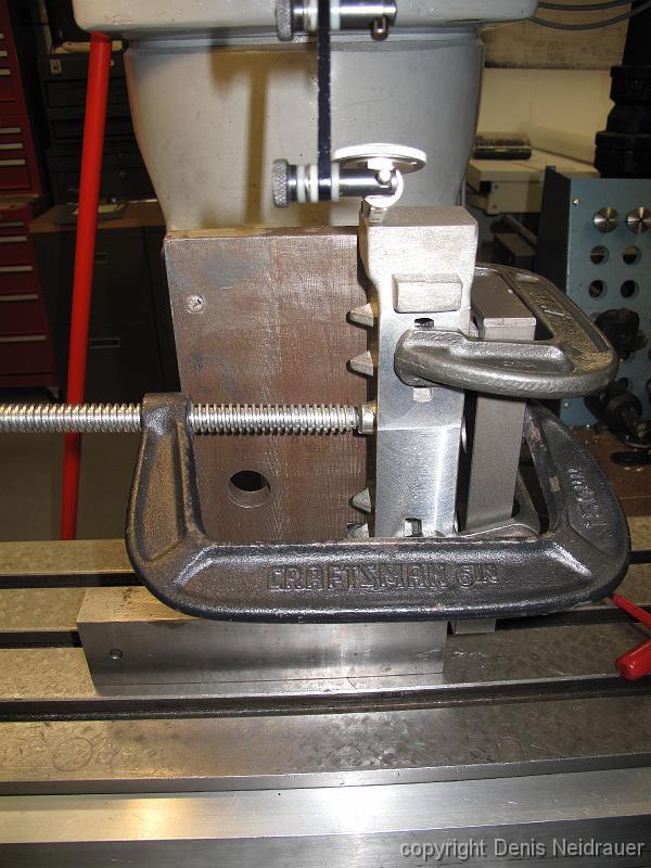
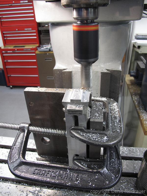
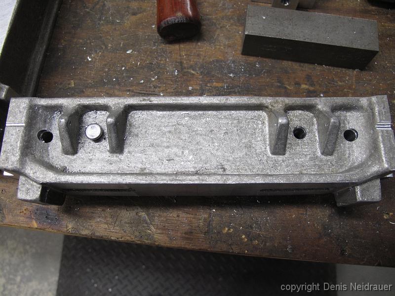
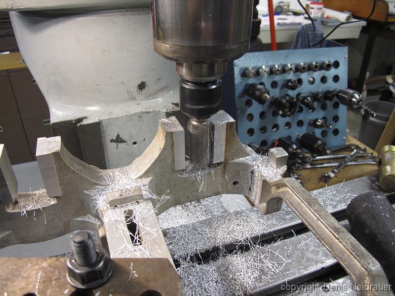
10-Dec-2012 First setup: clamp to the table for a skim cut on the pedestal openings.
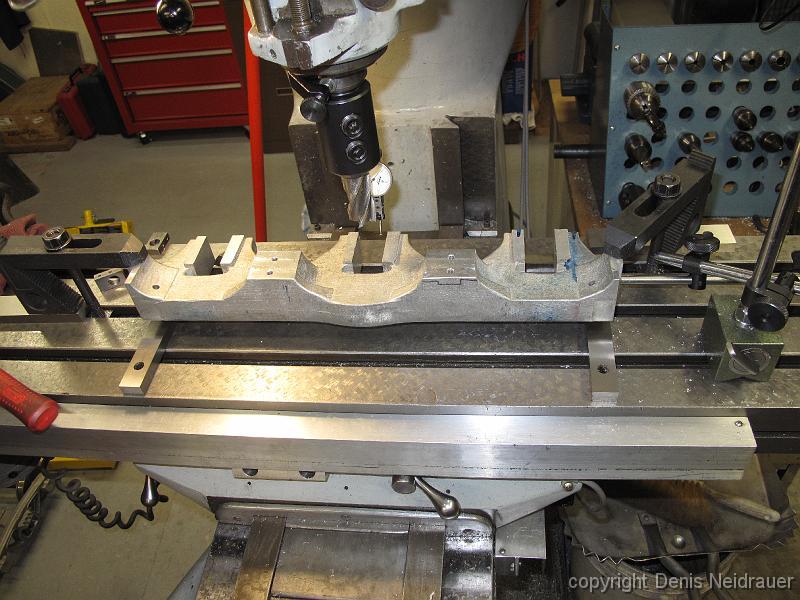
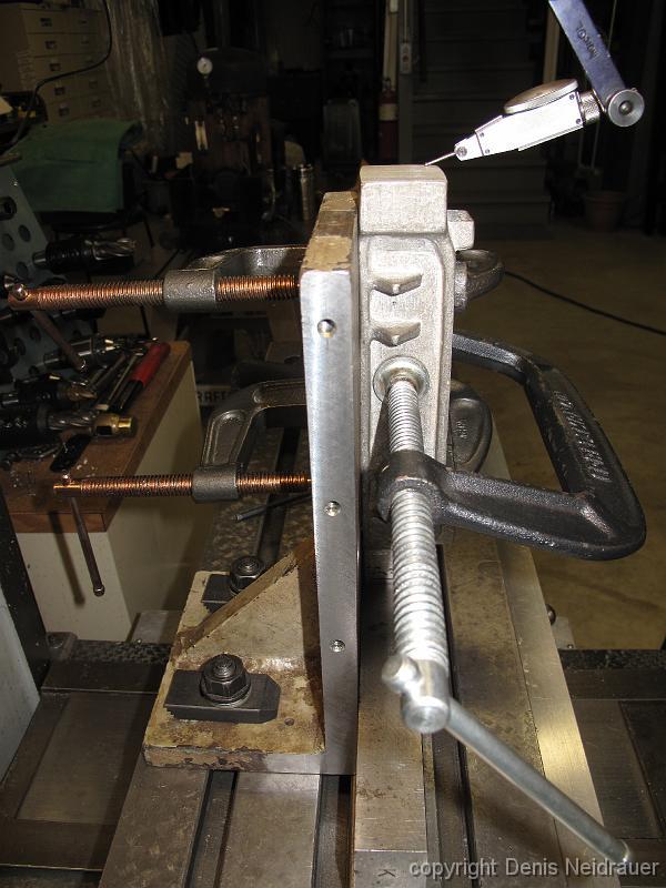
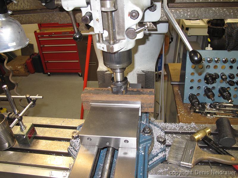
19-Nov-2012 Second cut: flip casting over and clamp on machined surfaces. use dial indicator to see how warped/level the casting is, also check it after…
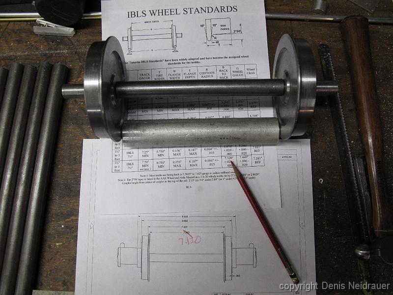
"From the railhead up". The only known finished dimension I have for the trucks is the distance between the railhead. Starting with that, I work my way up to…
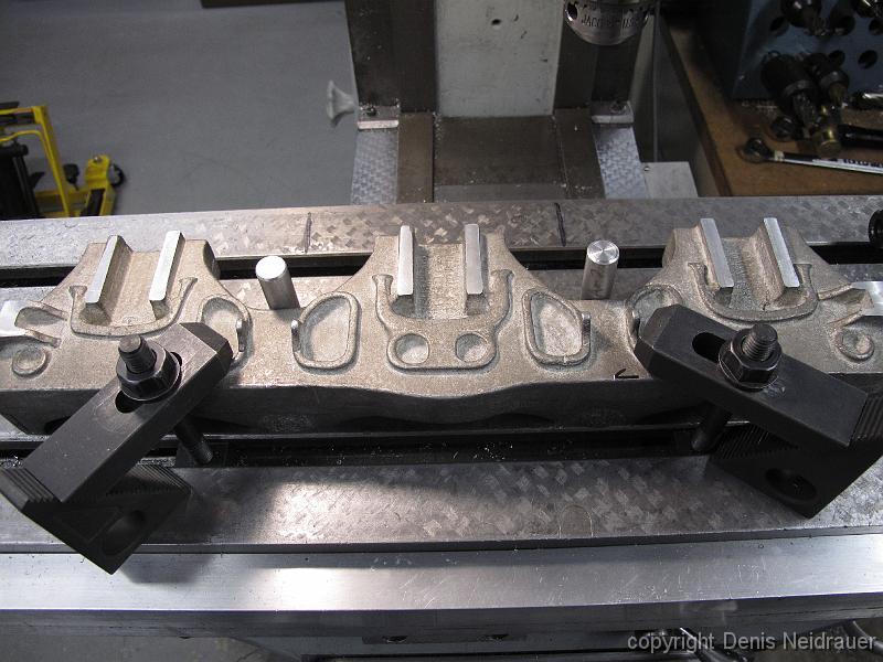
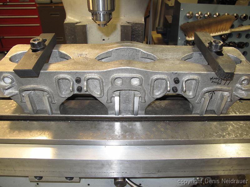
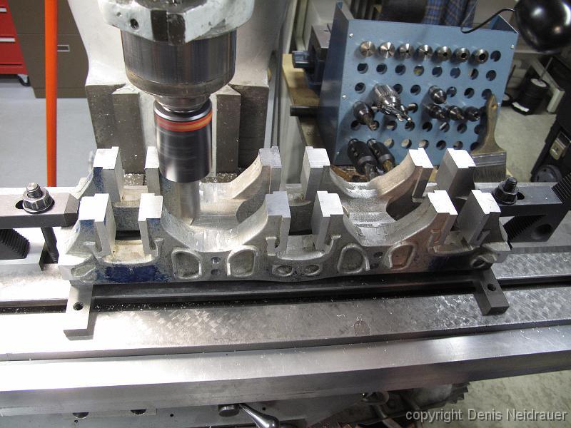
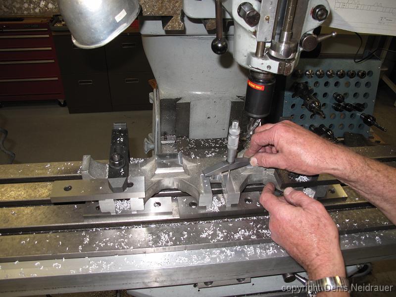
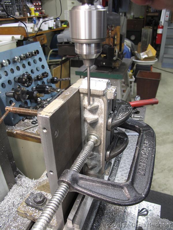
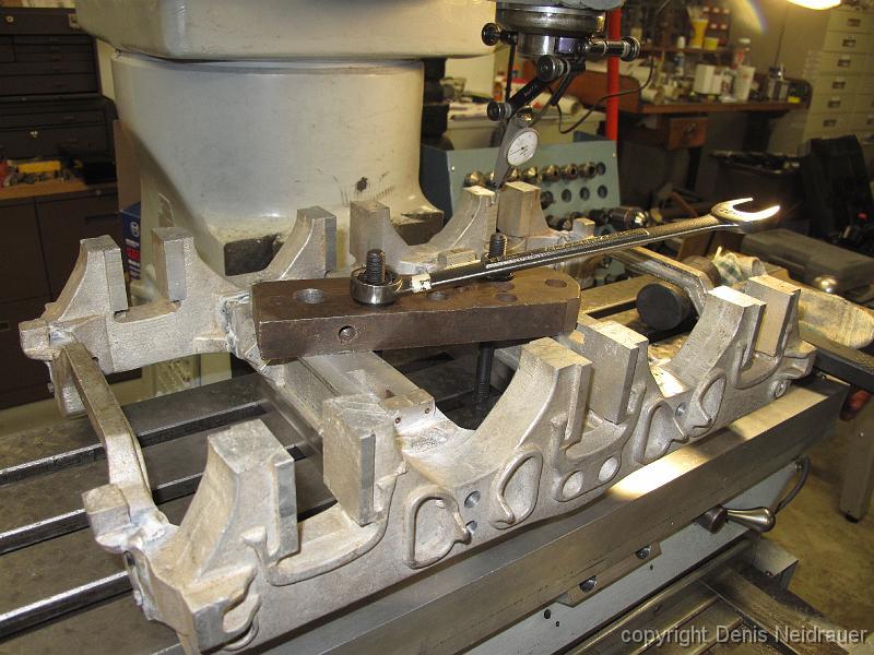
10-Dec-12 Third cut: flip the casting back over onto the machined surfaces to rough mill the axle box openings, rough trim the casting ends to length and set…
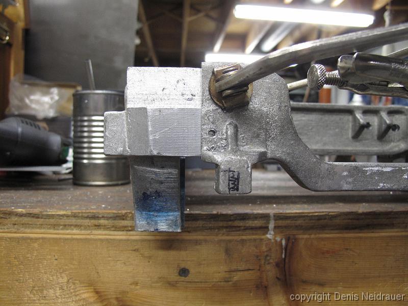
10-Dec-12 A lot of set up for two small marks. (black arrow pointing to scribe mark next to right toe clamp.)
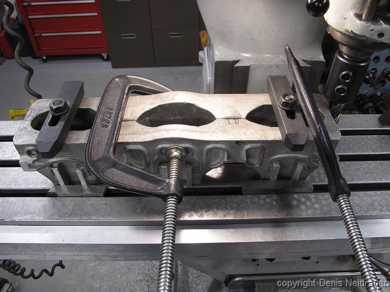
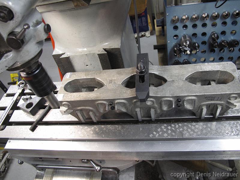
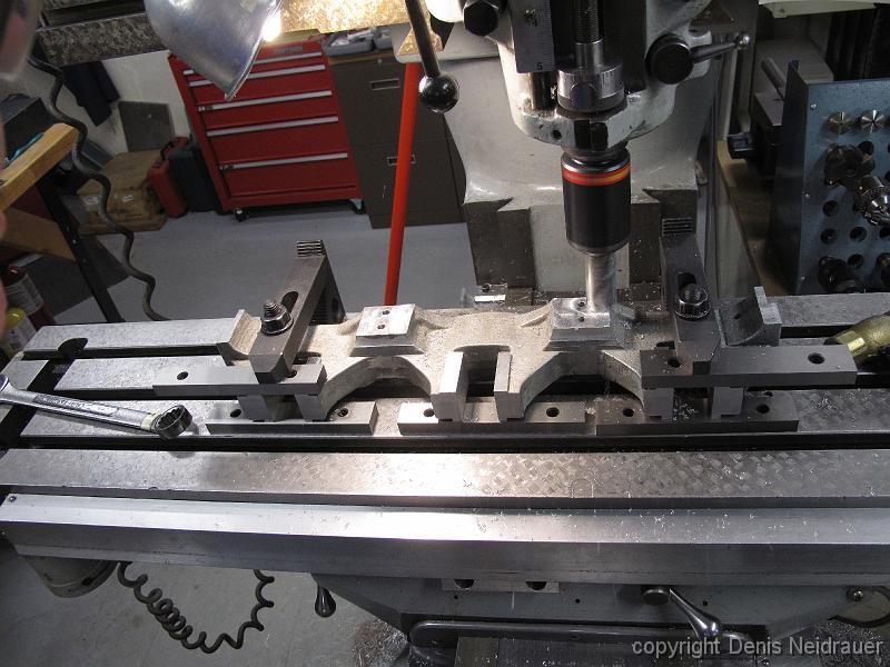
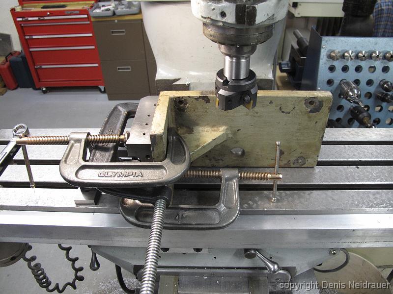
17-Dec-12 Last shop workday of the year. A couple of keys are put into the table slots and a pair of frames are bolted together, then bolted down to the table…
17-Dec-12 With each pair of castings a known length (both are different since one set was partially machined), and with a machined surface on the end, we can…
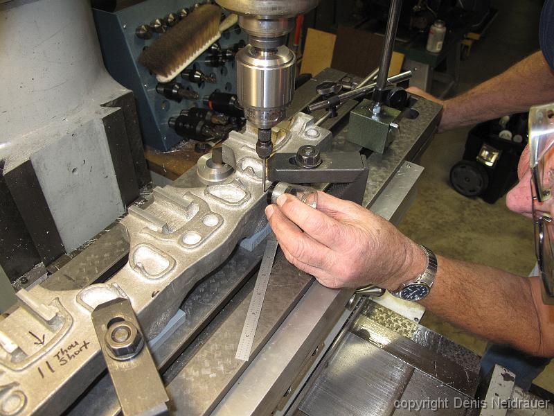
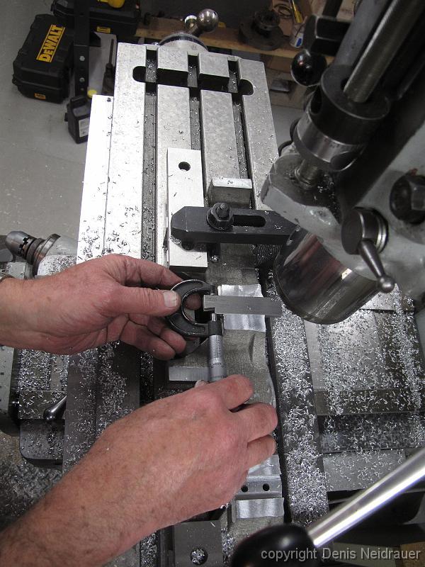
17-Dec-13 Using the pointed wiggler and a magnifying glass to pick up our reference mark.
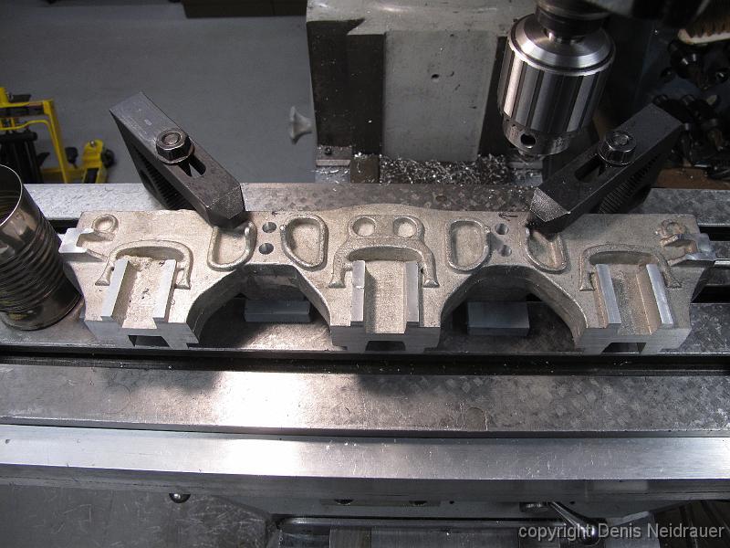
17-Dec-13 The other side of the frame after drilling and machining.
17-Dec-2013 Using the drilled and tapped frame holes, the pair of frames are bolted together and bolted down to the table. Next we will machine a reference flat…
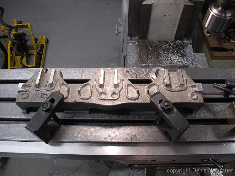
17-Dec-12 With dowel pins in the table slots, the casting is bumped against the machined flats giving us a consistent measurement for each pair of trucks. We…
7-Jan-13 The start of a new year, and we start on the other set of partly machined trucks.
7-Jan-13 Machining the reference surfaces into the trucks.
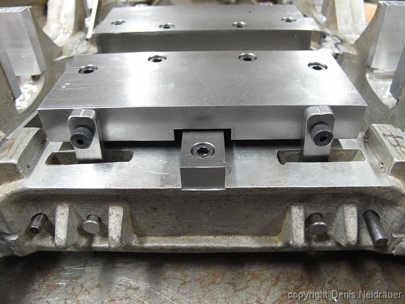
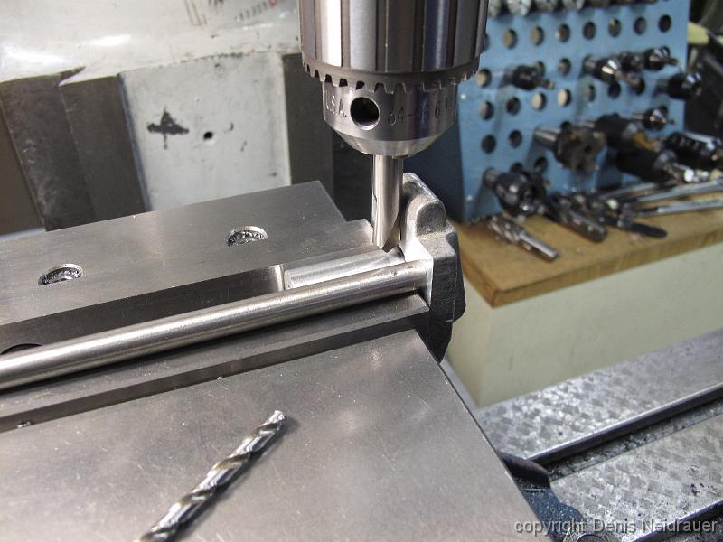
14-Jan-13 We start on the frame spreaders. Step one, machine a flat surface onto the bottom for the first reference surface. We have a spacer block between the…
14-Jan-13 Having machined two flat surface, the top and the two bosses on the side, we strategize our next move - how to machine the ends.
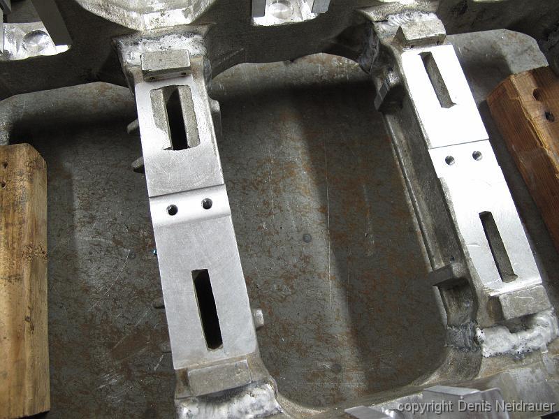
21-Jan-13 With the set of drawings I have created, we machine the frame mount points to the finished height.
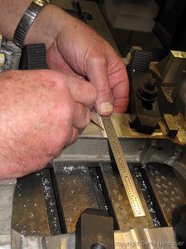
28-Jan-13 Using adjustable parallels to measure the slot ("a key") in the frame mount points. We want this to be accurate since this is the only mechanical…
4-Feb-12 As I did not have a large enough angle plate, Bill borrowed one from his friend Rick. We clamp it an inside angle plate and true up the edges.
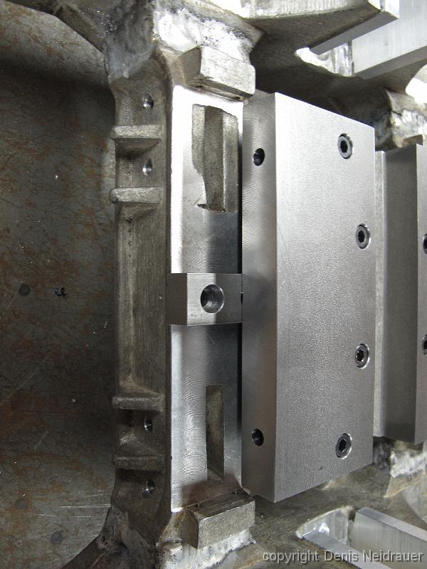
11-Feb-12 We have bolted a machined tool steel block to the side of the angle plate, giving us an inside corner. Now we can clamp the 9" long castings again two…
11-Feb-13 The clamping setup. The holes in the edge of the angle plate are so we can bolt the piece of tool steel to the other side, giving us an inside angle…
11-Feb-13 Checking the results of our work. The frame spreaders came our pretty close, within two thou and with no more than two thou taper across the ends.
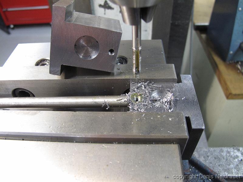
18-Feb-13 After drilling and tapping the mounting holes, and the brake hanger holes, we machine the Key bosses.
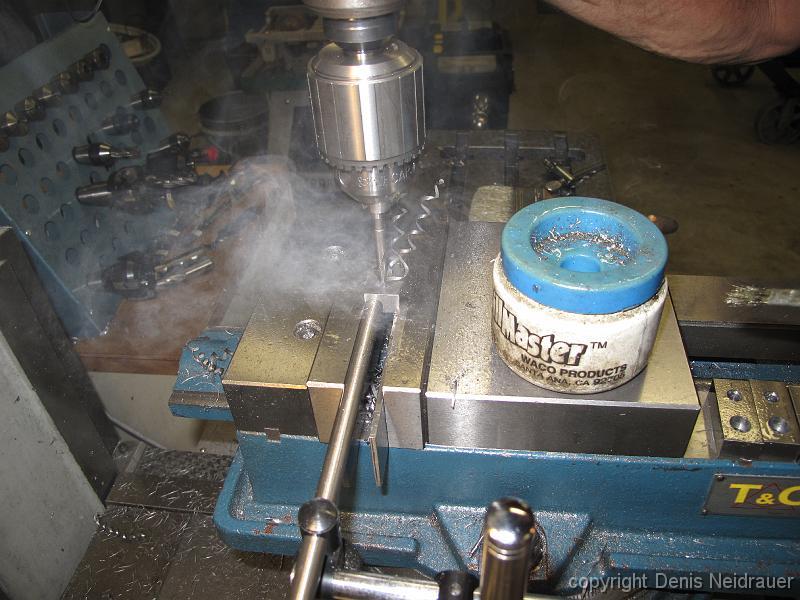
25-Feb-13 Drilling the holes for the swing link retaining pins. We had to mill a small clearance recess in the end of the casting to drill the holes.
4-Mar-13 Lacking blueprints for these castings, we use dividers to measure the cast-in dimples (which are not very visible) distance for the swing link pins to…
4-Mar-13 The drilled frame spreader casting. The holes outside the swing link pins will be for brake rigging, another puzzle to figure out.
11-Mar-13 On to the next puzzle: how to the end brackets attach? And how to machine the curvy end brackets?
11-Mar-13 The finished clamping fixture with drilled and tapped clamping points, end bracket in place.
18-March-2013 Milling the pocket recess for the end bracket, showing the clamping set up. We have clamped over the machined surfaces of the pedestal faces. We…
25-March-2013 We decide to match drill the bolt holes of the end brackets into the frame. Drill and tap one hole, insert bolt and tighten, then remove the clamp…
25-March-2013 I was so excited to see the truck frame bolted together after three years of pondering and designing!
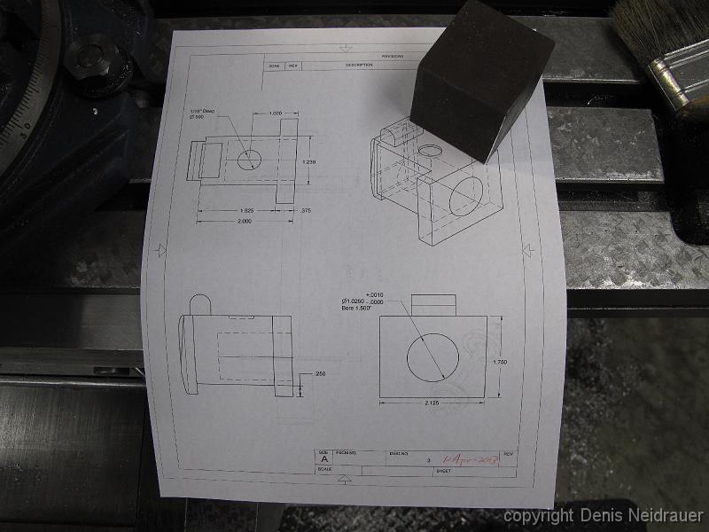
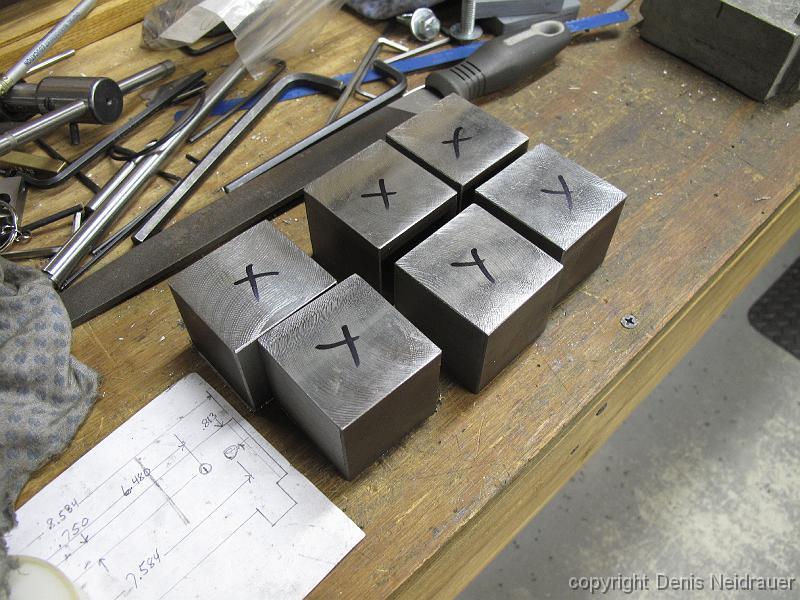
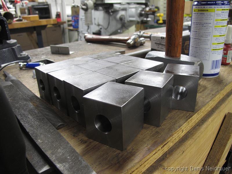
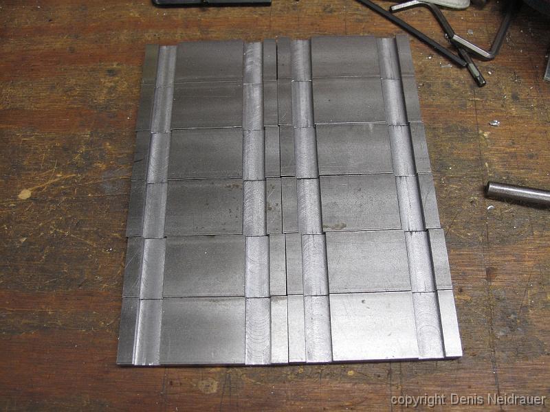
1-Apr-2013 Latest drawing for the axle boxes. I put the cut-off bandsaw to long duty and cut twelve pieces of 2x2x2 steel. We will use steel instead of the cast…
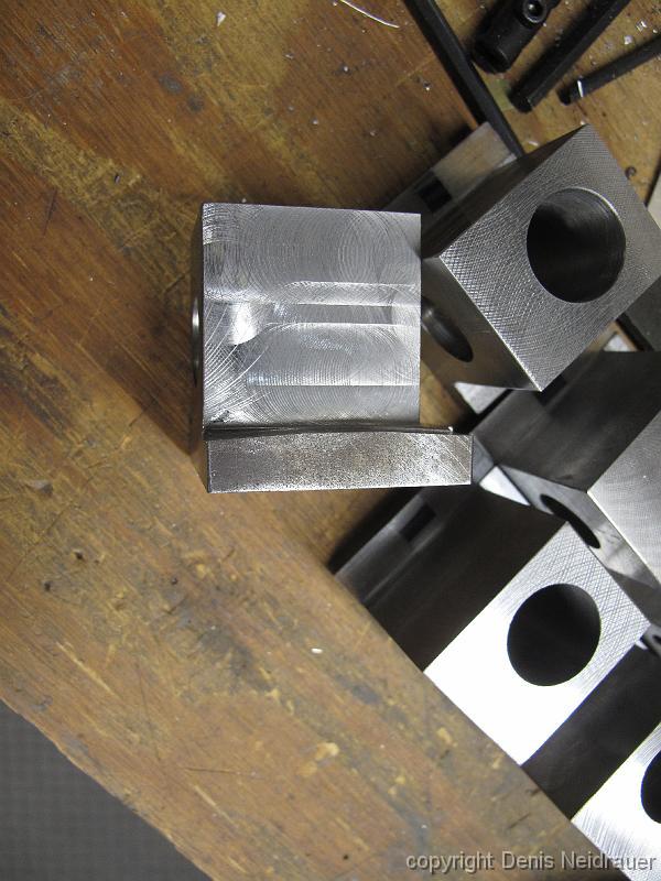
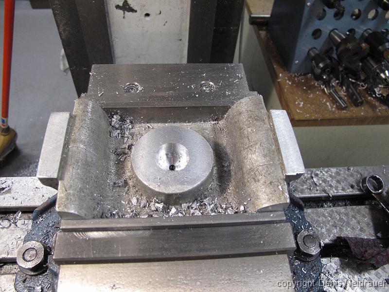
8-Apr-2013 After making one clean up cut, the block is rotated in the vise with the machined surface against the fixed jaw, and the next surface is skim cut.…
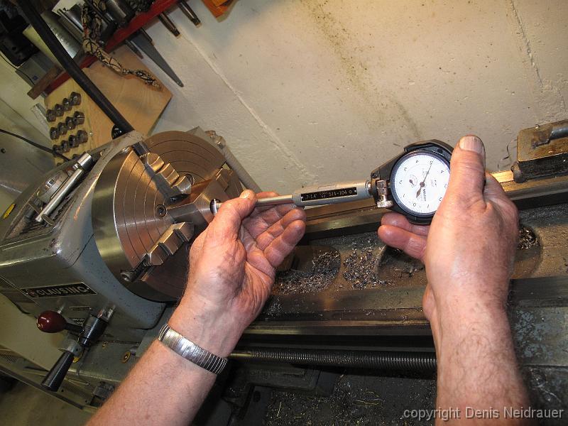
15-Apr-2013 Knowing the exact dimensions of the bearings, we bore the axle boxes to a -0.0005 press fit. Bill uses a bore gauge to check dimensions.
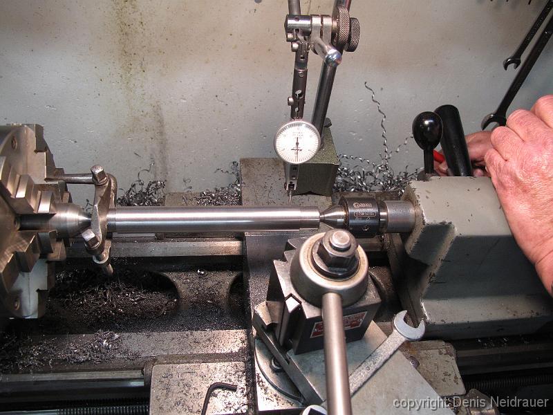
6-May-2013 Bill turns a mandrel between centers to a close fit for the axle boxes. Here Bill is moving the tailstock over to remove the taper from the cut,…
6-May-2013 ?Why machine a mandrel? We will put the mandrel through the boxes and rotate them around the center for the next machining operations, insuring all…
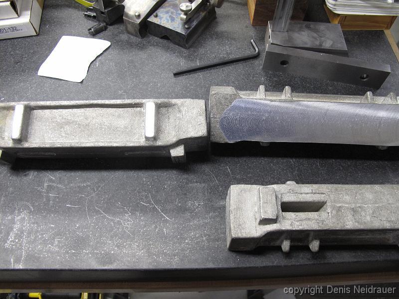
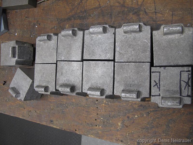
6-May-2013 I have spent more quality time with the bandsaw, cutting the cast aluminum axle boxes in half. We will not use these as axle boxes, but are trying to…
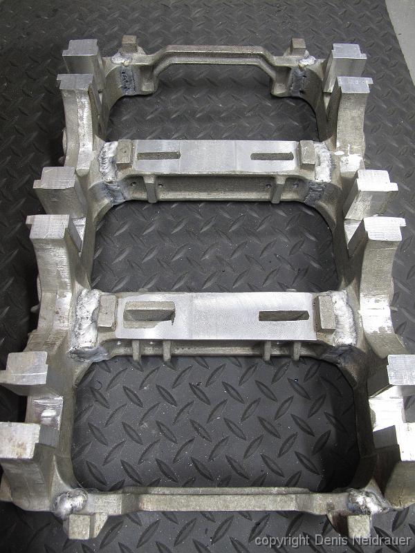
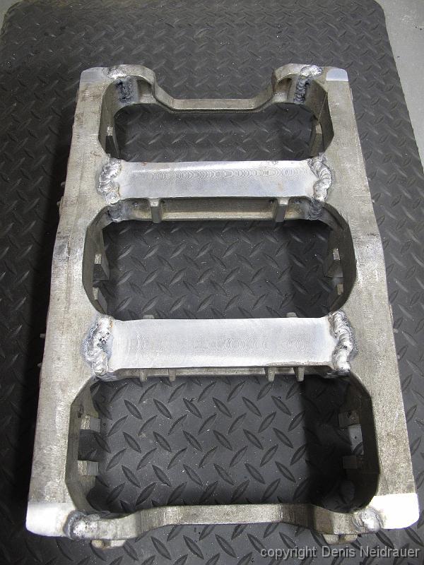
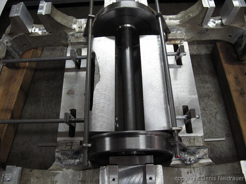
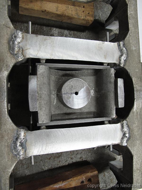
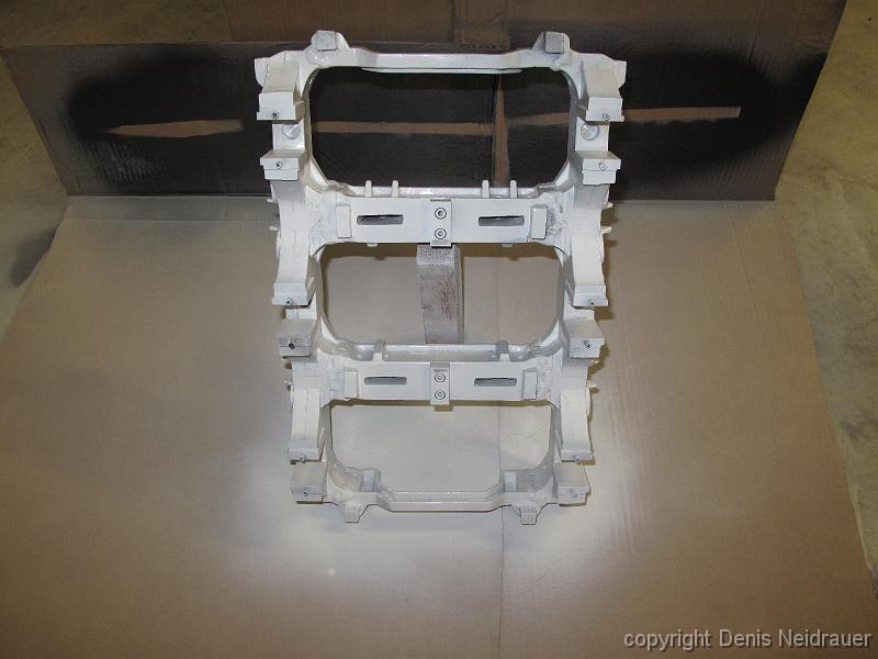
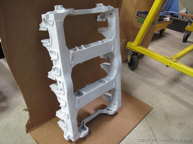
10-Jun-2013 The castings are back in the shop after a being out for a month at a friends shop who TIG welded all the joints creating a solid one-piece frame…
10-Jun-2013 Lacking tiny inside micrometers, Bill uses adjustable parallels to fit the opening and measures across it with the 2" micrometer.
10-Jun-2013 Picture of the TIG welds on the topside of the truck frame. The welder was not happy with the quality of the welds, but I was. The castings are…
17-Jun-2013 Last machining operations for this frame - milling a pocket for the axle spring, Drilling and tapping 6-32 holes for the pedestal binders, and…
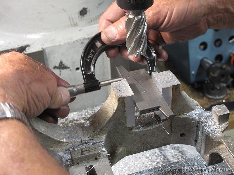
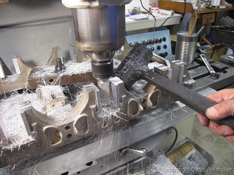
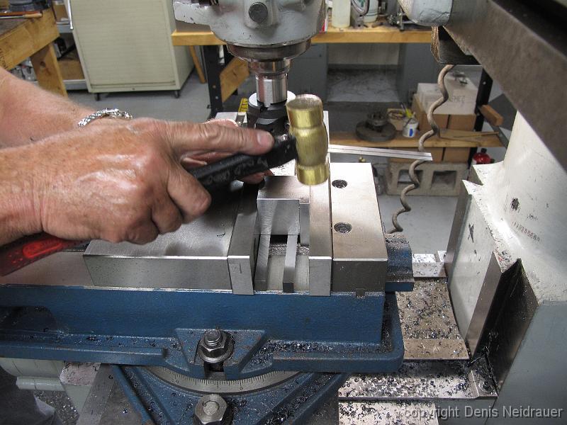
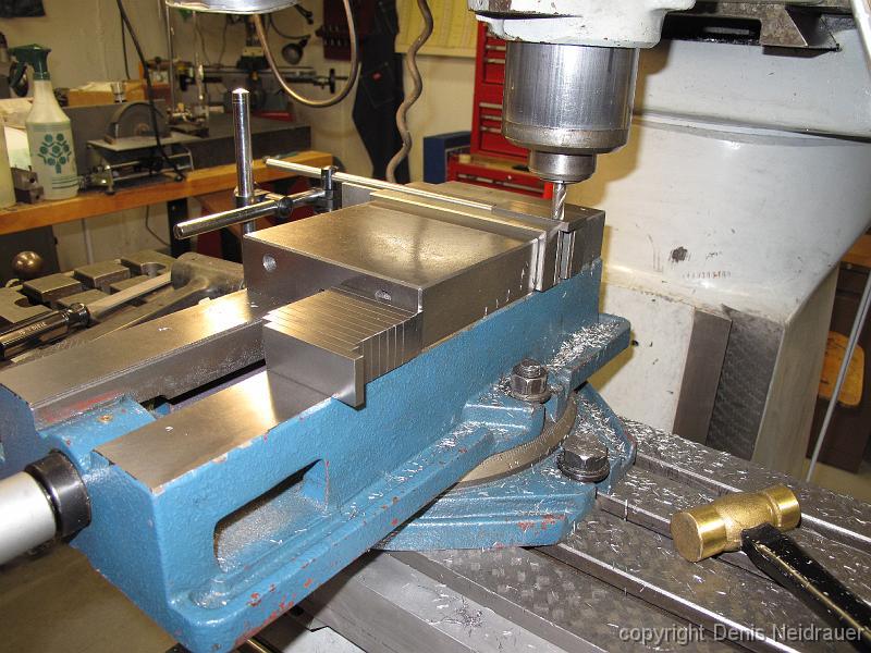
24-June-13 Machining the axle box openings to size. No, we are not pounding on the frame with the deadblow hammer. Bill is holding it against the frame to…
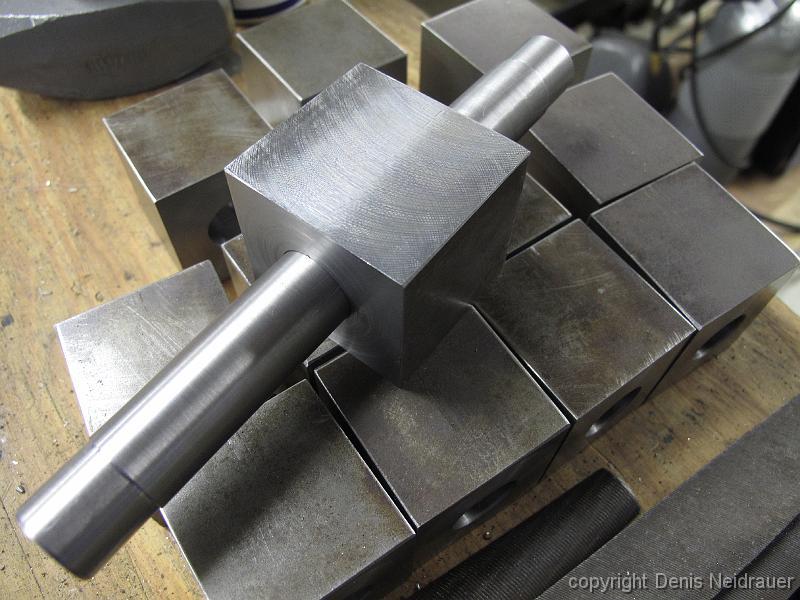
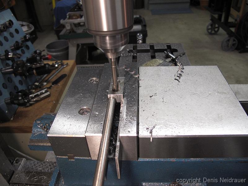
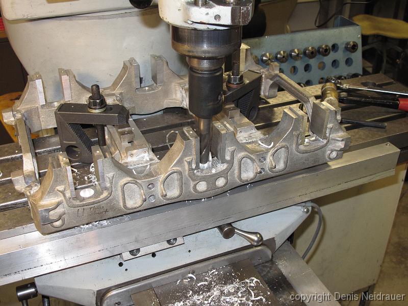
1-Jul-2013 Rough cutting the axle boxes. We use the round alignment mandrel to revolve the part around the centerline of the bored hole for each cut. Here the…
1-July-2013 We also decided not use the alignment mandrel for the roughing passes as we were having trouble making all the sides parallel with each other. Using…
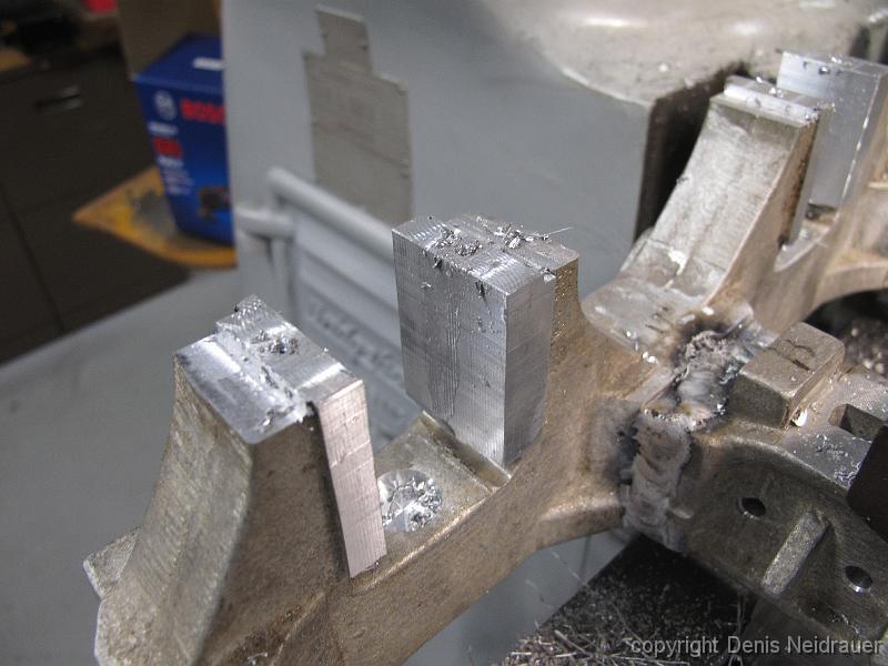
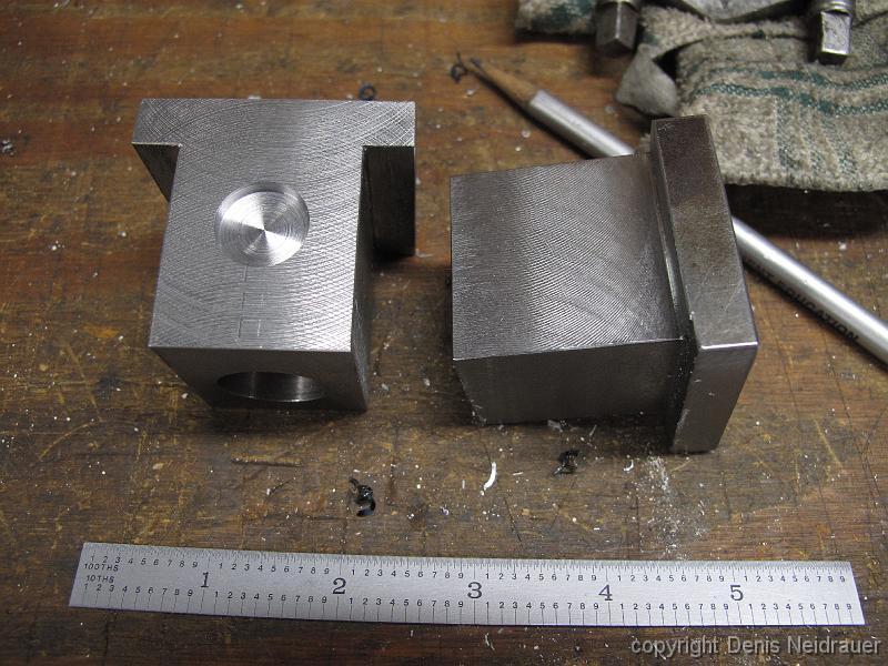
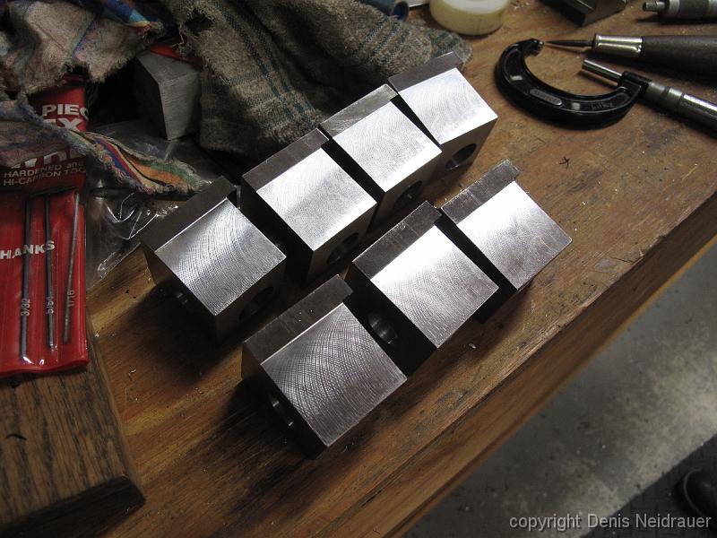
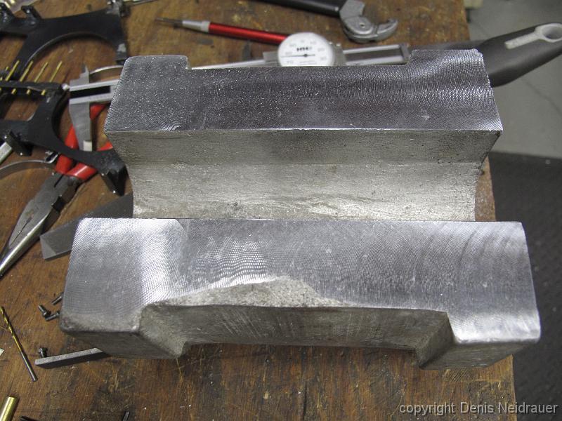
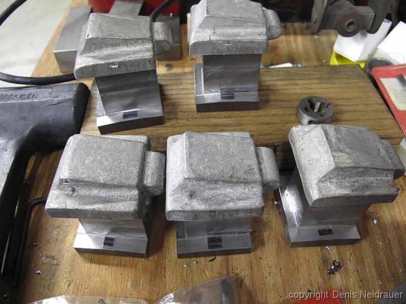
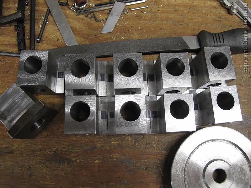
1-July-2013 Two axle boxes roughed out, with spring pockets recessed into the top, for a trial fit into the frames.
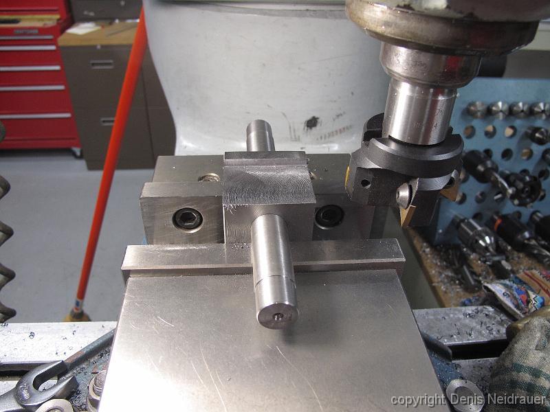
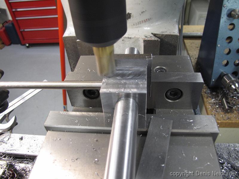
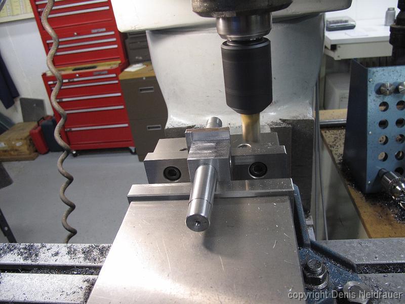
1-July-2013 Setup for finish pass machining the axle boxes to width. We will machine this one side, then flip the box around the mandrel and then machine the…
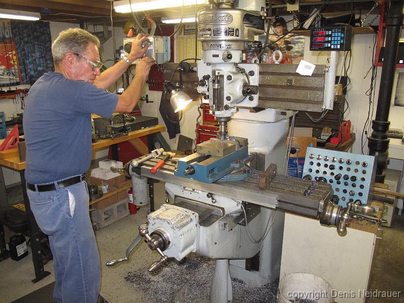
5-July-2013 A full work day in the shop! Bill has his hand on the X-axis table feed to power through the remaining 10 axle boxes (two test ones were previously…
1-July-2013 The row of roughed to width axle boxes grows throughout the day, as does the pile of chips on the floor.
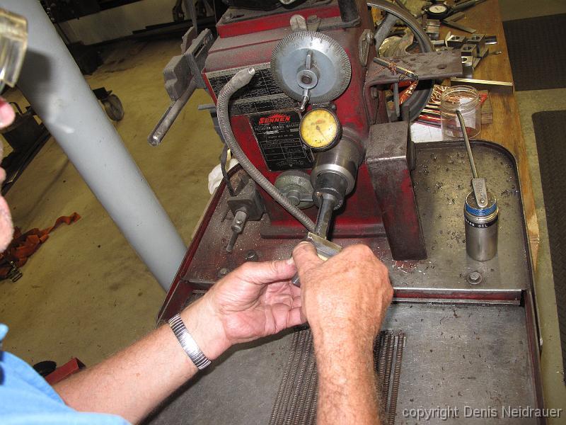
8-July-2013 Using the Sunnen pin hone with a mandrel borrowed from his buddy Rick, we make the bore holes truely round, without taper, and the same size to each…
8-July-2013 With the 1" micrometer in his hand, and a ball attachment on the end of the mic anvil, he measures from the inside bored hole to the finished width…
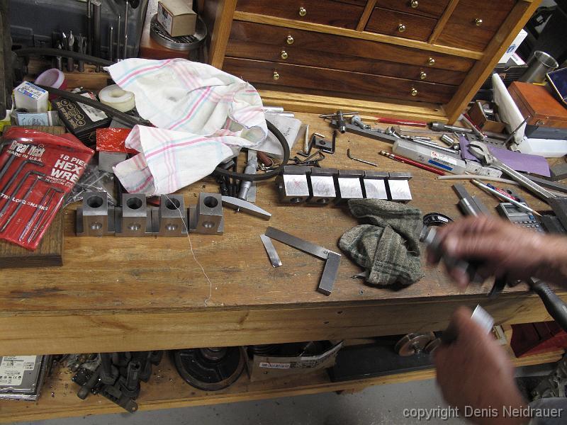
15-July-2013 The tabs of the axle boxes are machined with a taper on each side of center. This allows the axle to move up and down on uneven track without…
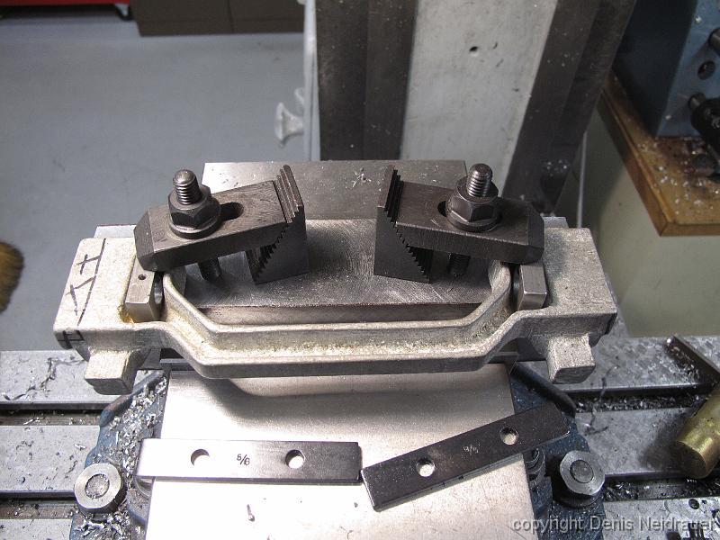
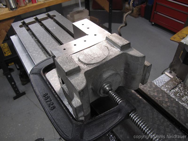
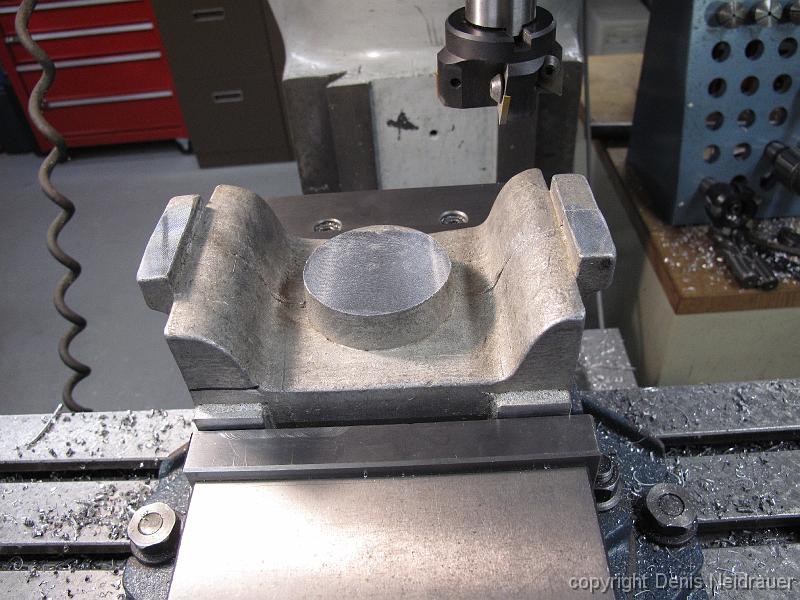
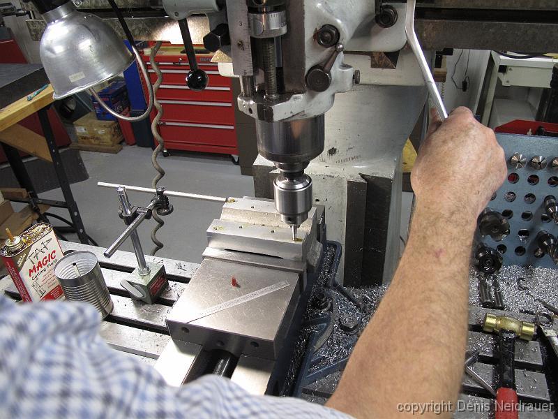
4-Nov-2013 After some discussion, we decide to clamp the bolster to the angle plate and take skim cuts on the bosses sticking up in the picture. After cutting…
4-Nov-2013 The bottom of the bolster is skimmed with a light cut deep enough to break through the skin and give a starting surface to start machining from.
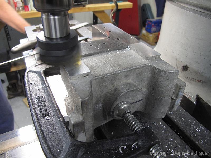
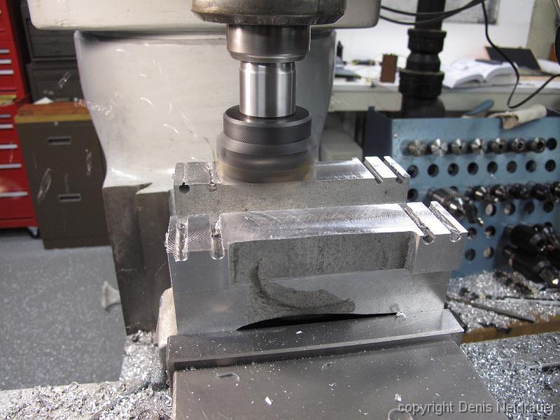
4-Nov-2013 Using the fly cutter to cut the rub pads to size. Goal is to have the pads on the other side (in the picture, they are on the bottom on the table)…
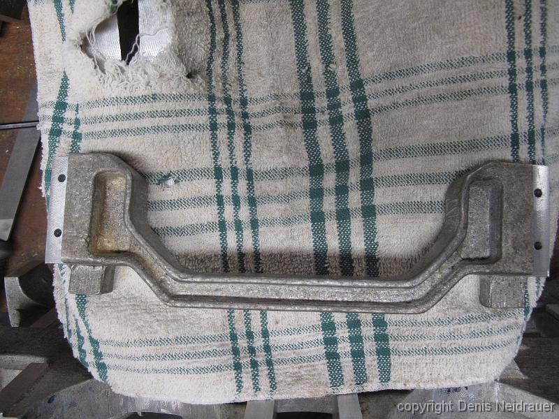
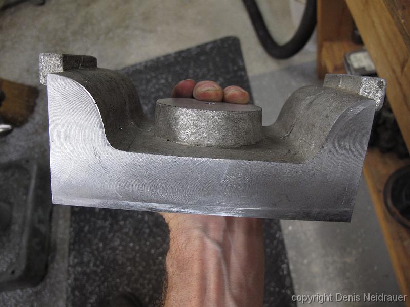
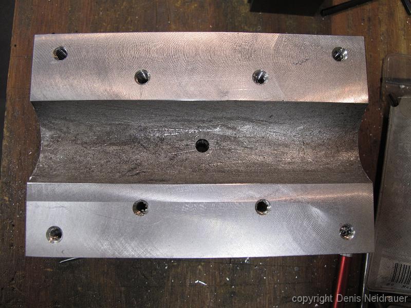
4-Nov-2013 With the bolster machined so it fits into the truck frame, I get to see how the frame might sit on the frame. I really can't tell though, because I…
11-Nov-2013 We have made one set of temporary swing links, and drilled 1/4" holes completely through the bolster. The length of the links and location of the…
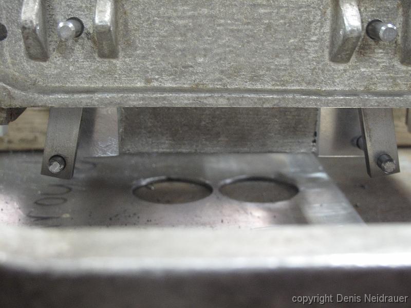
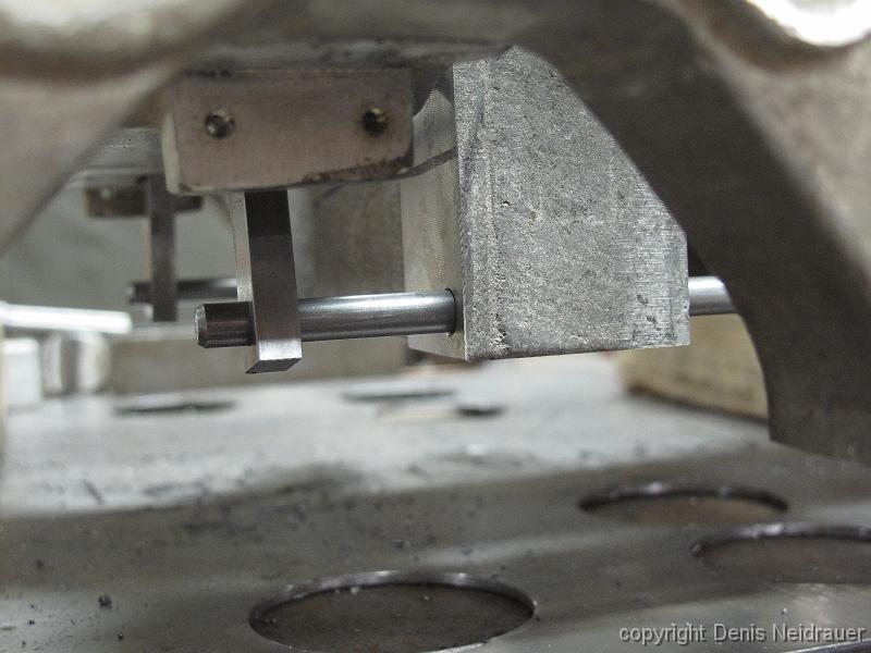
11-Nov-2013 Looking at the swing links. We are trying to figure out how far apart the bolster link holes should be compared to the frame holes. We drill the…
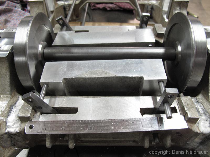
18-Nov-2013 With the truck on it's back, and with another set of test holes drilled in the swing links we are much happier with the way the bolster moves. We…
11-Nov-2013 Machining the binders in a familiar set up for multi-operation steps -- A stop in the vise to locate each part in the same place.
25-Nov-2013 The slot in the binders has ben machined, next to drill clearance hole for the binder screws.
27-Nov-2013 Interference and motion check with bolster, axle, wheels and brake mechanism. This is a complicated little space and we have no prints go guide us.
27-Nov-2013 Our only blueprint for the brake rigging is an entry from the 1922 edition of "The Locomotive Cyclopedia of American Practice"
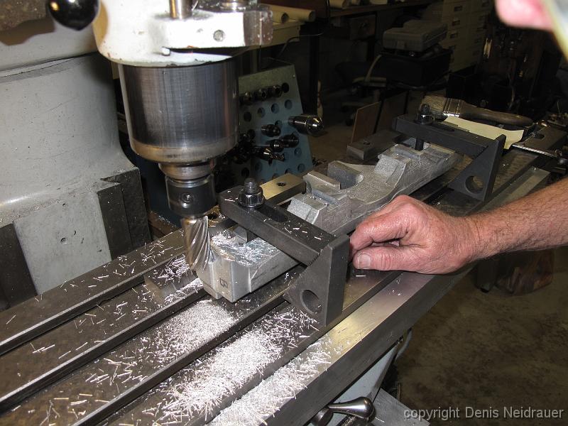
7-Dec-2013 Castings can be a pain to work with -- All the cuts are relative to each other. In this case, what is the reference surface we should use to measure…
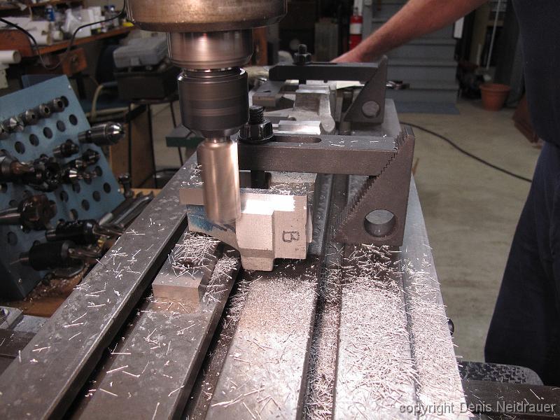
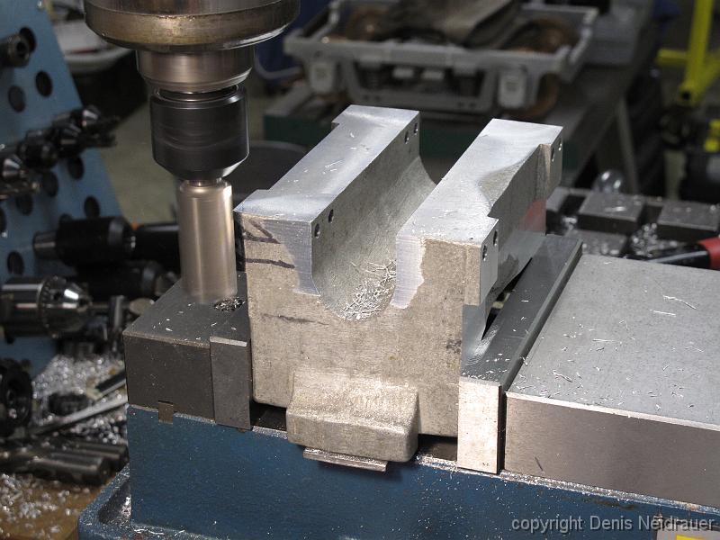
7-Dec-2013 Using the previously cut center boss as a reference, we true up the side ends of the bolster.
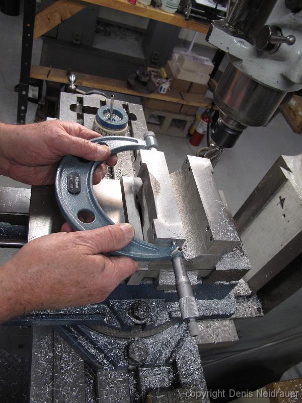
7-Dec-2013 Checking the overall width of the bolster with a 6" micrometer. We had previously made a mark indicating the center of the part to make the left and…
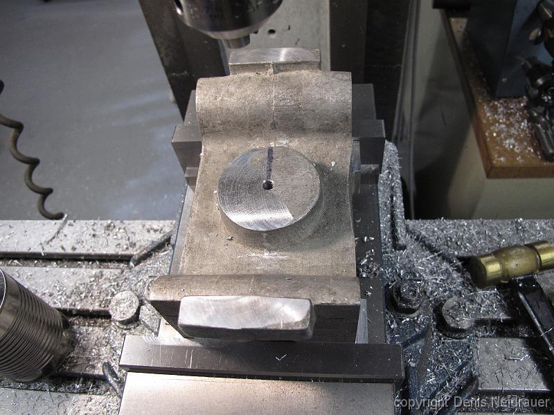
7-Dec-2013 With the ends machined and the vise at the limit of its 6" capacity, we center the part and drill a reference hole for a close fitting dowel pin.…
7-Dec-2013 We have been pondering for some time how to overcome an design gap with the cast bolster. The bolster is smaller than the position of swing links…
7-Dec-2013 After machining away the bottom of the bolster casting, it is much smaller and lighter, at least for now.
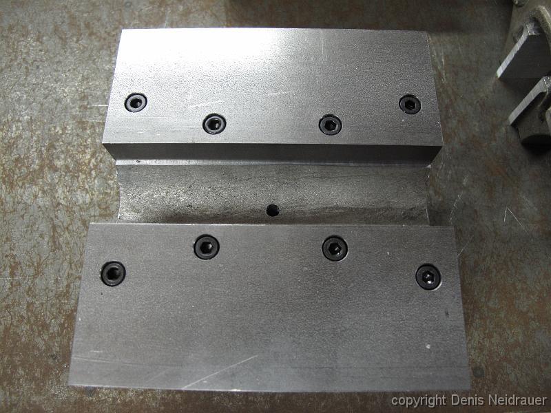
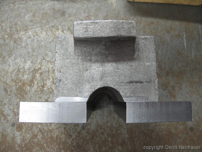
9-Dec-2013 End view of he Bolster Swing Link Extension blocks bolted to the bottom of the bolster. The swing links will touch the left and right side of the…
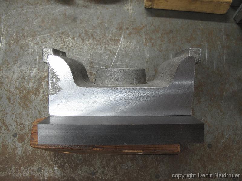
9-Dec-2013 Side view of the Bolster Swing Link Extension blocks bolted to the bottom of the bolster.
16-Dec-2013 Having discovered the bolster could travel side to side and interfere with the brake rigging, we have to design a stop into the bolster motion to…
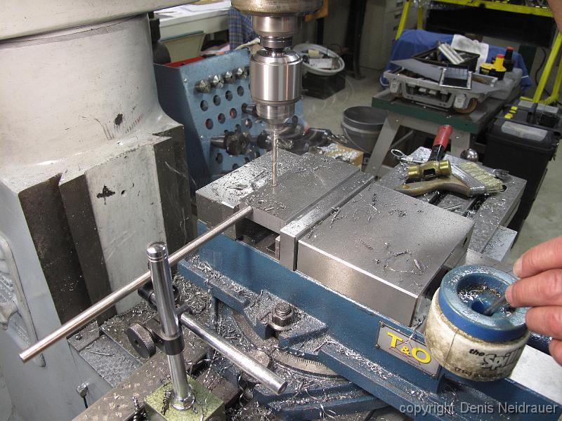
16-Dec-2013 Drilling and counter-boring the stop blocks. Again, the vise stop is employed for this multiple step operation.
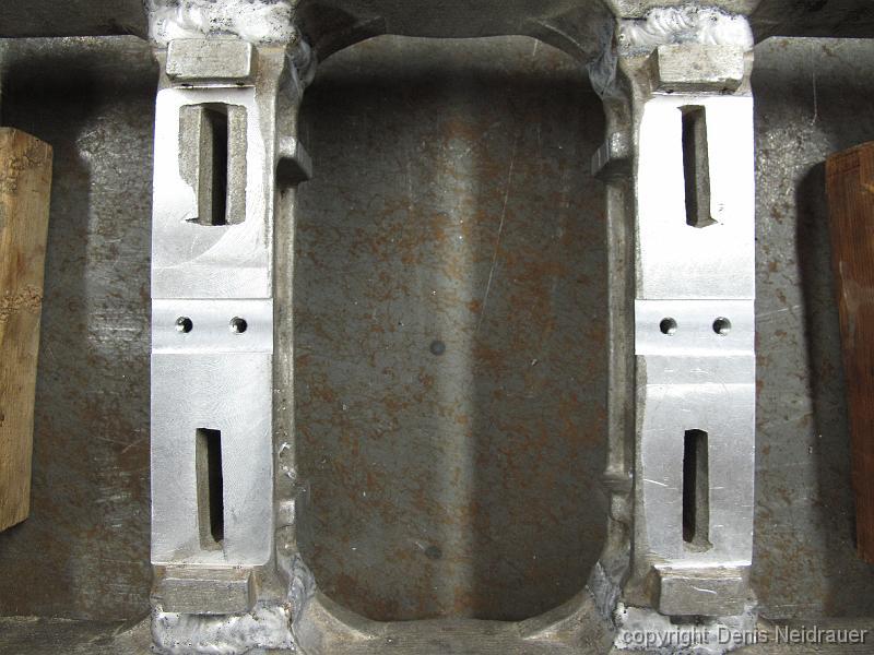
16-Dec-2013 The frame spreaders with a close fitting slot for the stop blocks and tapped 10-24 holes
16-Dec-2013 The frame spreaders with a close fitting slot for the stop blocks and tapped 10-24 holes.
16-Dec-2013 With the stop blocks installed, we have to figure out how big a slot to cut in the Bolster Swing Link Extension Block to set the amount of travel.
16-Dec-2013 The bolster travel limit blocks installed on the frame and the corresponding slot cut in the Bolster Swing Link Extension Blocks, assembled for…
16-Dec-2013 Top view of bolster with the bolster travel limit blocks installed on the frame. You can also see the rub plates installed on the side of the…
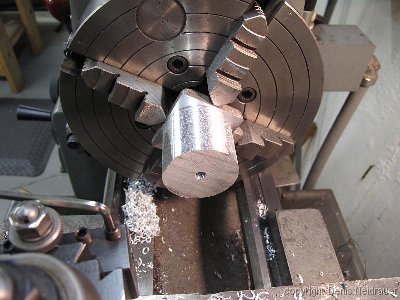
4-Jan-2014 Bill begins turning down the 12 Axle box cover castings. There is very little of the casting to hang onto in the 4-jaw chuck, and determining the…
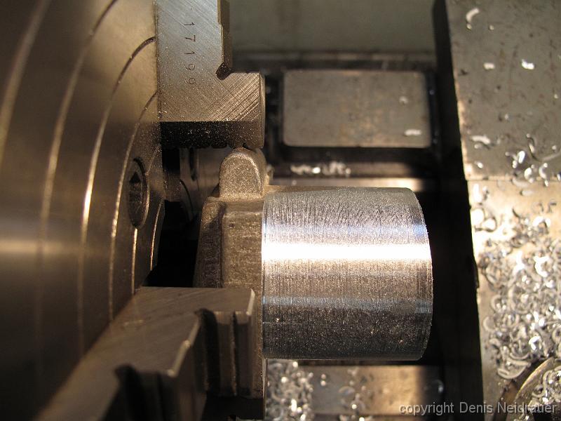
4-Jan-2014 Trial fitting of the cover in the box. The axle box cover stub is a good fit into the bored hole in the axle box.
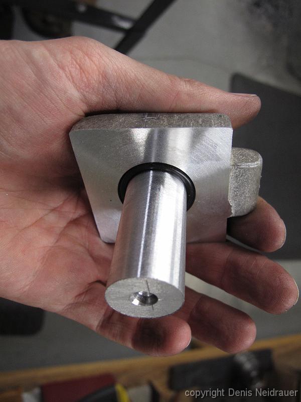
4-Jan-2014 Axle box cover with turned stub and O-ring groove. Cutting the groove required grinding a special tool to cut next to the stub and into the cover…
18-Jan-2014 You would think I'd have this all figured out by now, but sure enough, the draftsman (me) made a dimensional error on the wheel spacing. Fortunately…
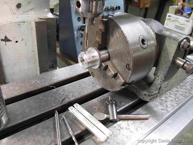
18-Jan-2014 The spindle stop installed on the lathe. This allows us to chuck up parts in the lathe repeatably. When the part is put into the chuck, it is…
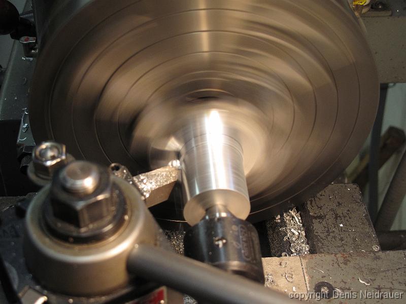
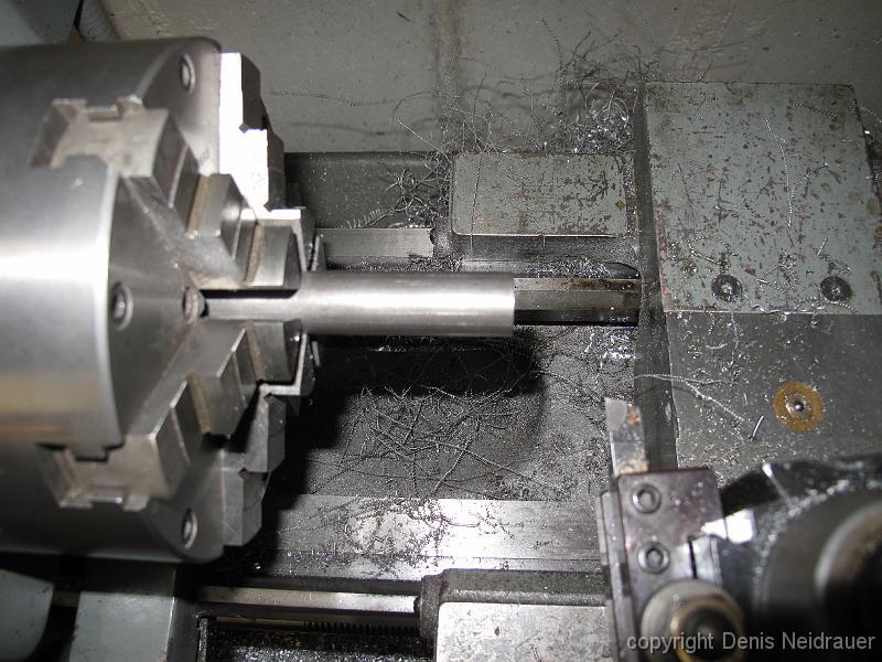
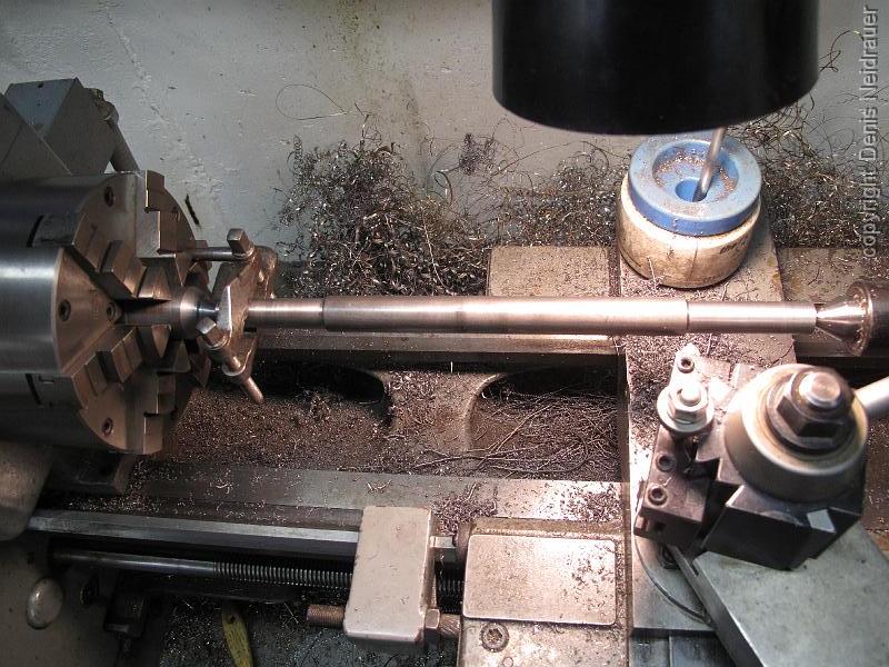
18-Jan-2014 With the axle inserted into the chuck against the spindle stop, we the axle down to the bearing diameter, cutting the length until we bump against…
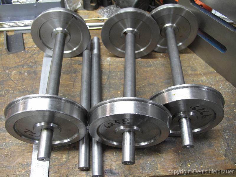
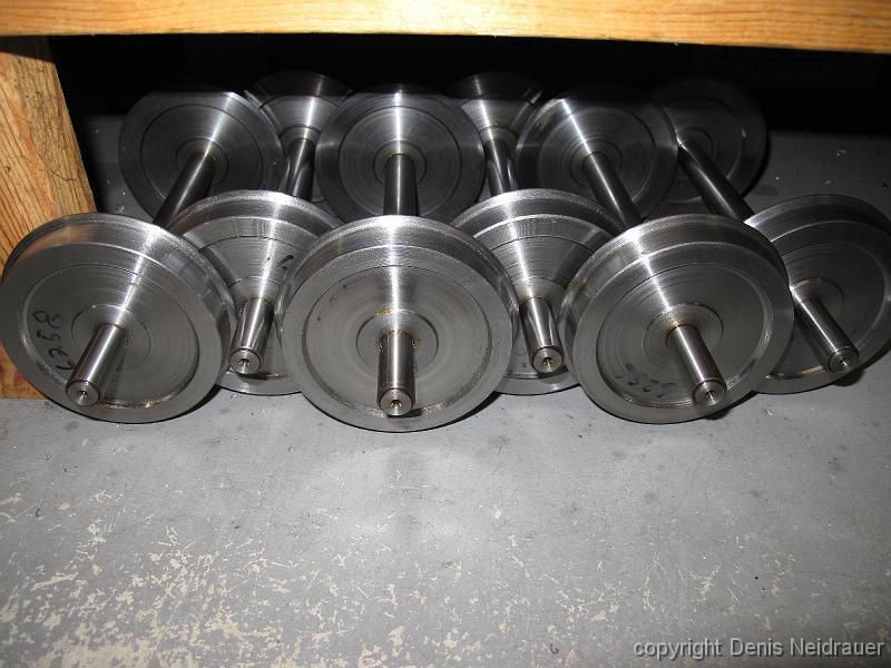
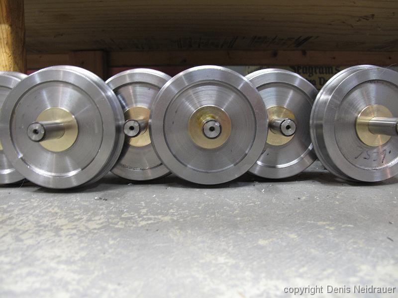
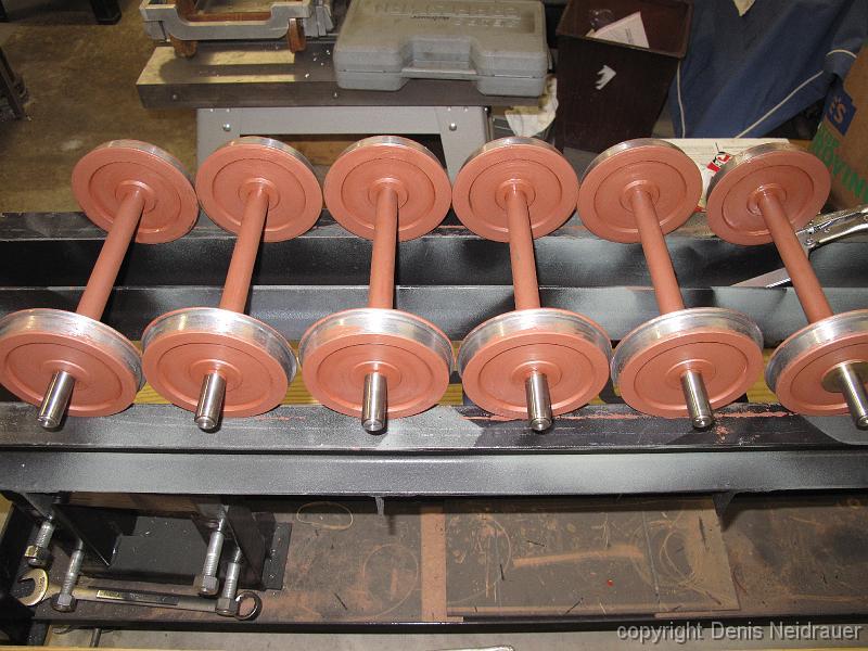
20-Jan-2014 Wheels pressed on axles! Despite our best efforts, equipment and machining variabilities result in wheel bores which vary by +- 0.0015 from each…
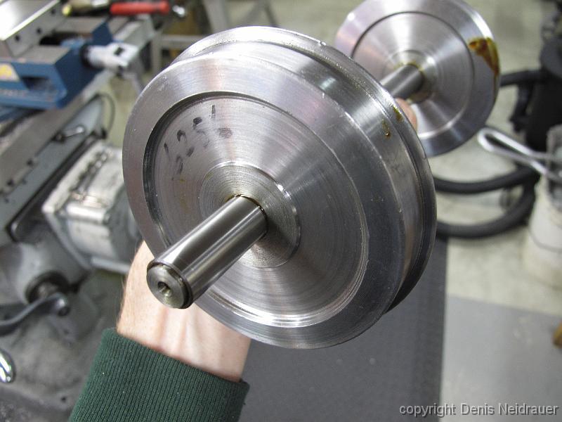
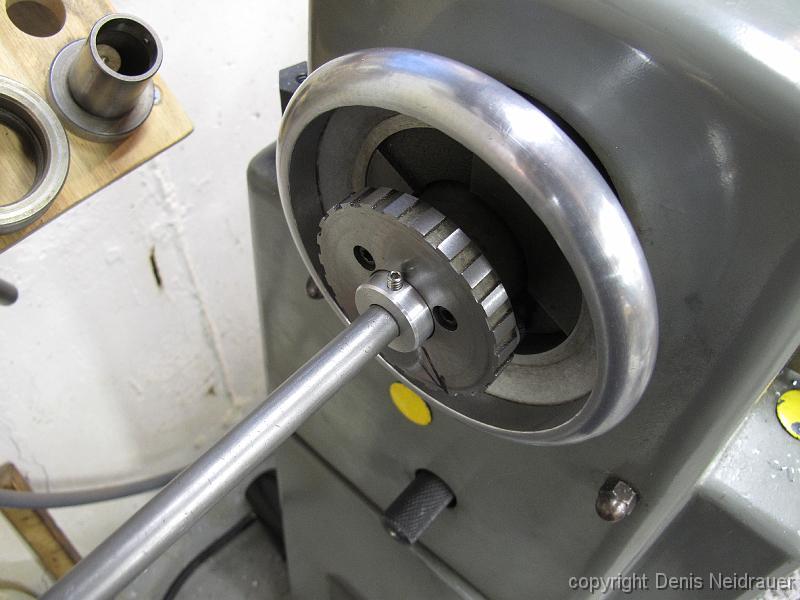
25-Jan-2014 With months of creating parts, it's nice to do assembly. We have pressed on a hardened thin drill sleeve onto the end of the axle. This gives the…
1-Feb-2014 Drilling a spot for the set screw anchor in the axle box cover castings. Note the vise stop is not on the stub end of the casting but the reference…
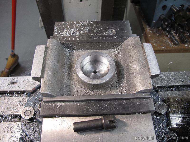
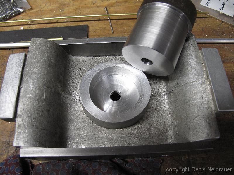
3-Feb-2014 We start enlarging the center hole for the 1-3/4" kingpin. We move through a series of progressively larger endmills before switching to the boring…
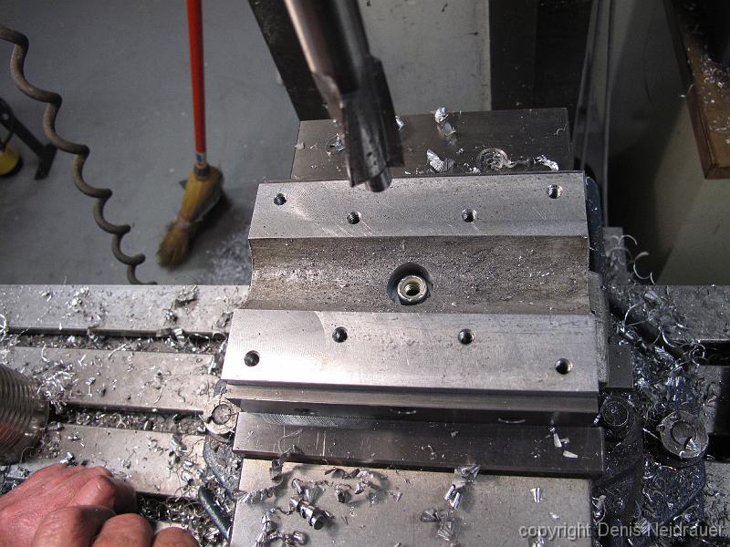
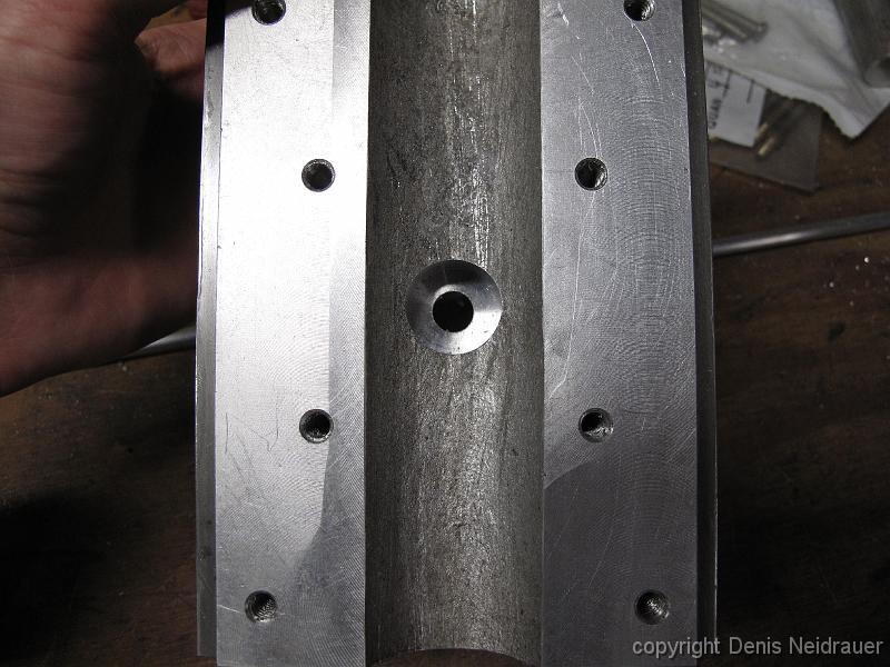
3-Feb-2014 The bottom of the bolster is counterbored so the kingpin binding nut does not interfere with the axle.
15-Feb-2014 We turn 12 brass thrust washers and install them on the axles. We did not want to have the steel wheel rubbing on the steel axle box as the wheels…
15-Feb-2014 After a trial installation of the springs, we decide they are too compressed in the unloaded state. The truck frames are bolted to the mill table…
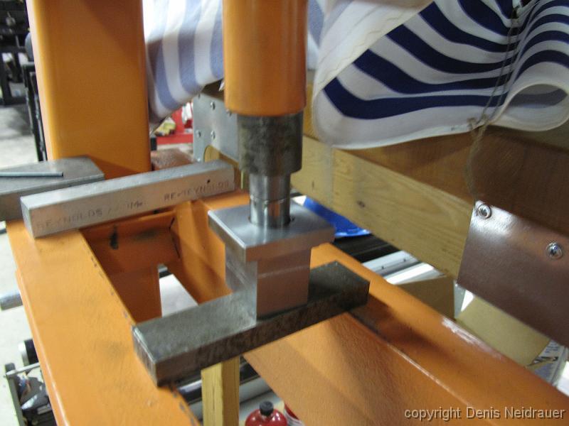
15-Feb-2014 Pressing the bearings into the axle boxes. Bill turned a piece of stock for the press guide.
15-Feb-2014 Axle boxes with lubricated bearings installed on the axles. Due to the machining variations resulting in different amounts of press on the bushings…
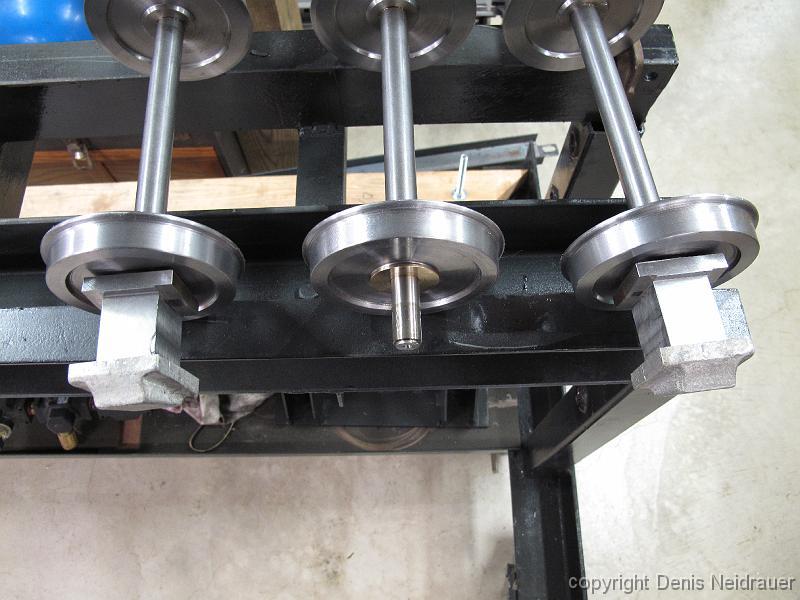
15-Feb-2014 The end of one nights work: nearly assembled truck ready to be flipped over for its first test roll.
9-Dec-2013 Sometimes a pencil and paper drawing will suffice. Here Bill has laid out the bolt hole pattern for the bolster swing link plate.
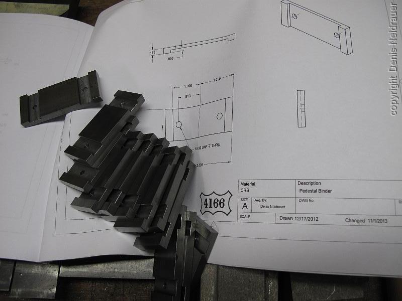
27-Nov-2013 Finished binders. On the drawing I created, the center portion is machined away to allow for more axle box travel. Bill wanted to captivate the ends…