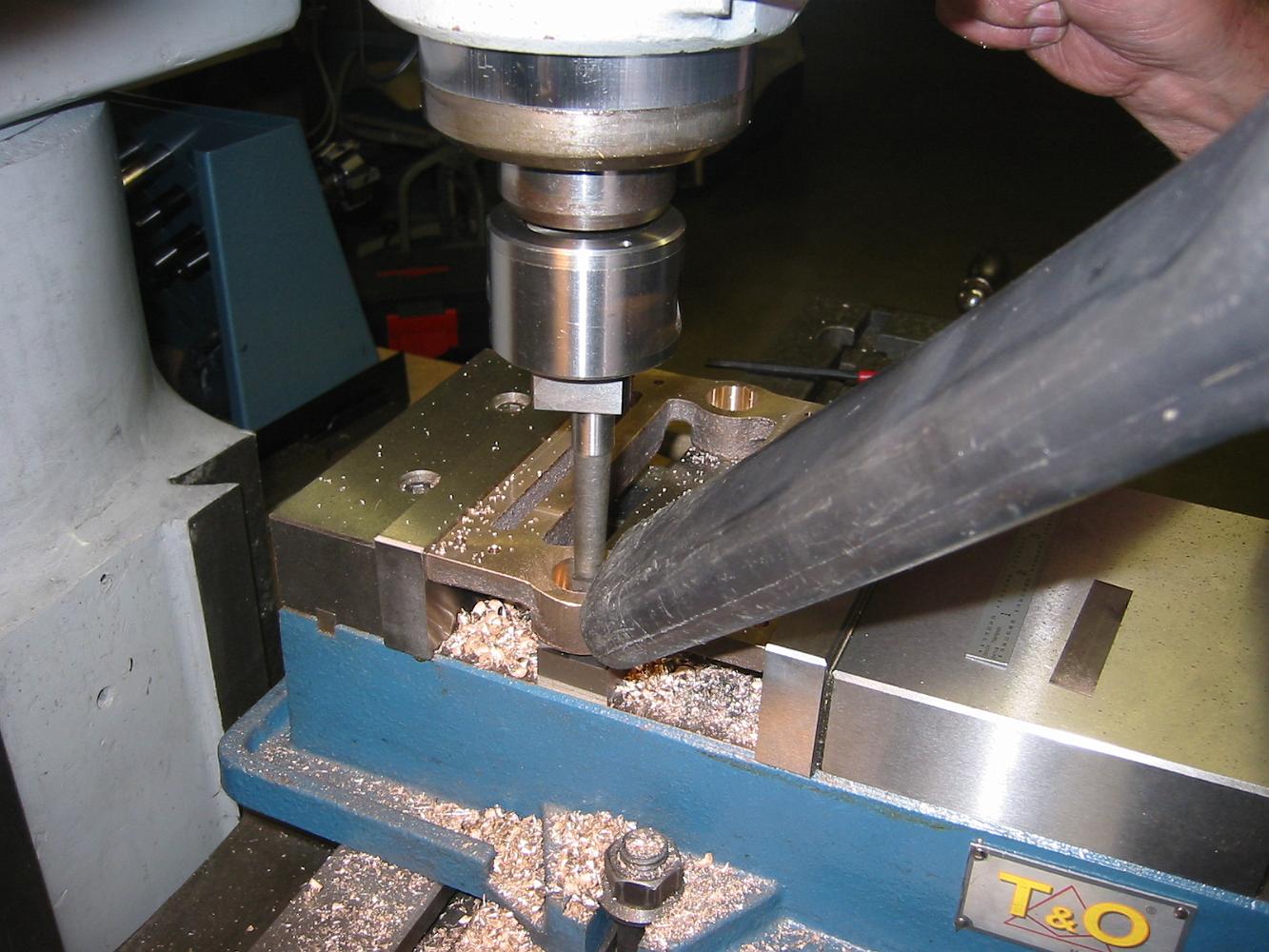
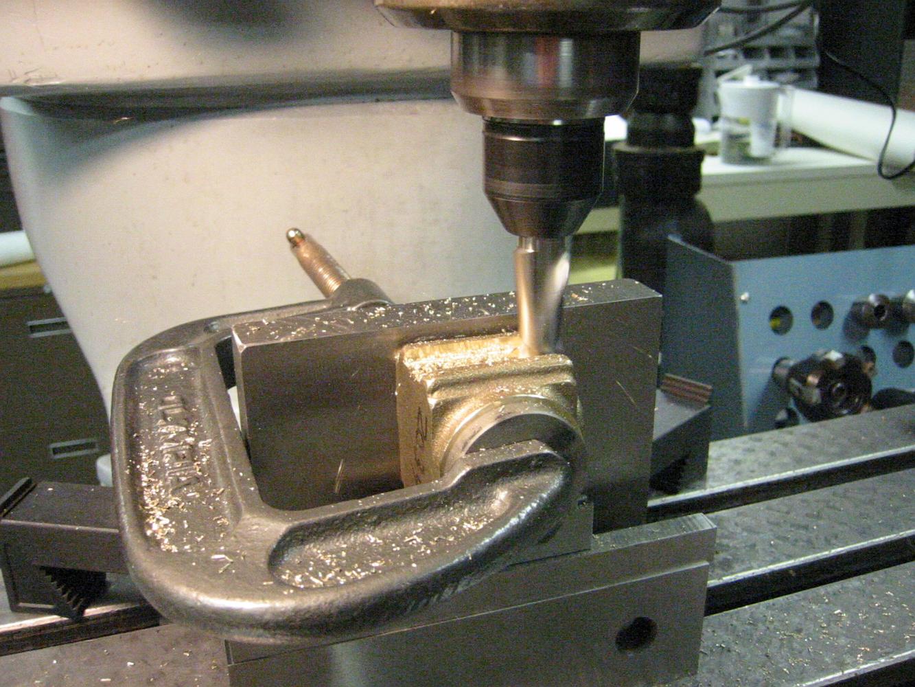
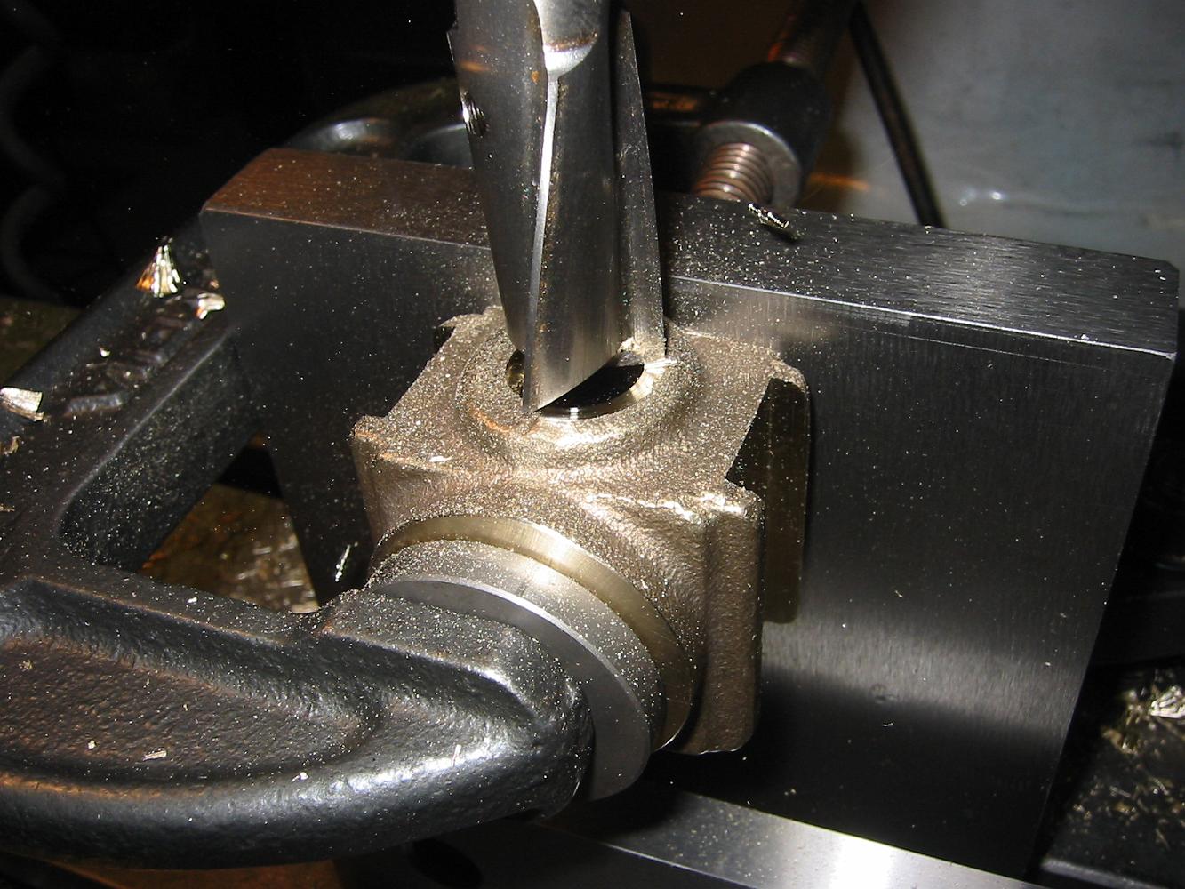
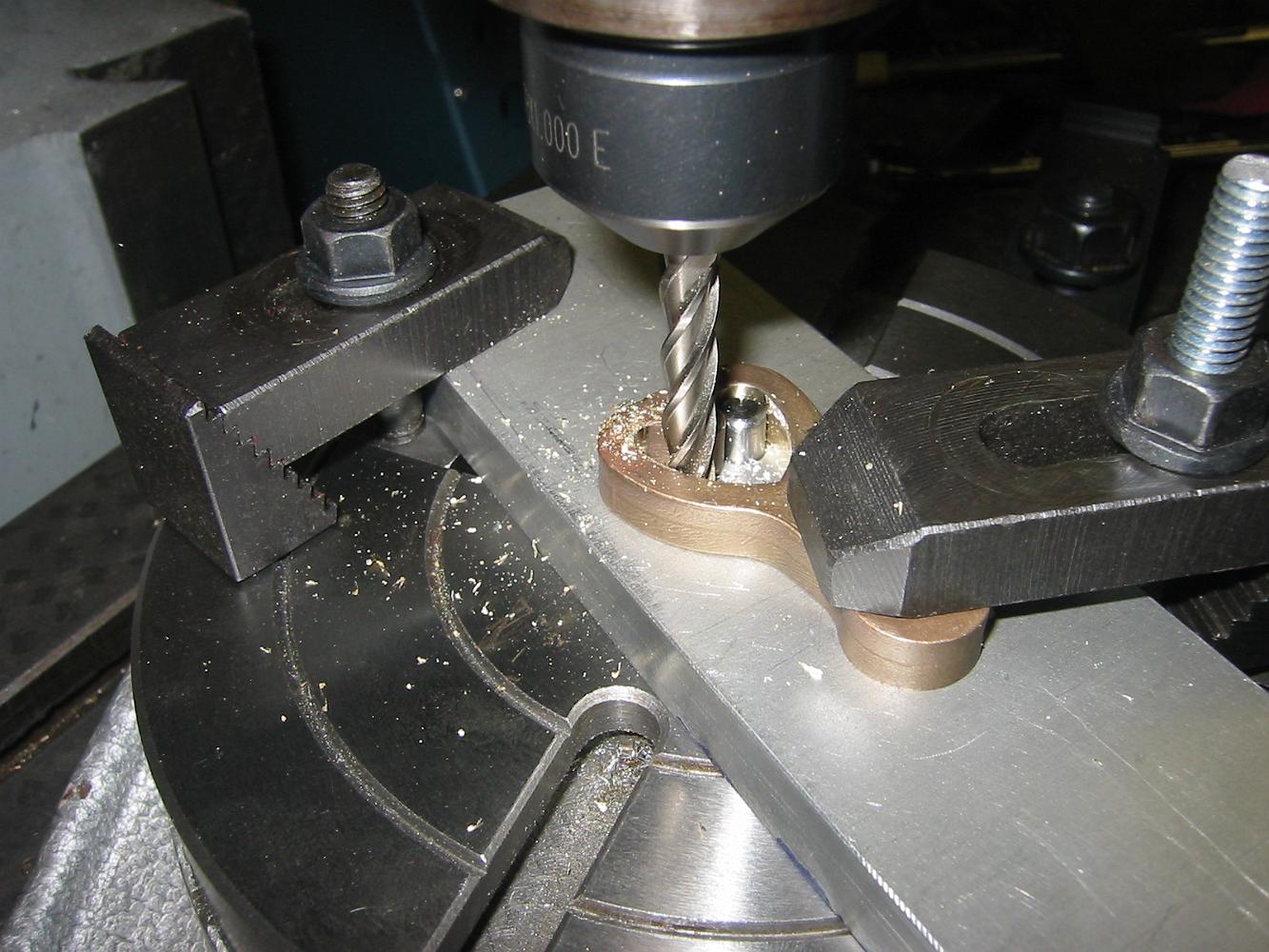
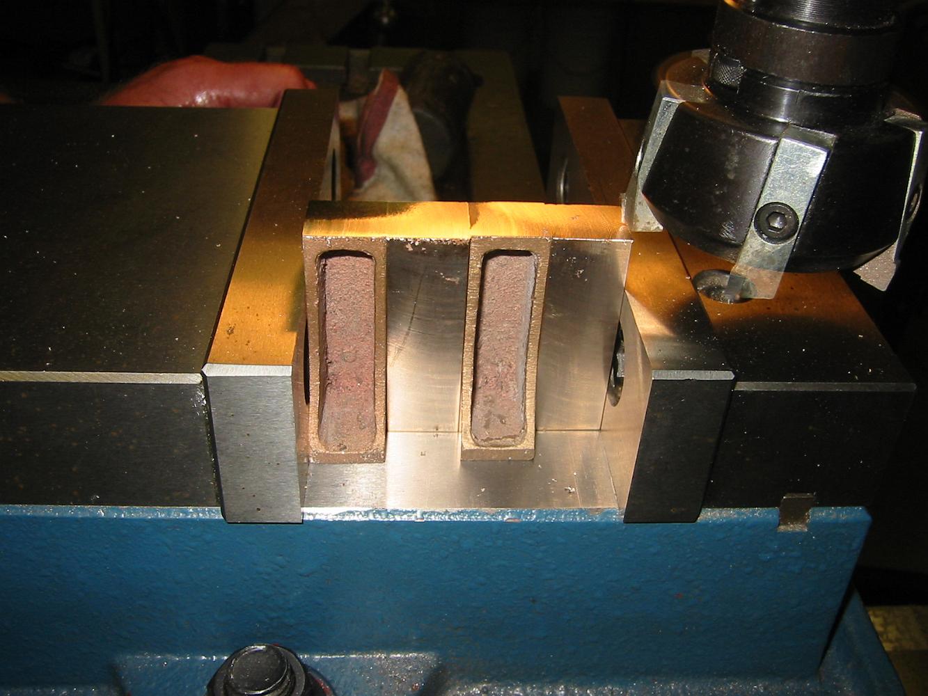
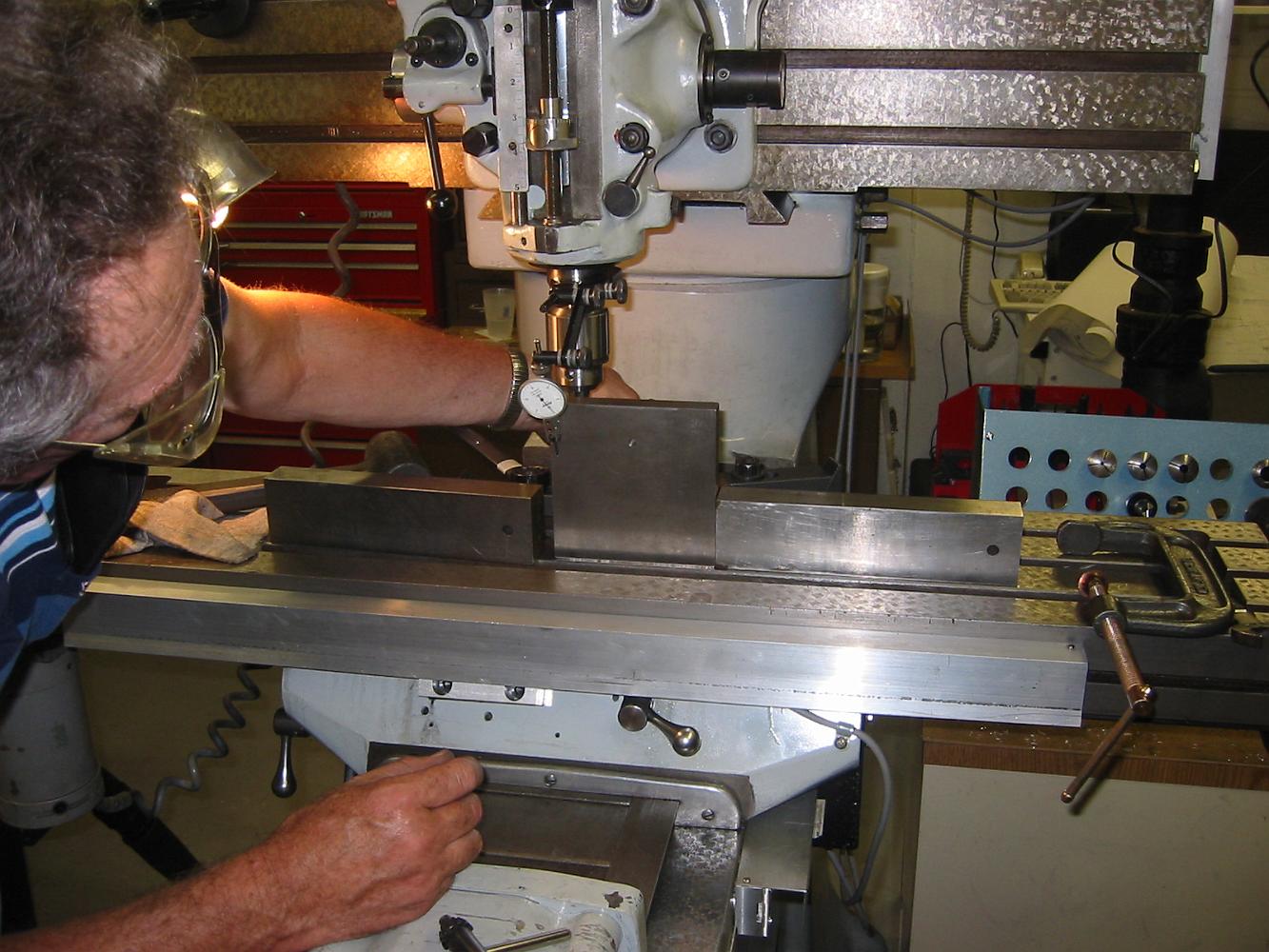
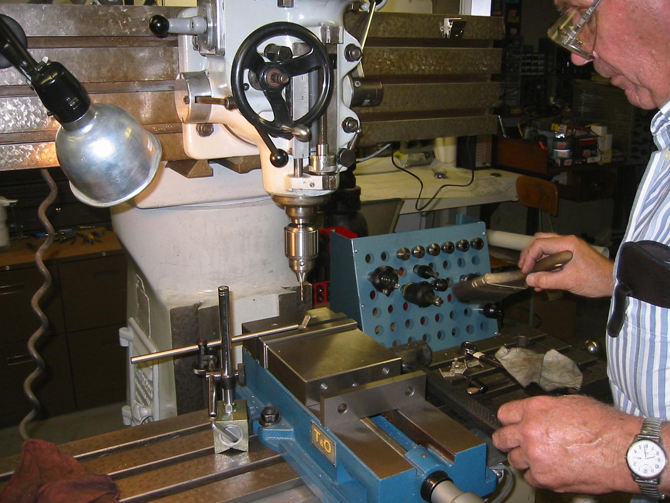
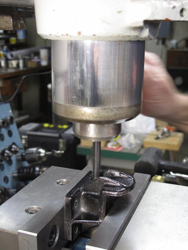
28-Feb-07 Boring the spring pockets. The vacuum nozzle pulls the chips out of the blind pocket to keep the hole clear during the boring step.
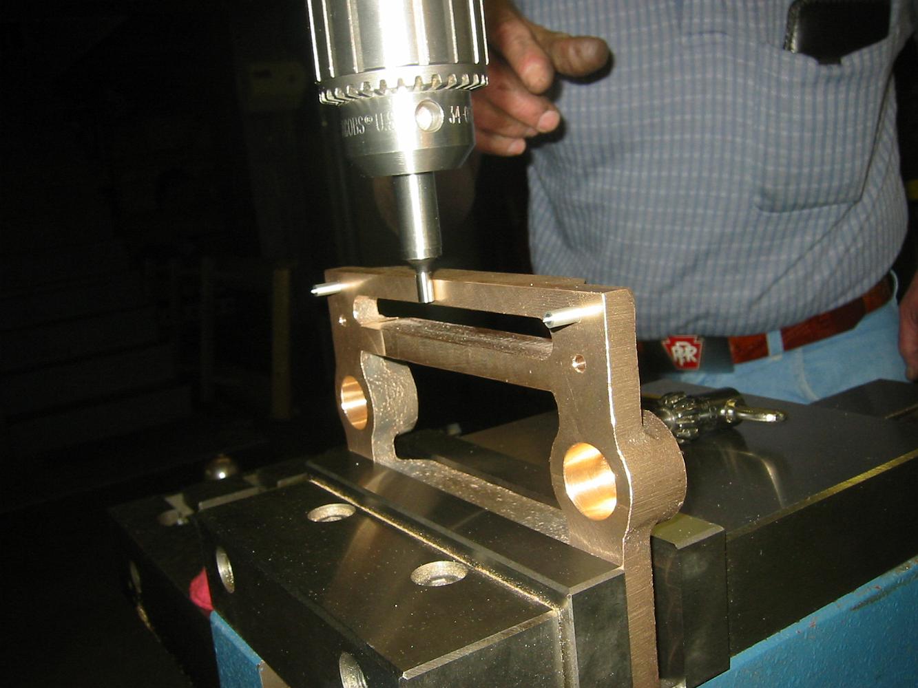
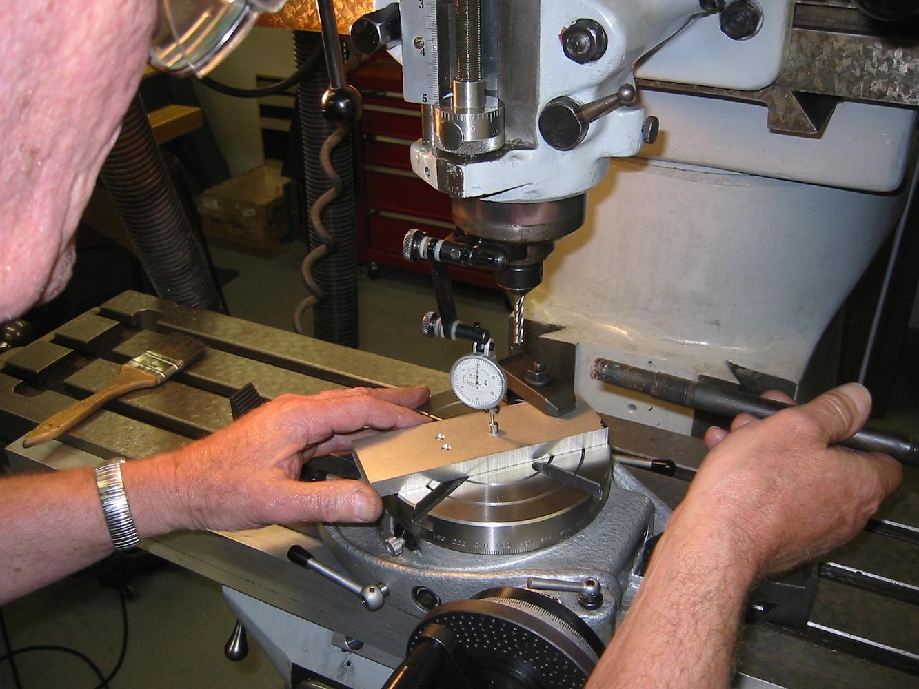
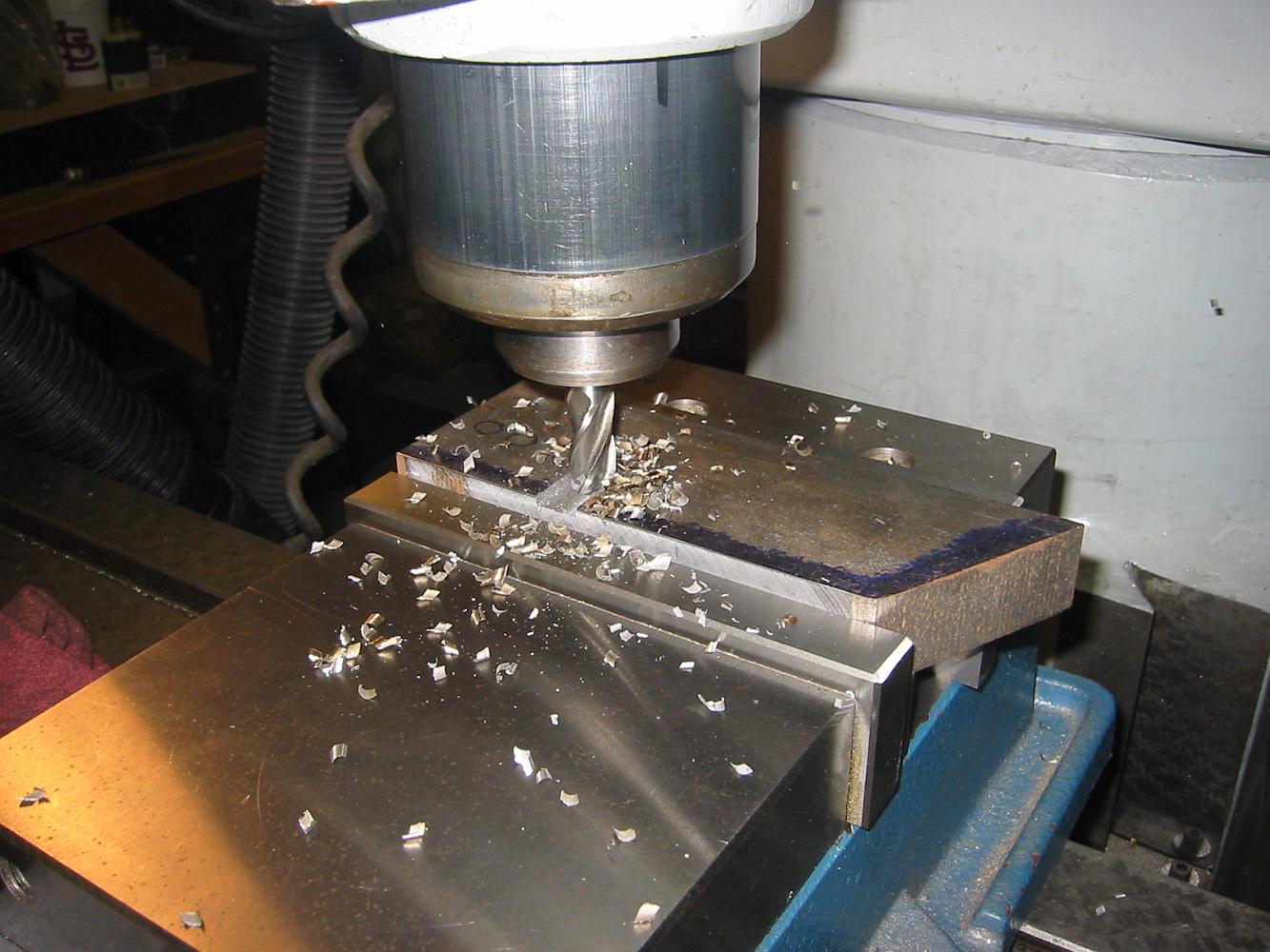
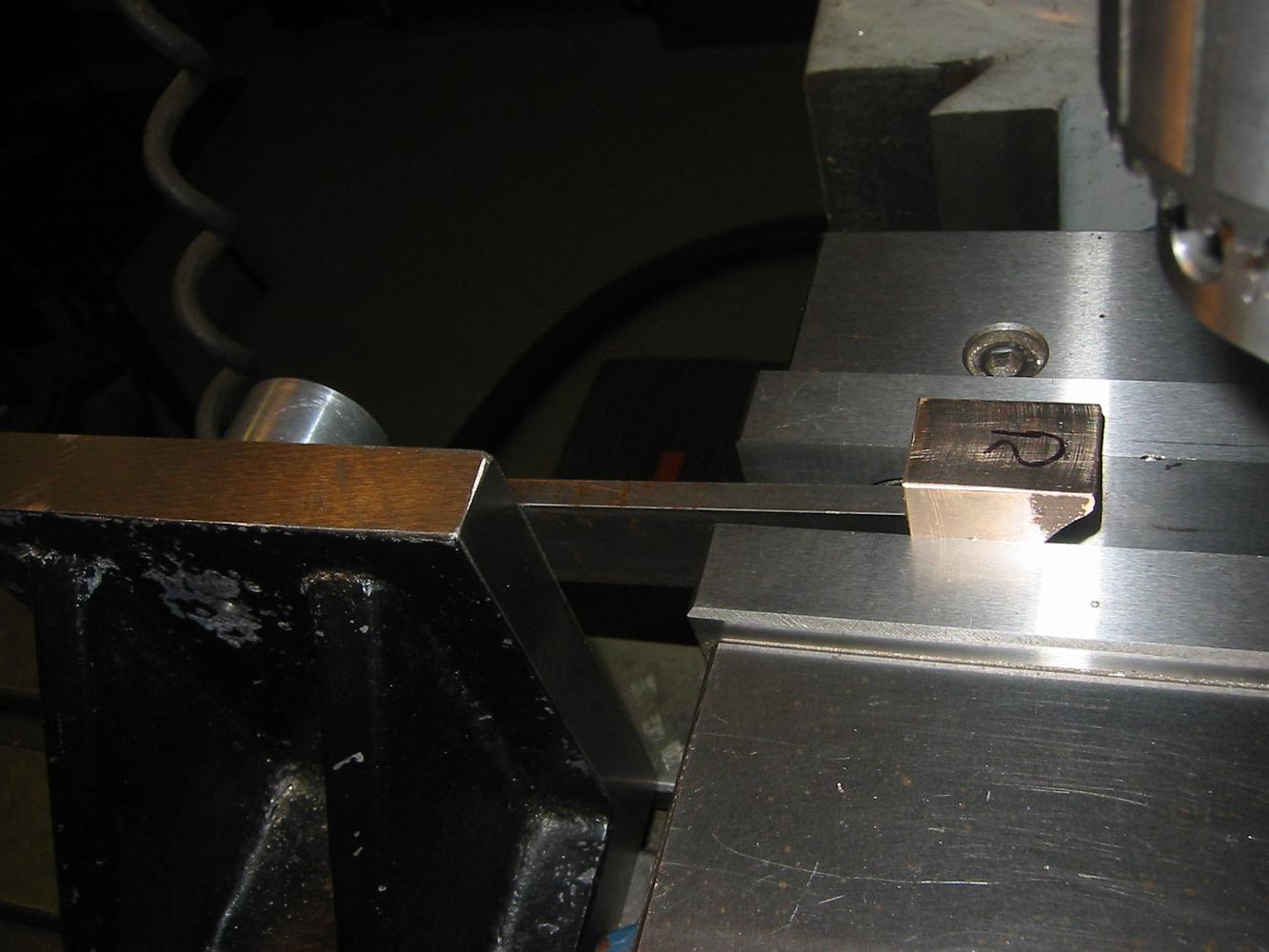
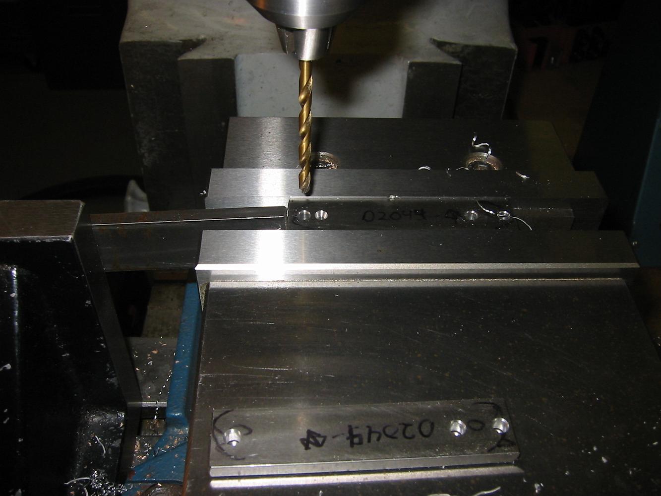
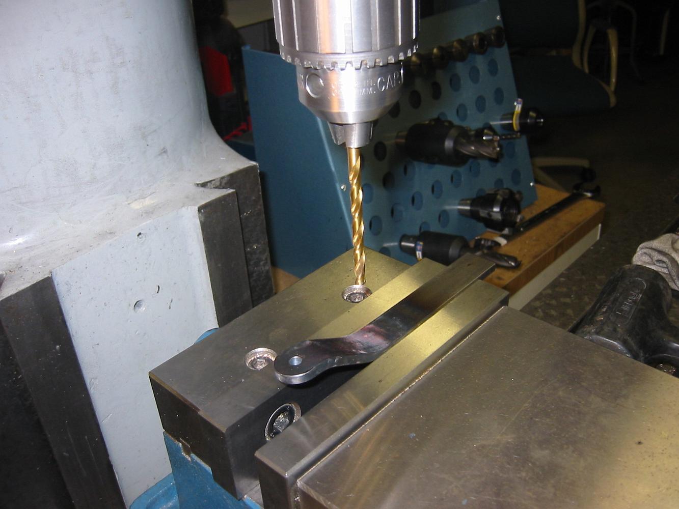
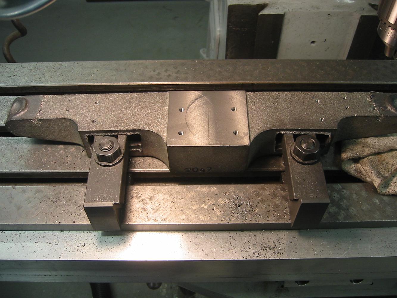
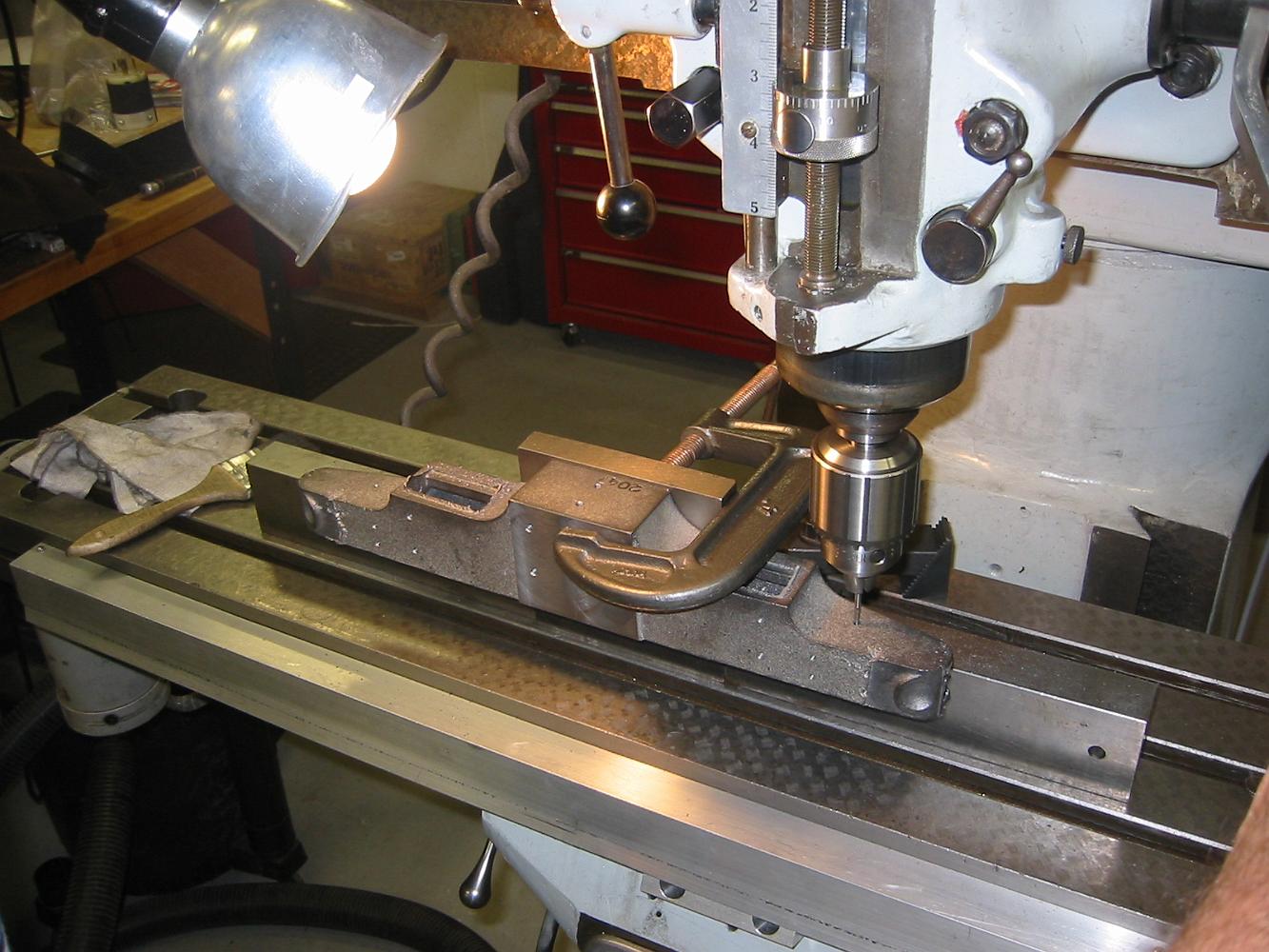
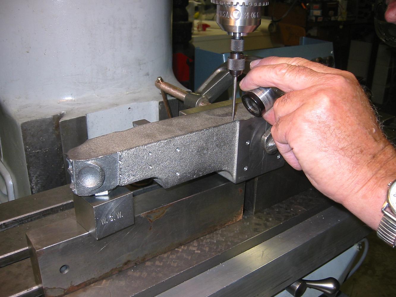
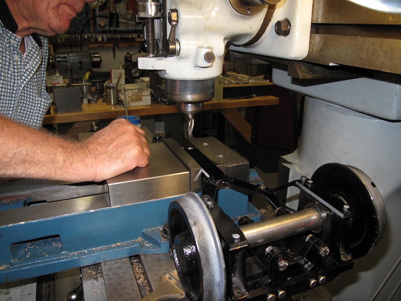
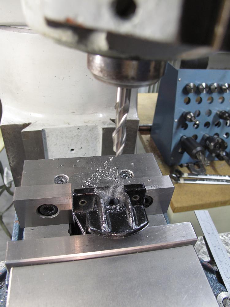
28-Feb-07 Using pins to locate the pilot truck frame so we can drill the holes in the sides.
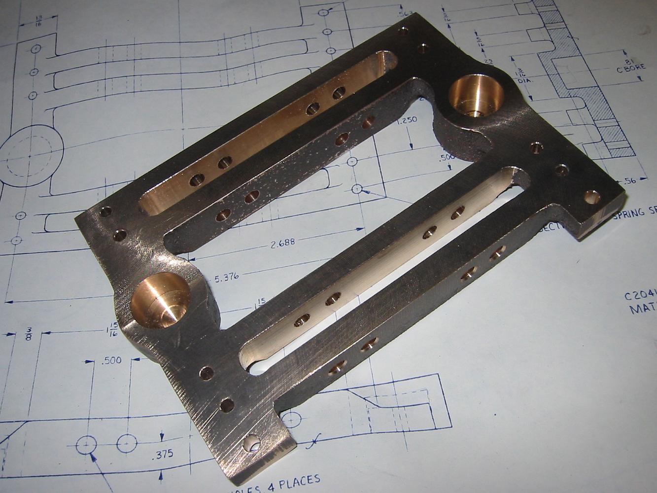
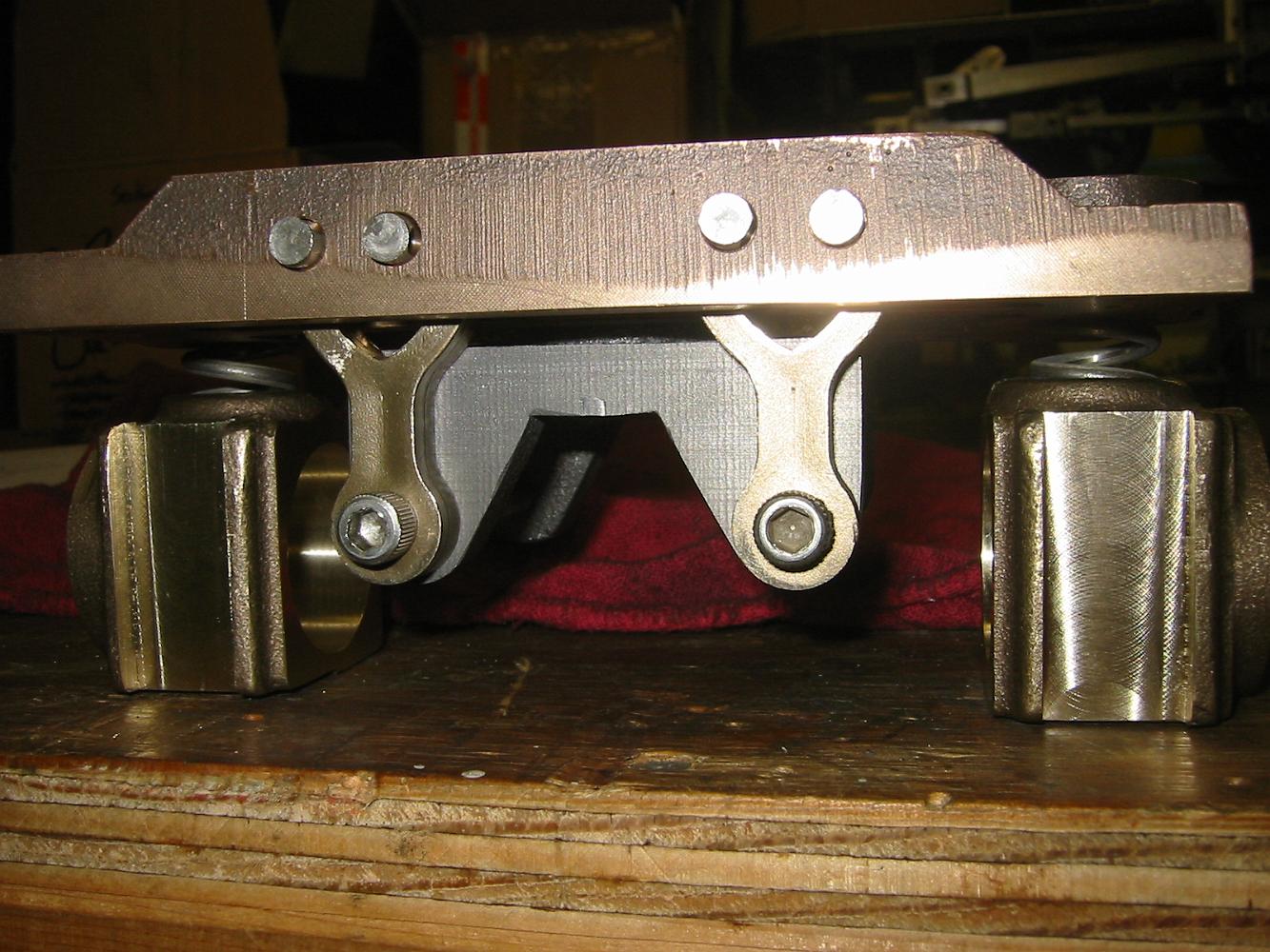
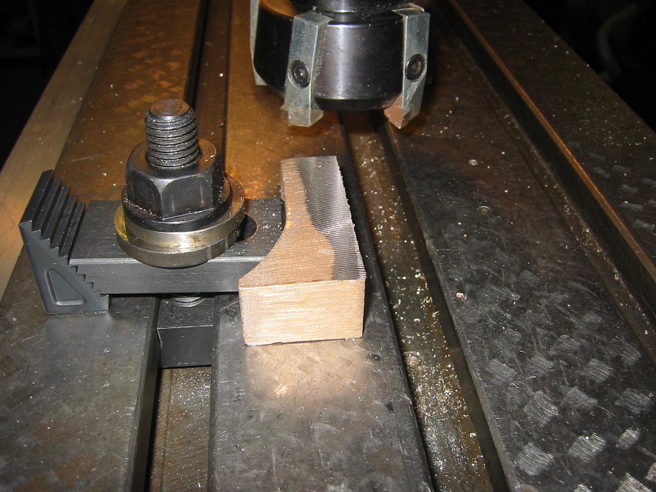
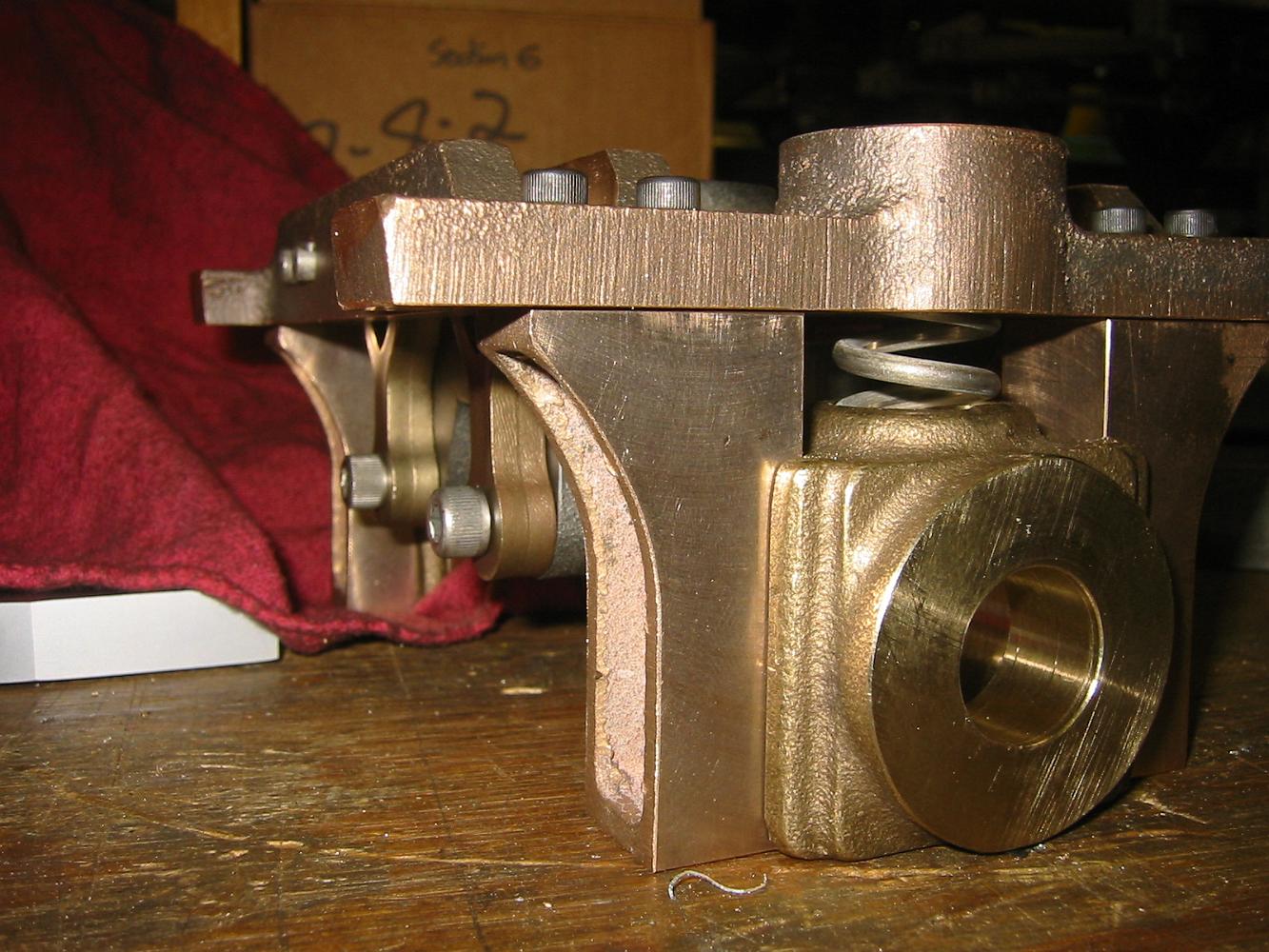
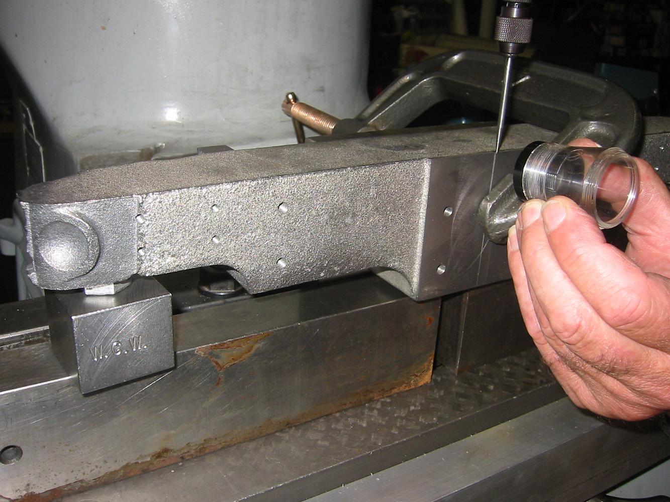
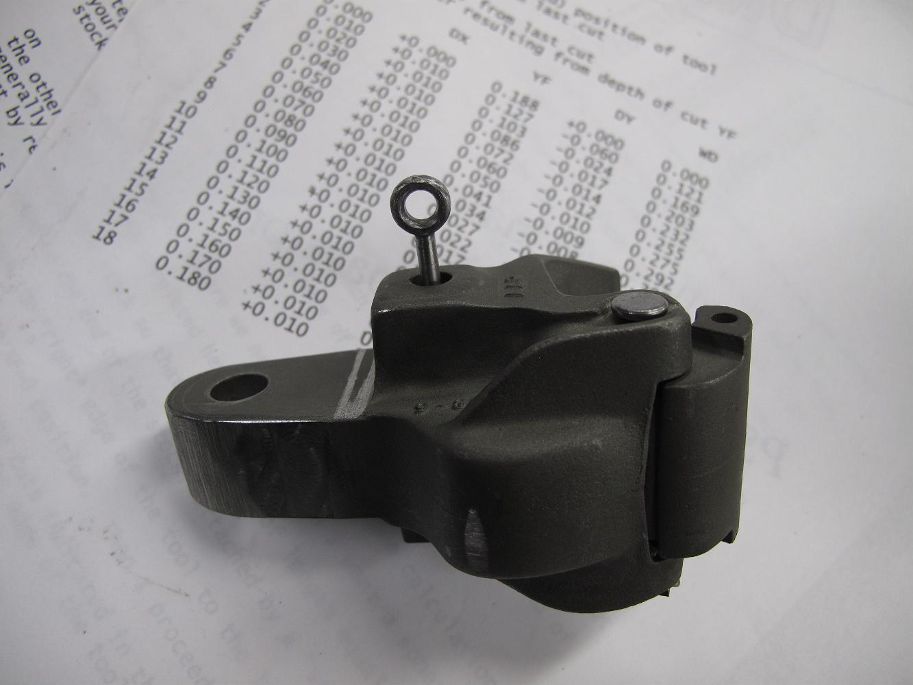
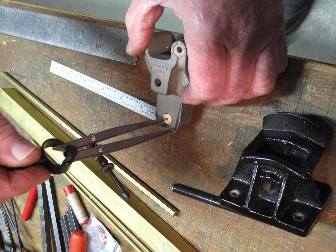
28-Feb-07 The finished pilot truck frame.
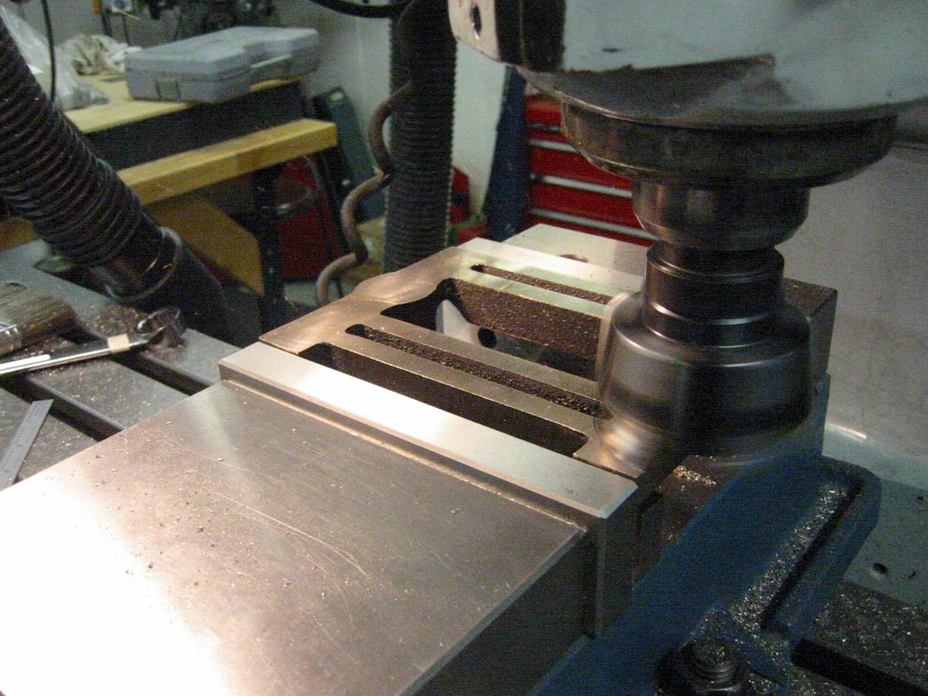
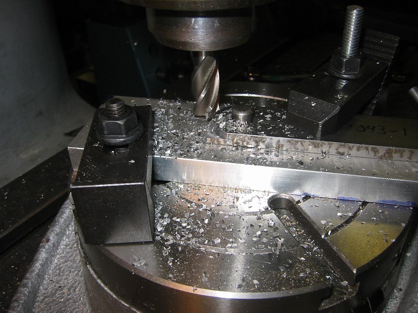
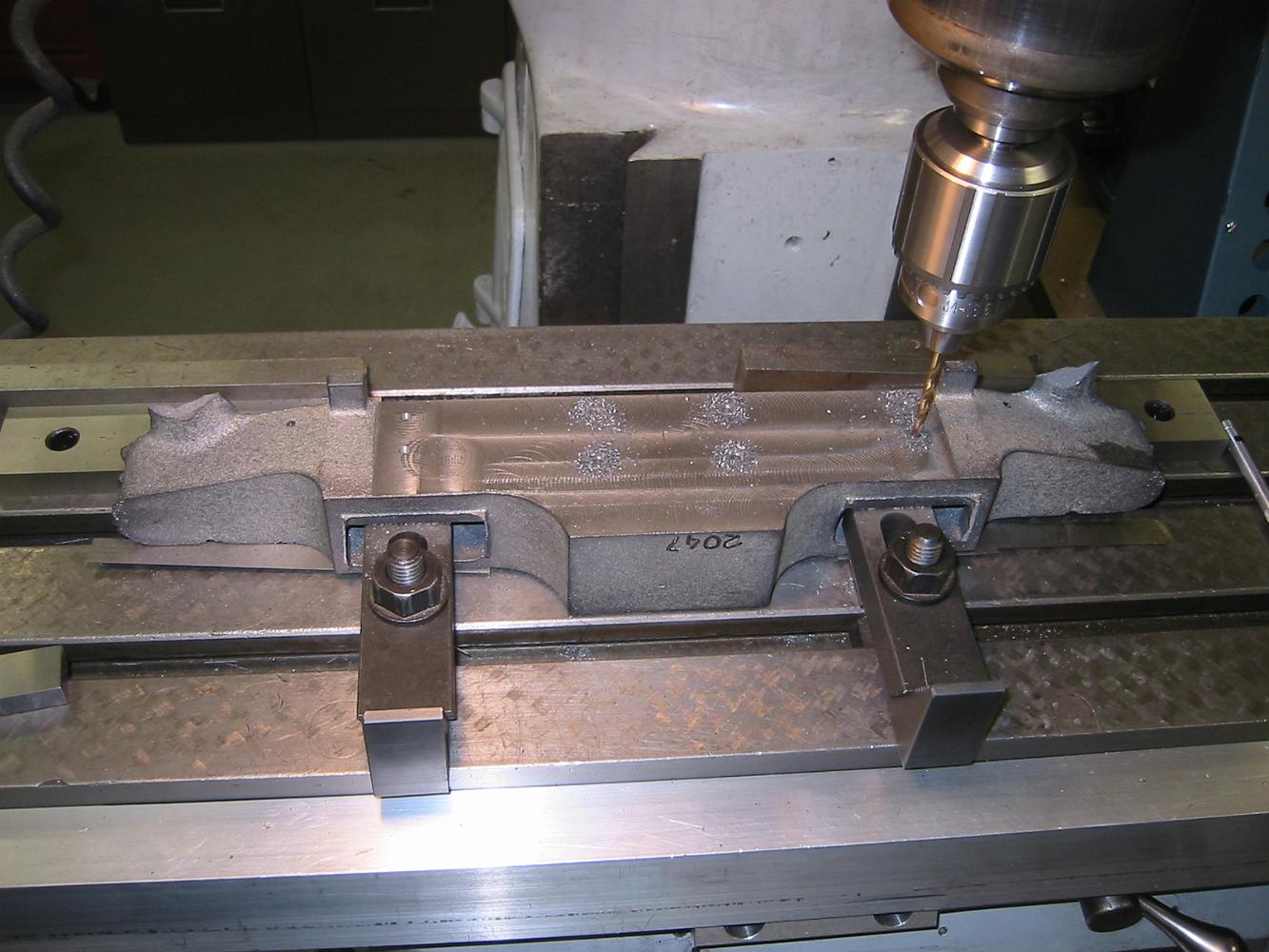
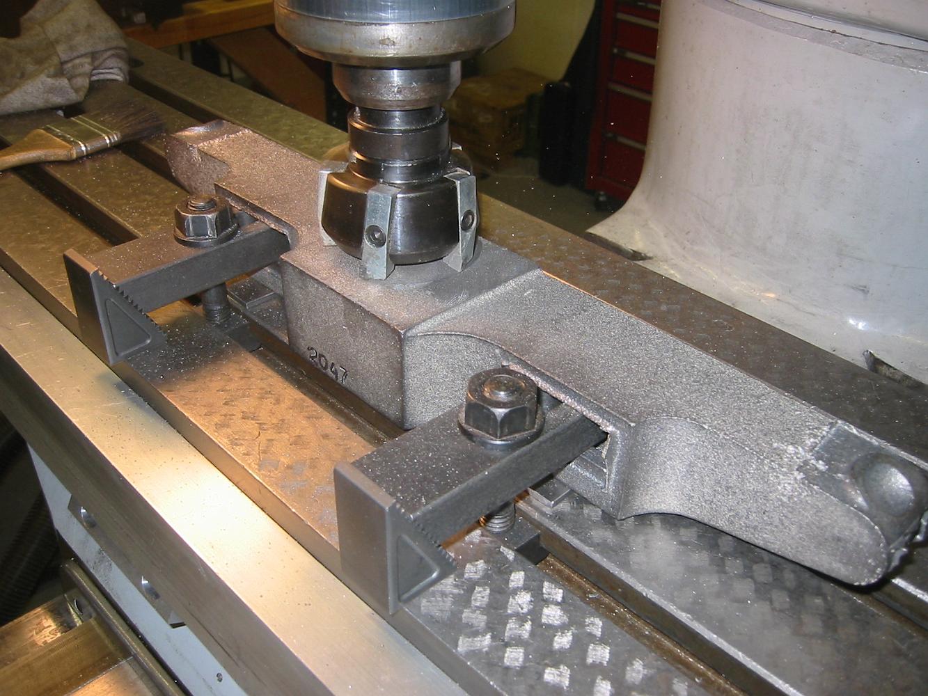
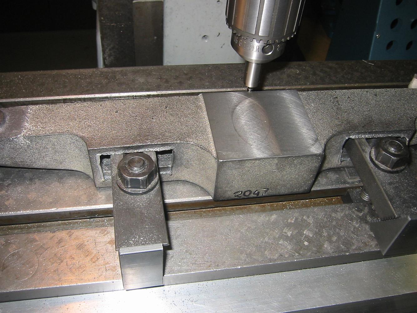
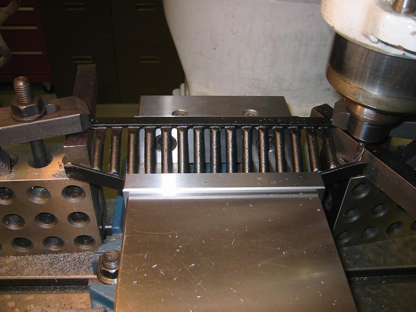
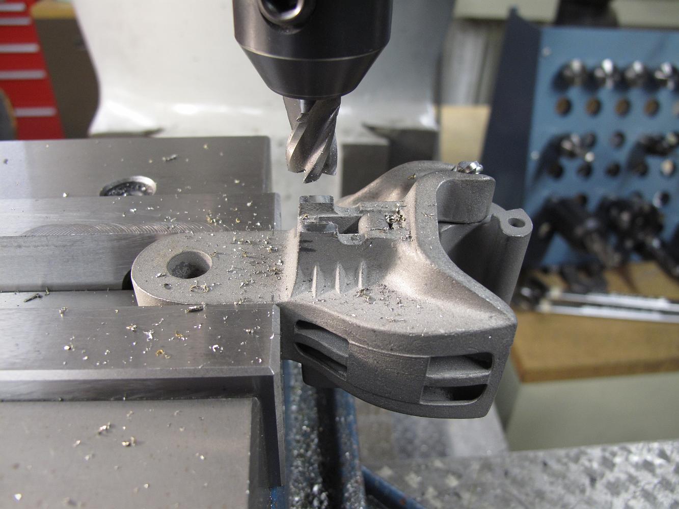
21-Feb-07 Fly cutting the pilot truck frame.
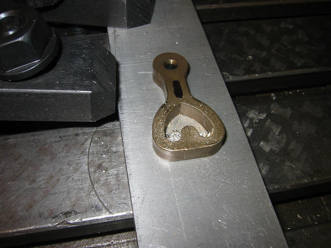
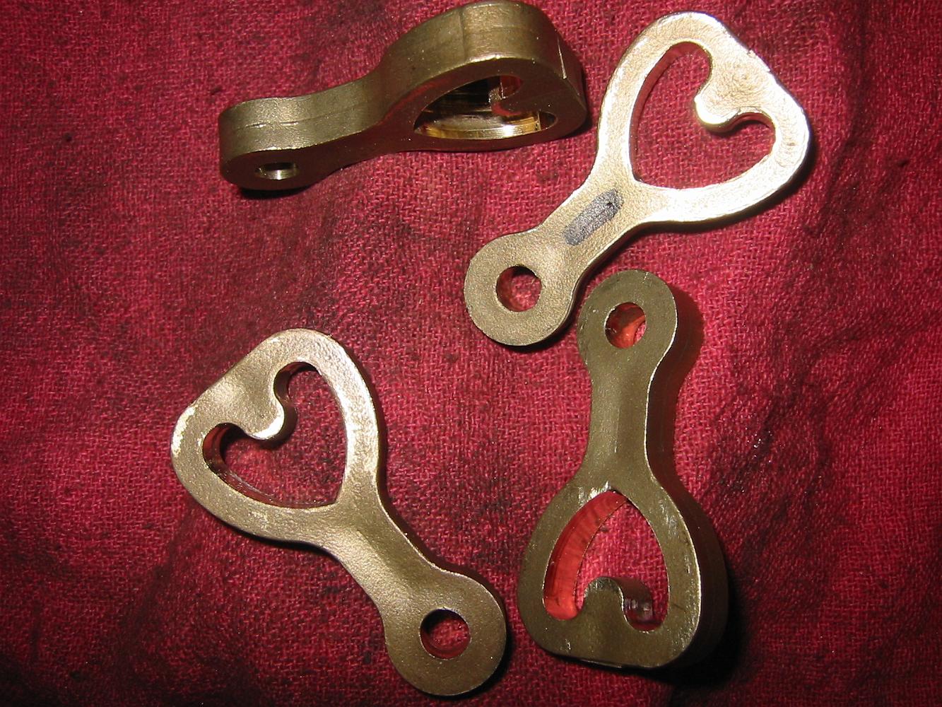
21-Feb-07 We start machining the heart rocker for the pilot trucks. Yeah!
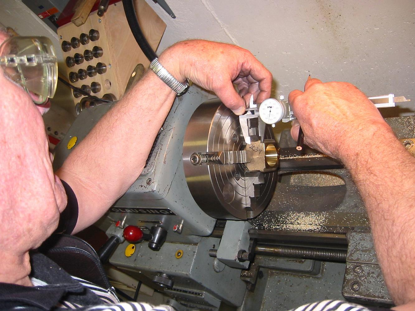
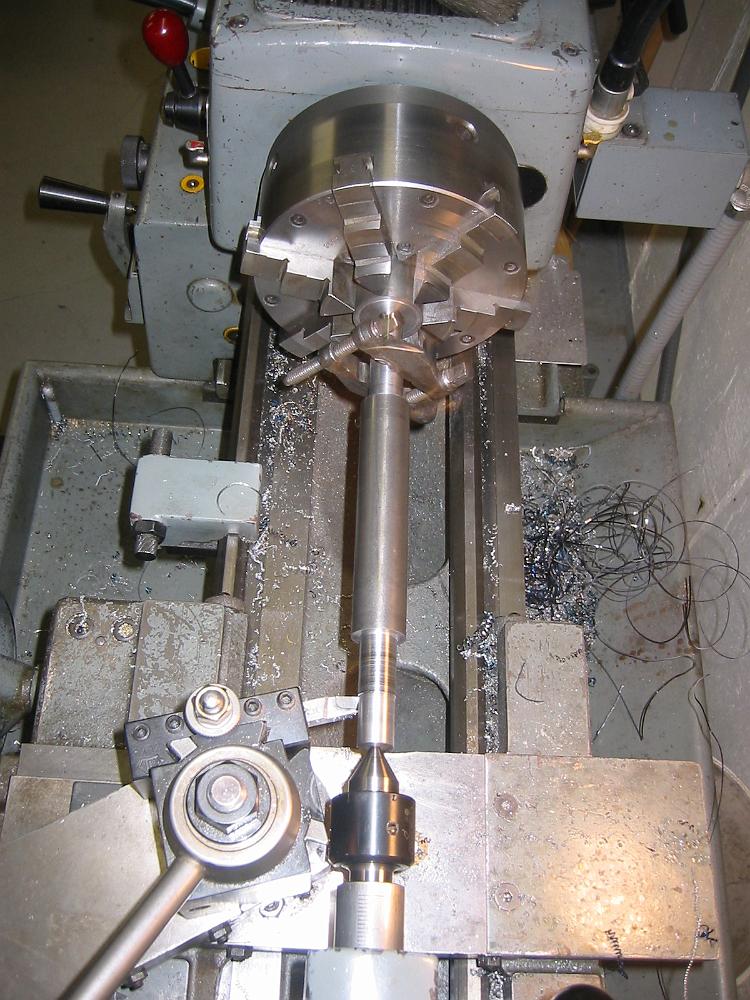
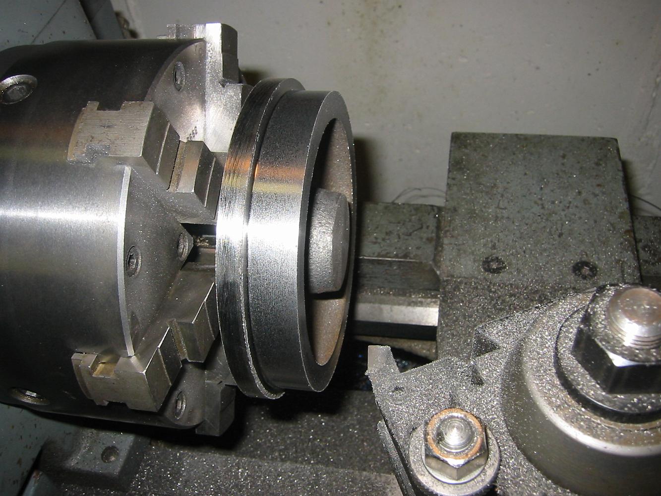
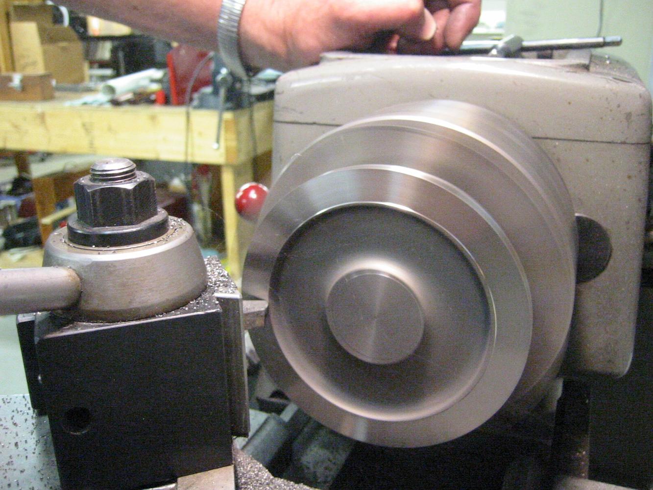
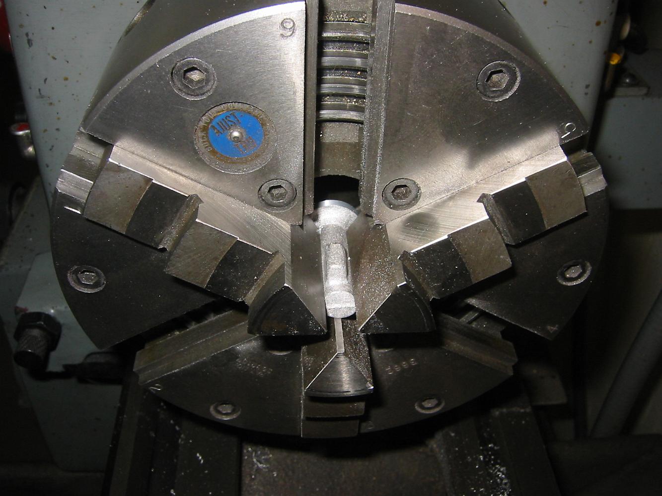
11-Apr-07 Action shot--the axle box has been turned around and tapped square against the chuck face to face the wheel side.
How much do we have to take off? A check with the depth mike from the axle face to the chuck face will tell.
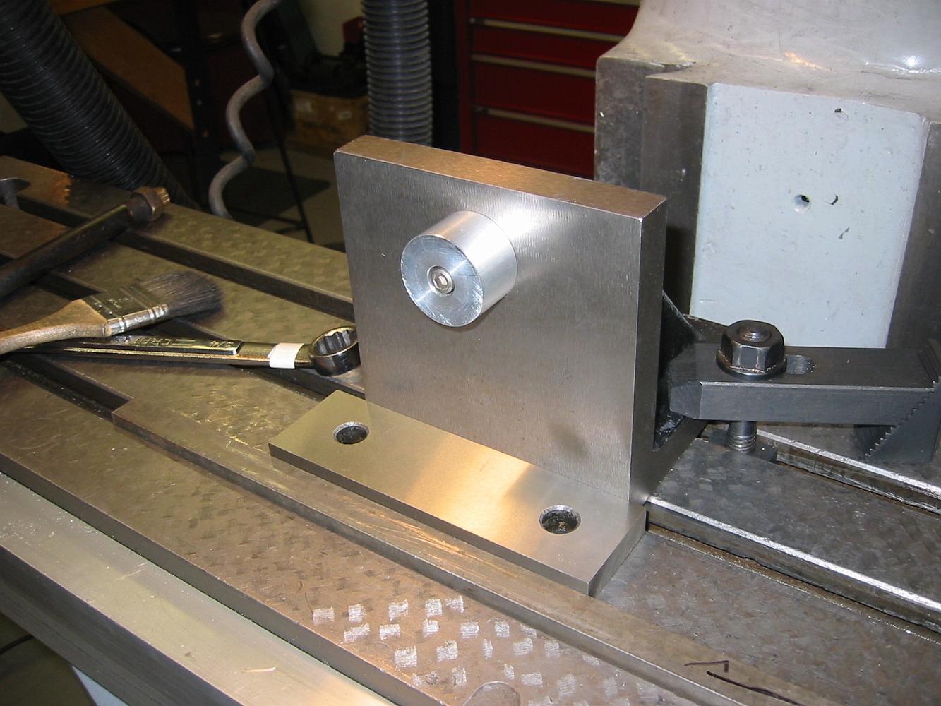
11-Apr-07 Our old friends, the angle plate and aluminum plug are once again reunited. This aluminum plug started out pretty big for the main axle boxes, was…
11-Apr-07 Familiar milling operation, cutting the guide channel in the axle box. Turning the box over to mill the other side, we rotate it on the plug to…
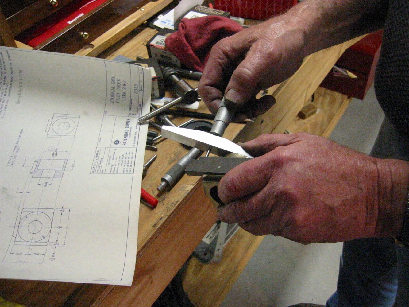
Is the front of the slot set back the proper distance? Putting an adjustable parallel in the slot and using the depth mic will tell.
4-Apr-07 Rough turning the outside of the Swing Bolster.
4-Apr-07 The finished Swing Bolster
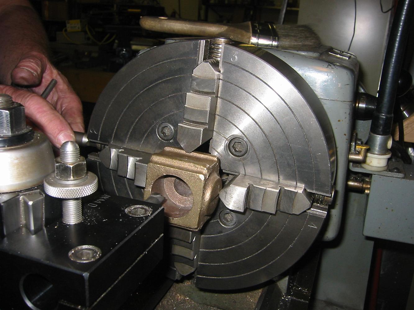
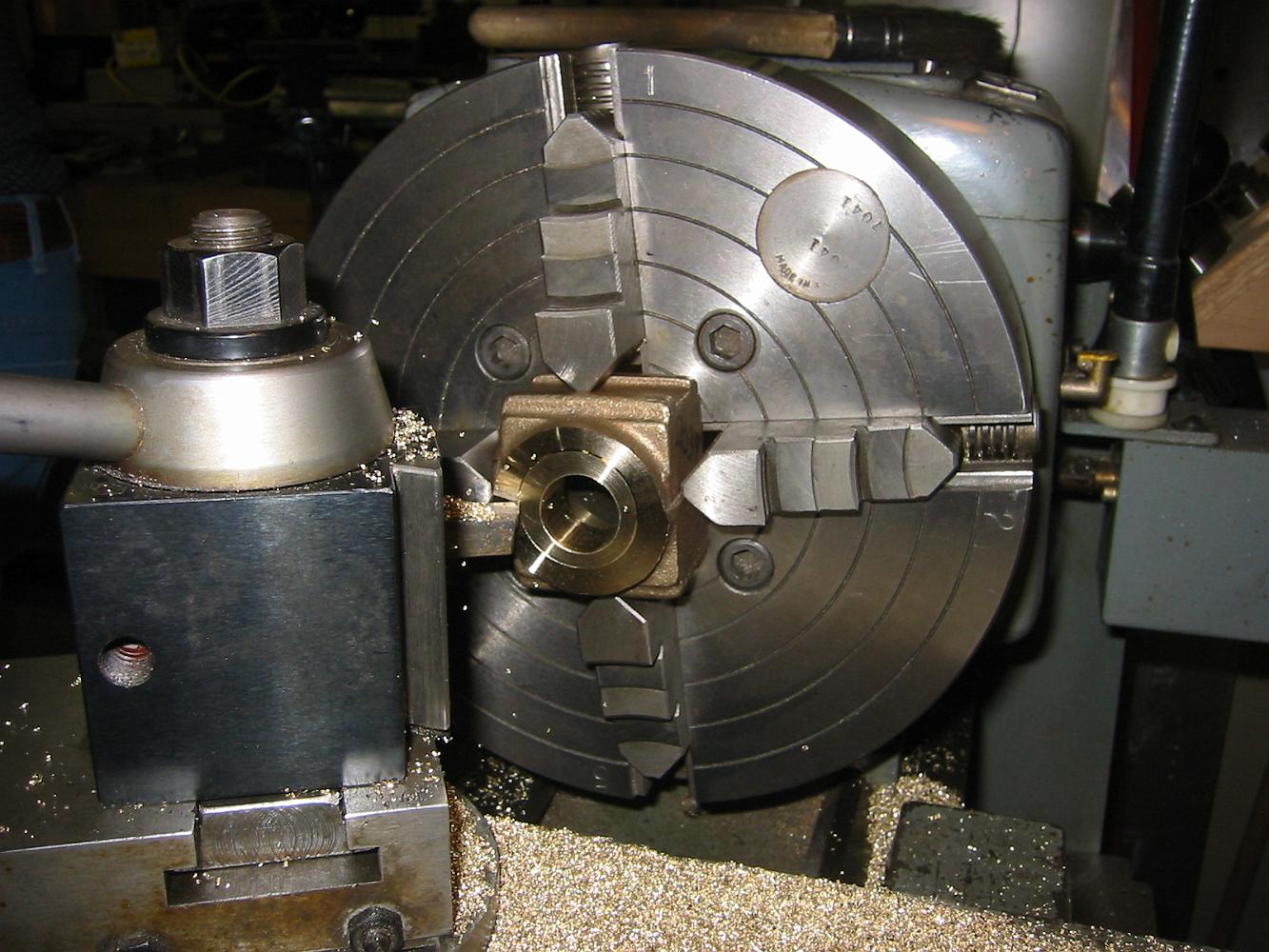
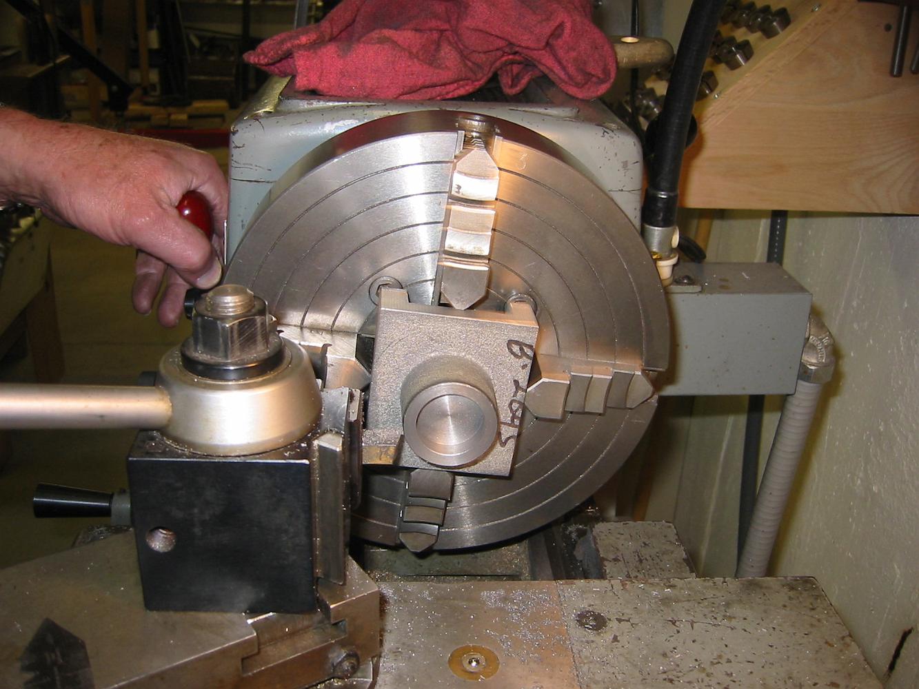
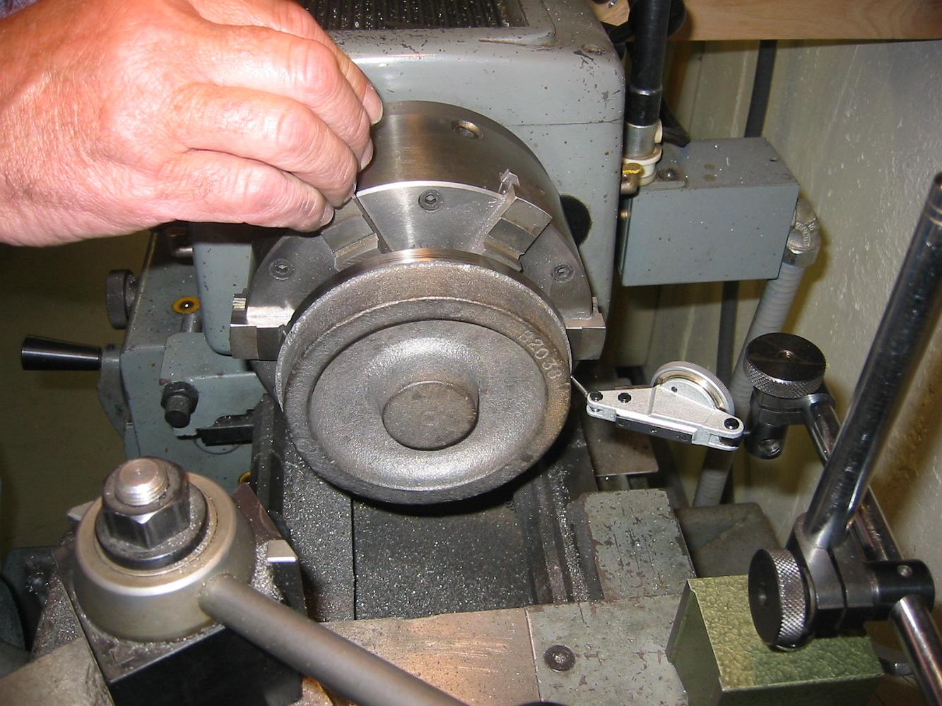
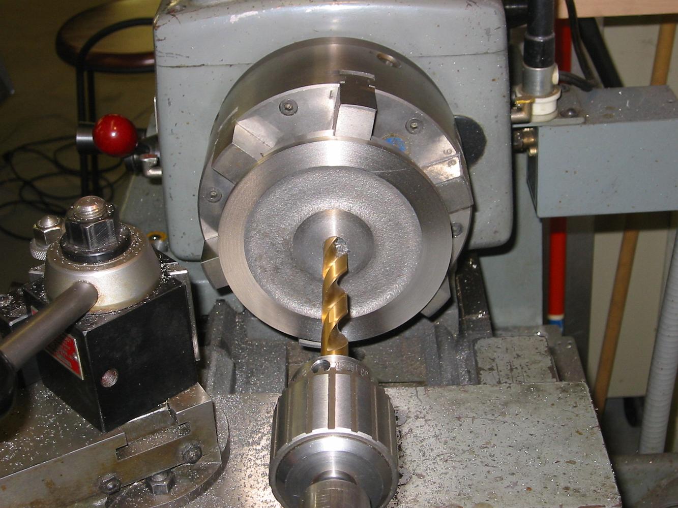
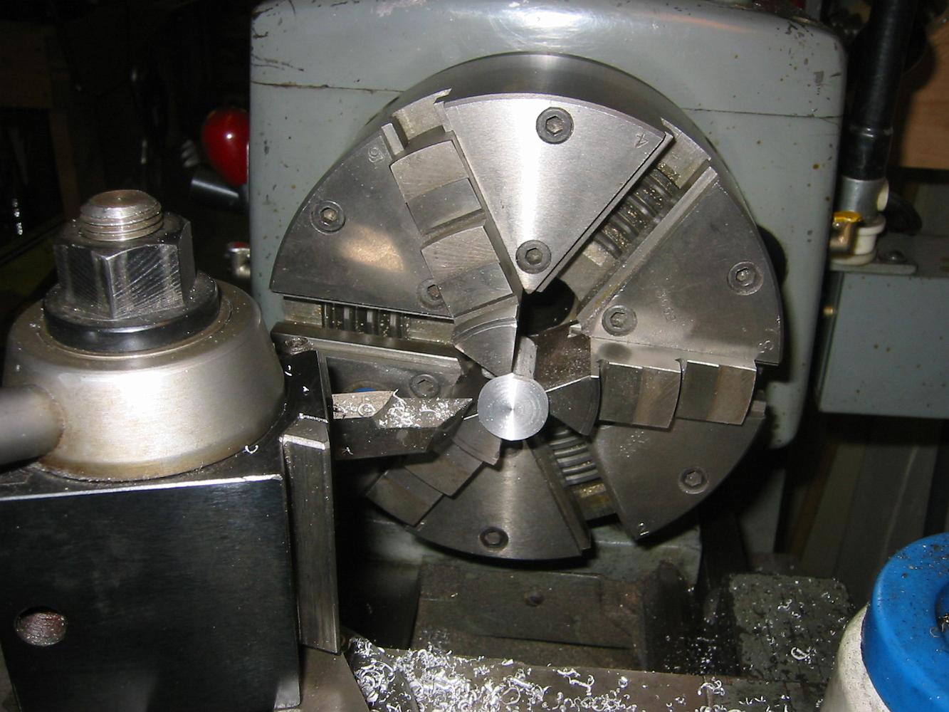
4-Apr-07 By now, this is almost a familiar setup. The front pilot axle box is chucked up in the 4-jaw chuck, centered by eye, and rough bored.
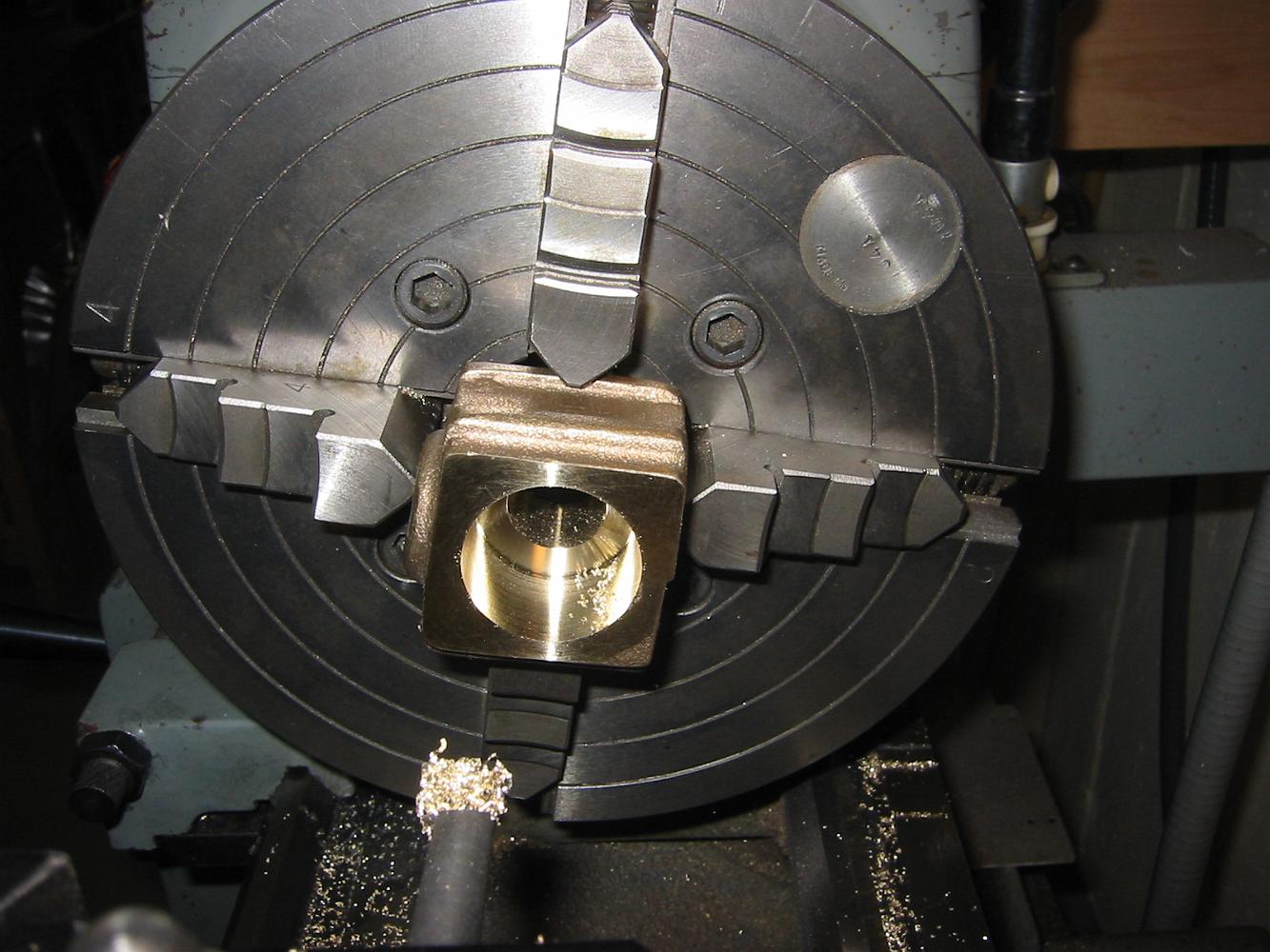
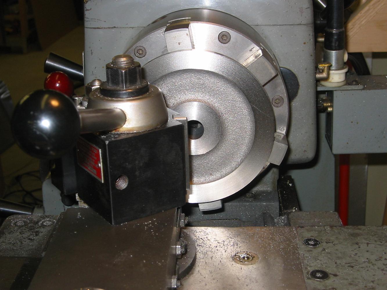
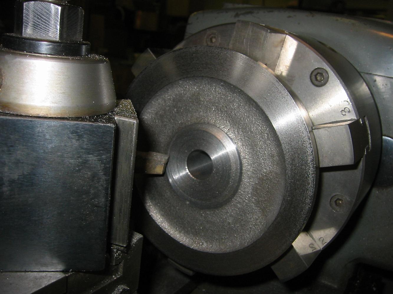
The boring operation complete, the axle box back is faced off.
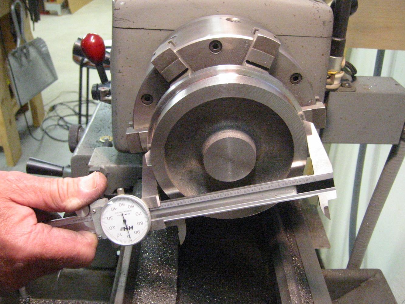
Since the prints reference everything from the back, a quick check to see about how more can be removed from the back while keeping the centerline of the…
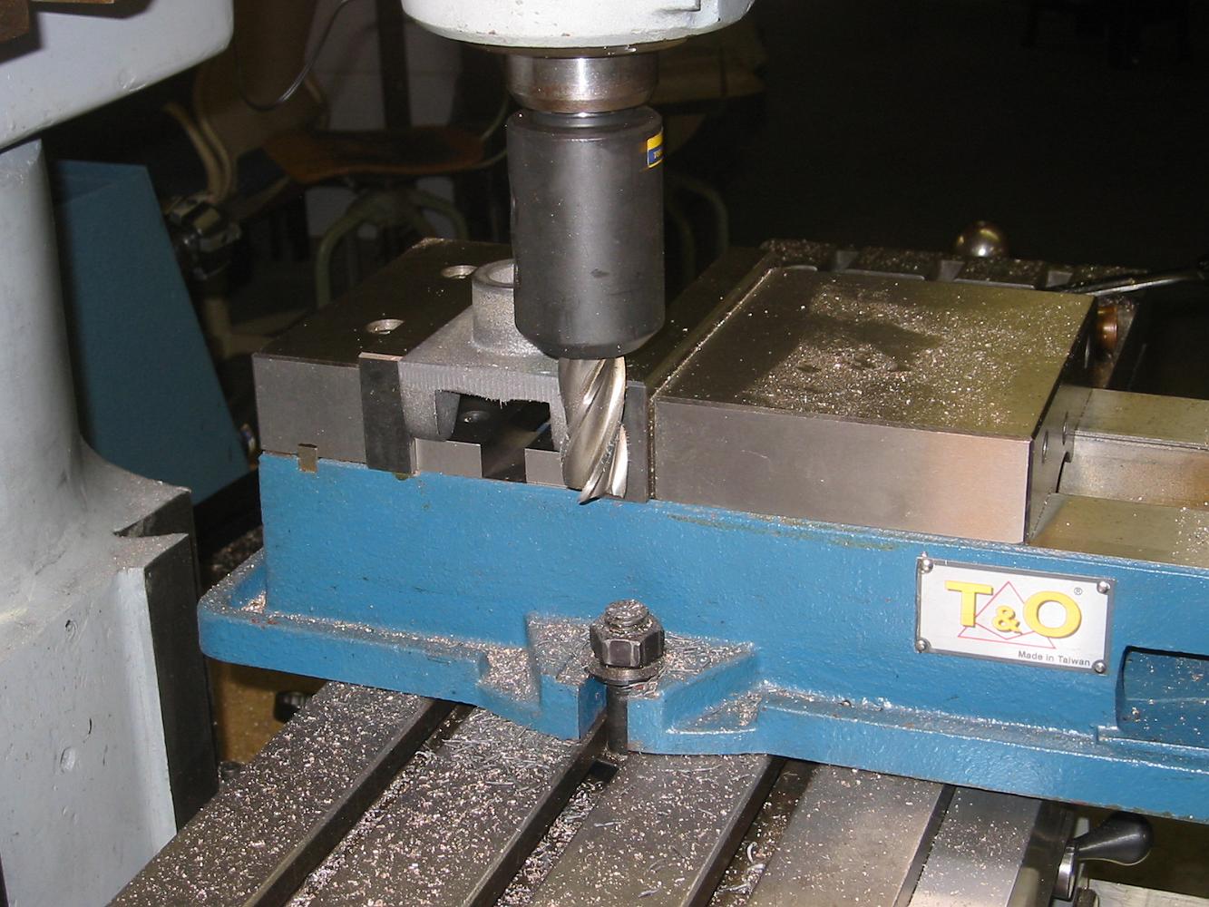
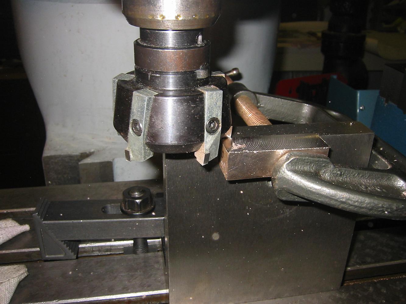
18-Apr-07 Cutting the spring pocket. First we start with the closest large cutter I have (3/4")
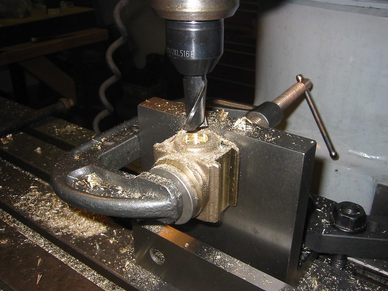
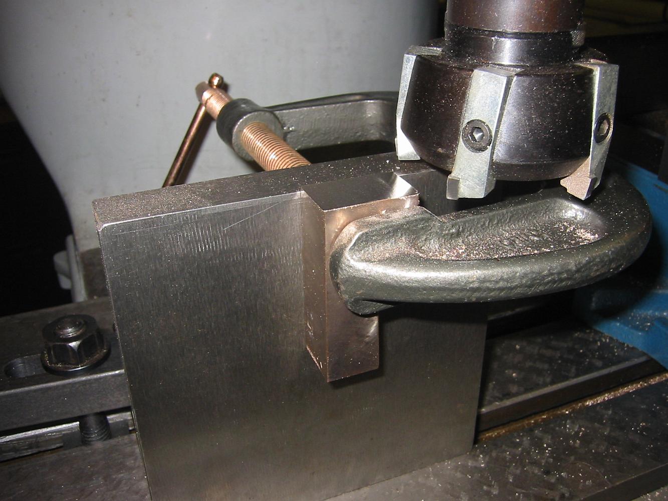
18-Apr-07 Since I did not have the right sized mill to finish the spring pocket, we use a counterbore drill without the pilot.
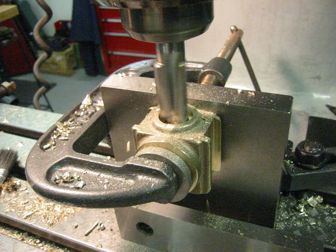
The counterbore in action.
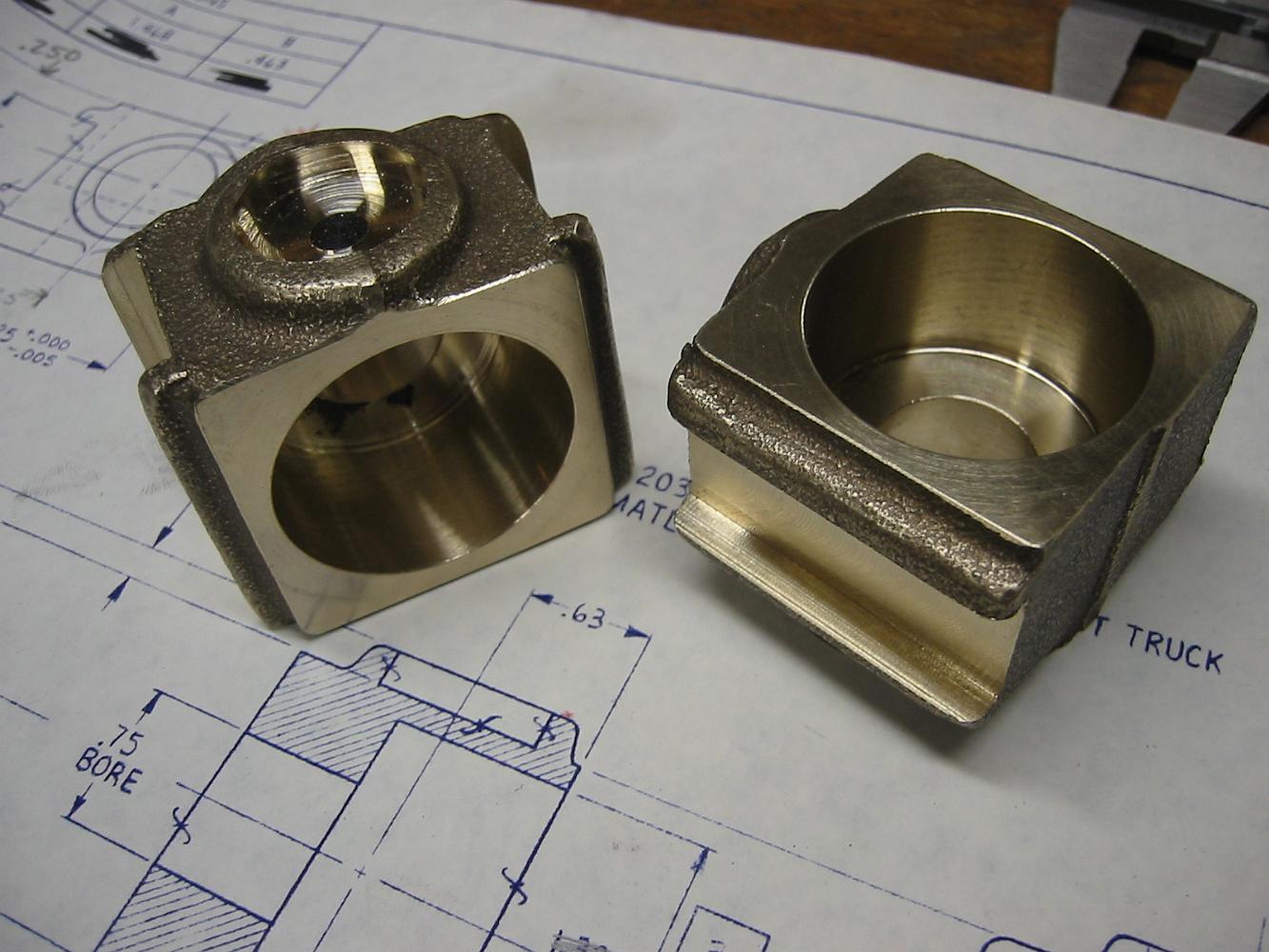
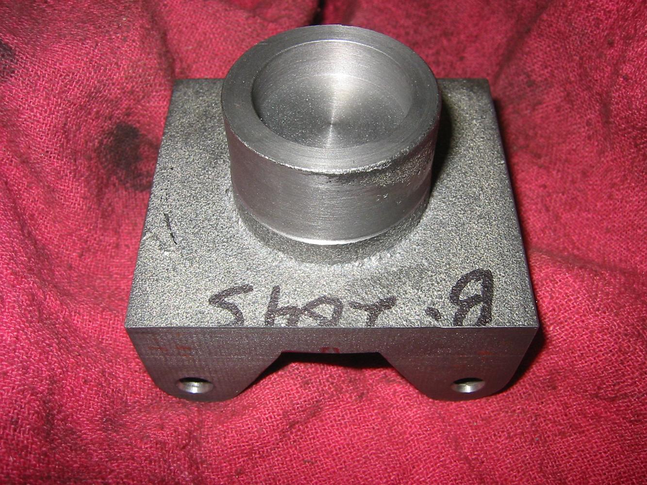
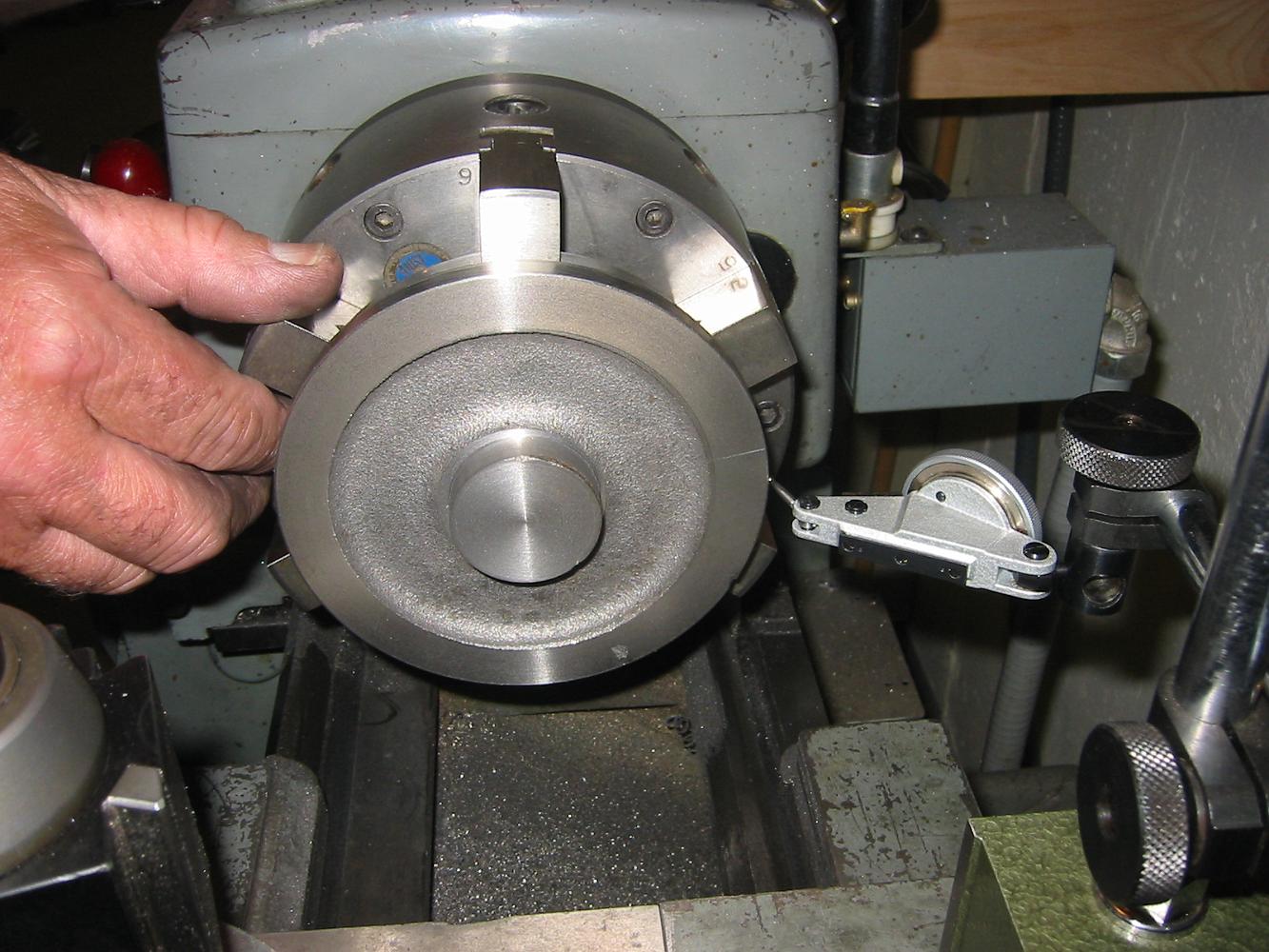
18-Apr-07 The finished pilot truck axle boxes!
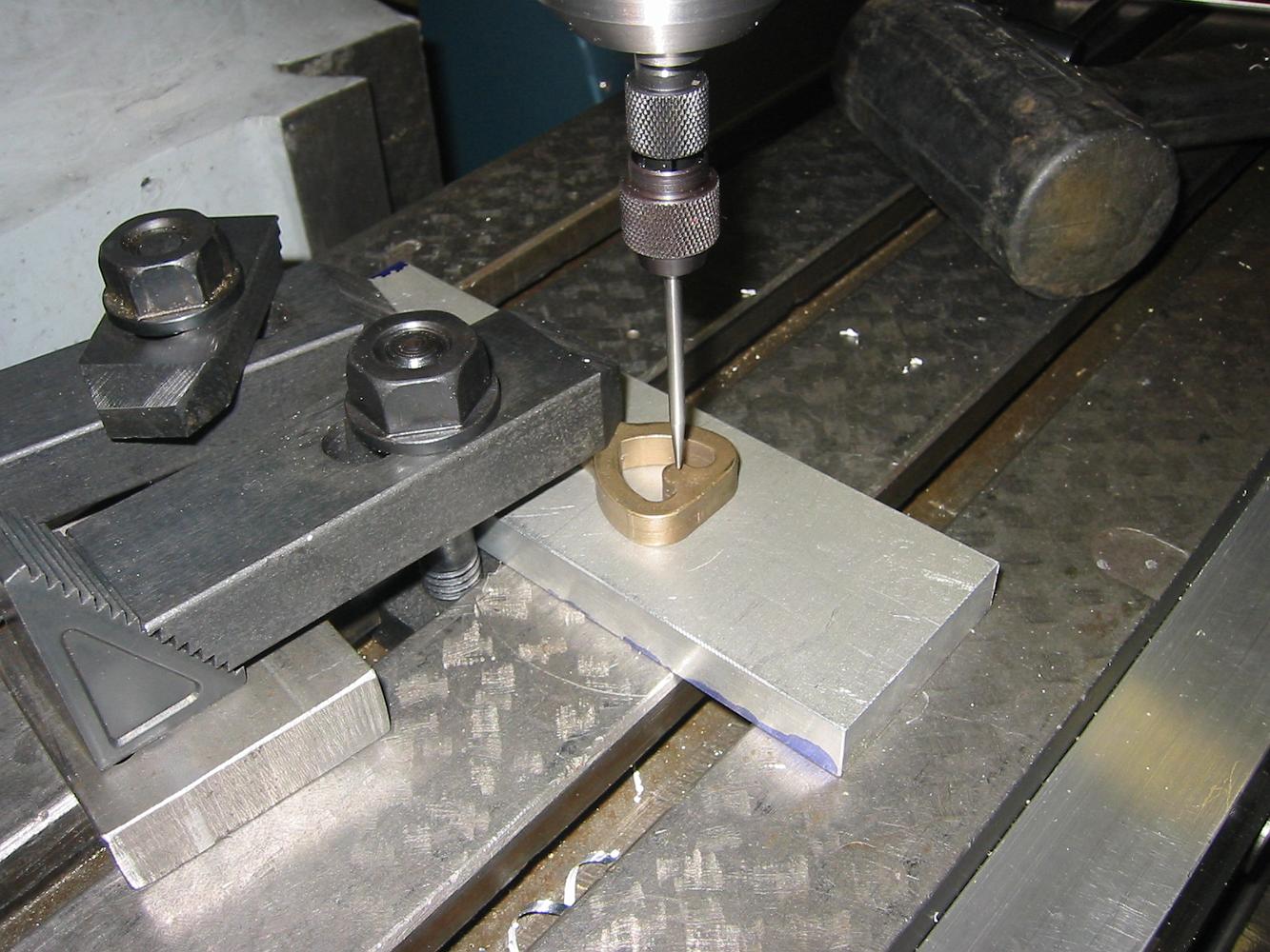
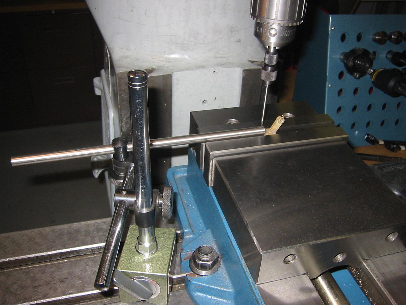
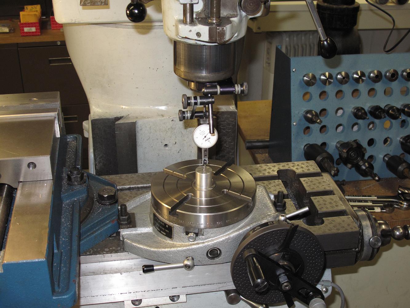
18-Apr-07 Next we start work on the heart links. A piece of aluminum is bolted to the table and a dowel pin in it. The mill head is centered over the pin and…
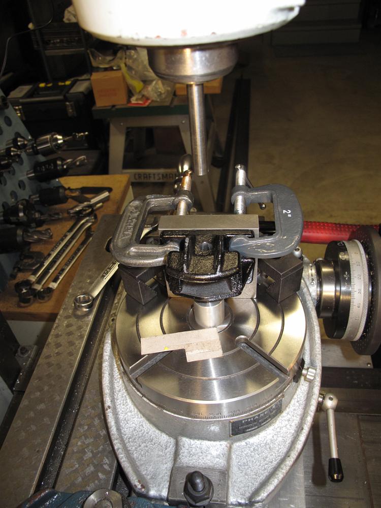
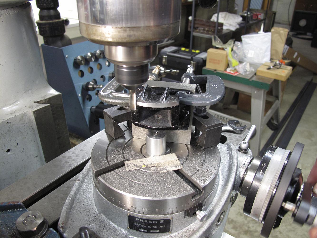
18-Apr-07 To finish the heart links, we have to mill a 5/16" arc inside each side of the link. Out comes the rotary table and the aluminum piece with the dowel…
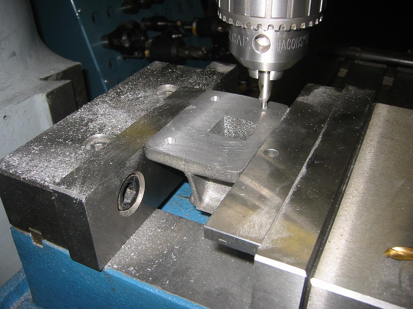
1-May-07 Starting on the Pedestal blocks. We have to machine these castings on 5 out of 6 sides. Step 1: pick a side and machine it.
A quick alignment with the precision square and the top is skimmed until we have a machined surface. The casting does not allow a lot of material to be removed…
A quick way to machine all four blocks to the same size. The every-other orientation insures any angular introduced in the setup is the same for each pair.
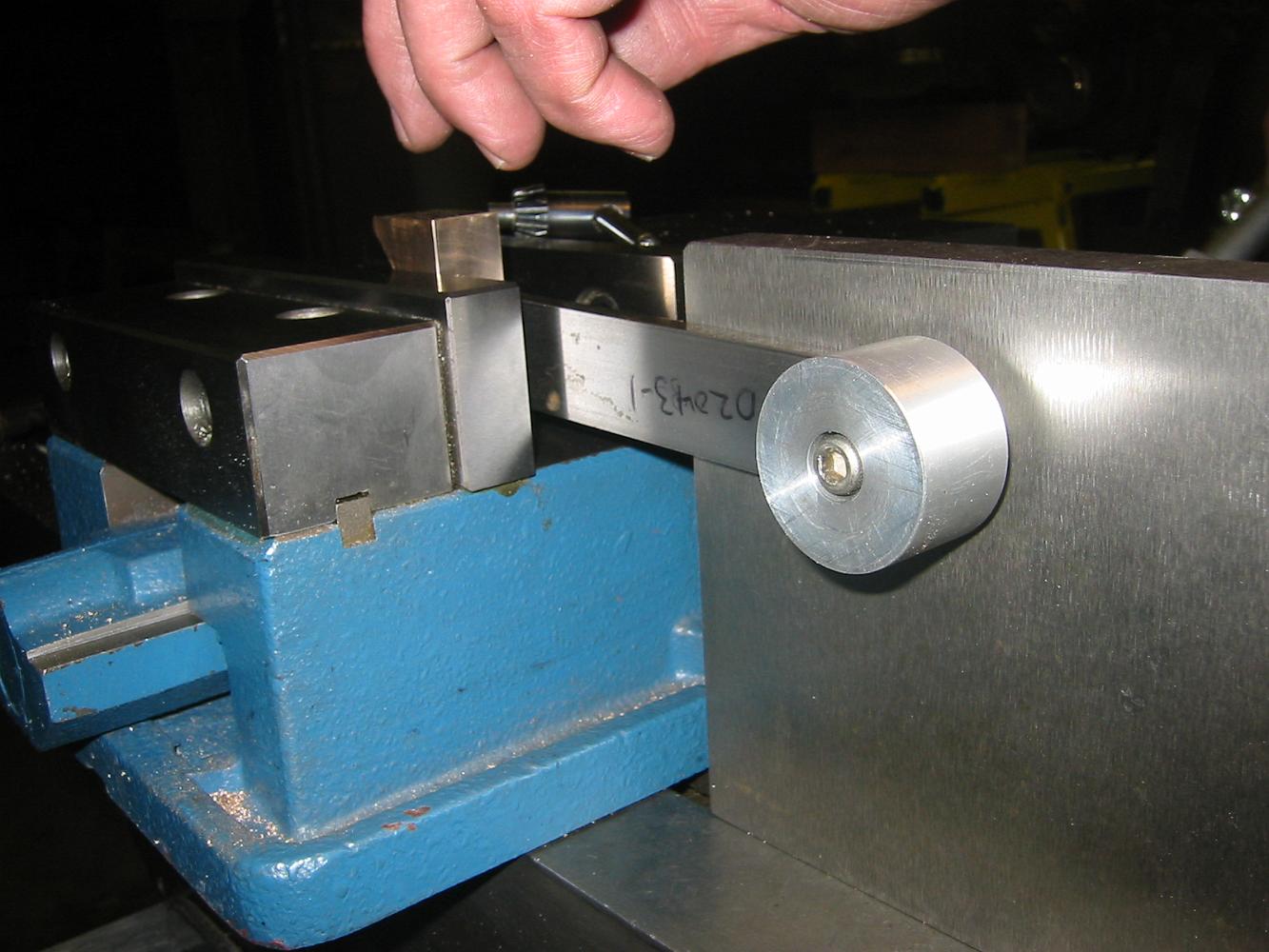
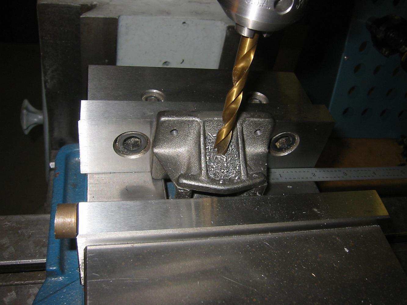
1-May-07 Last set on the pedestal blocks: drill the holes in the top and bottom. Bill sets up a 'vice stop' using the angle plate and a piece of bar stock.
The Vice Stop in use. Between part changes, the setup is not disturbed, so each part can be quickly set into the same position for drilling and tapping.
1-May-06 The finished Pedestal binders bolted to the pilot truck frame. Yea! Hey, that was four parts and one whole print completed in one four hour session.…
16-May-07 Steps to machine the pilot wheels. This is the second chucking. In the first chucking the front of the wheel was held and the back rough turned. Most…
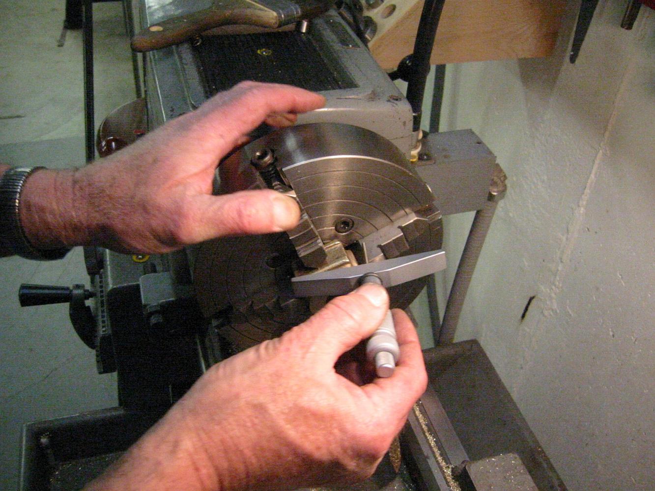
Checking the runout on the second chucking. Since this is a 'adjust-tru' six jaw chuck, we can center the wheel within a couple of thou.
An obscured shot of the boring operation. We tried for a 0.001" undersize to get a press fit. We ended up with 0.0016" and 0.0013", a little more than…
Finish facing the backside. You can see the casting on the back is offset from the front, which is okay because the first chucking setup is the reference and…
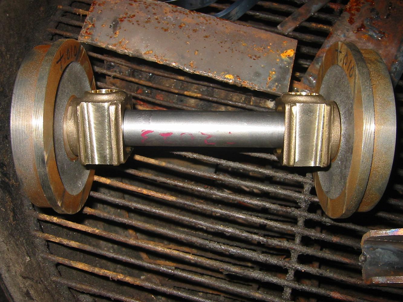
23-May-07 After soaking in a 250 degree oven for a bit, the wheels are pressed on the axle. Here they are cooling down on the weld-r-que.
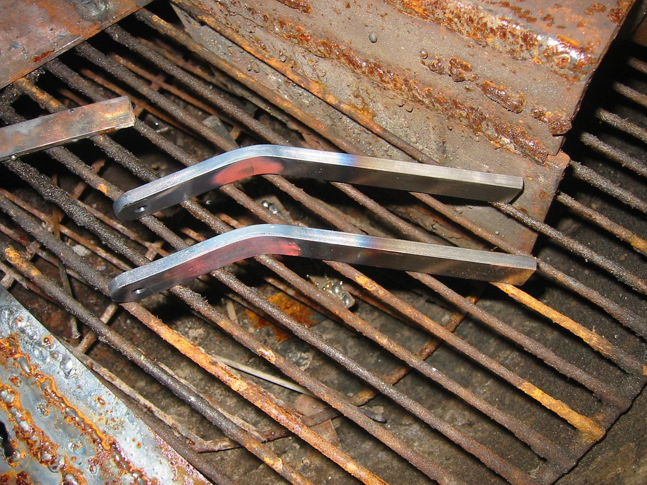
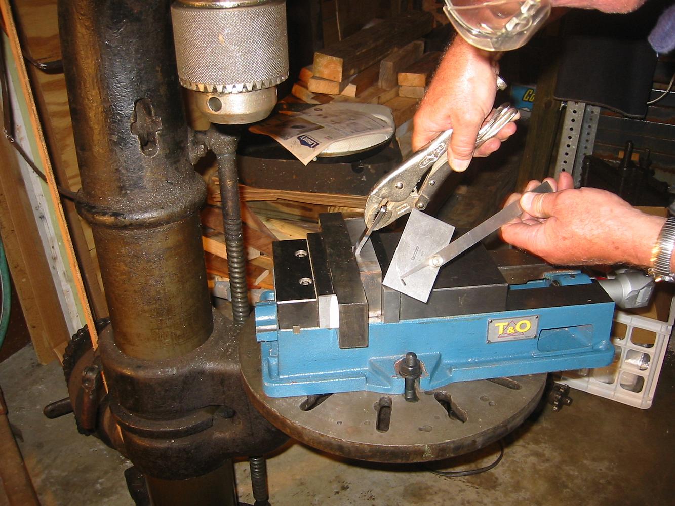
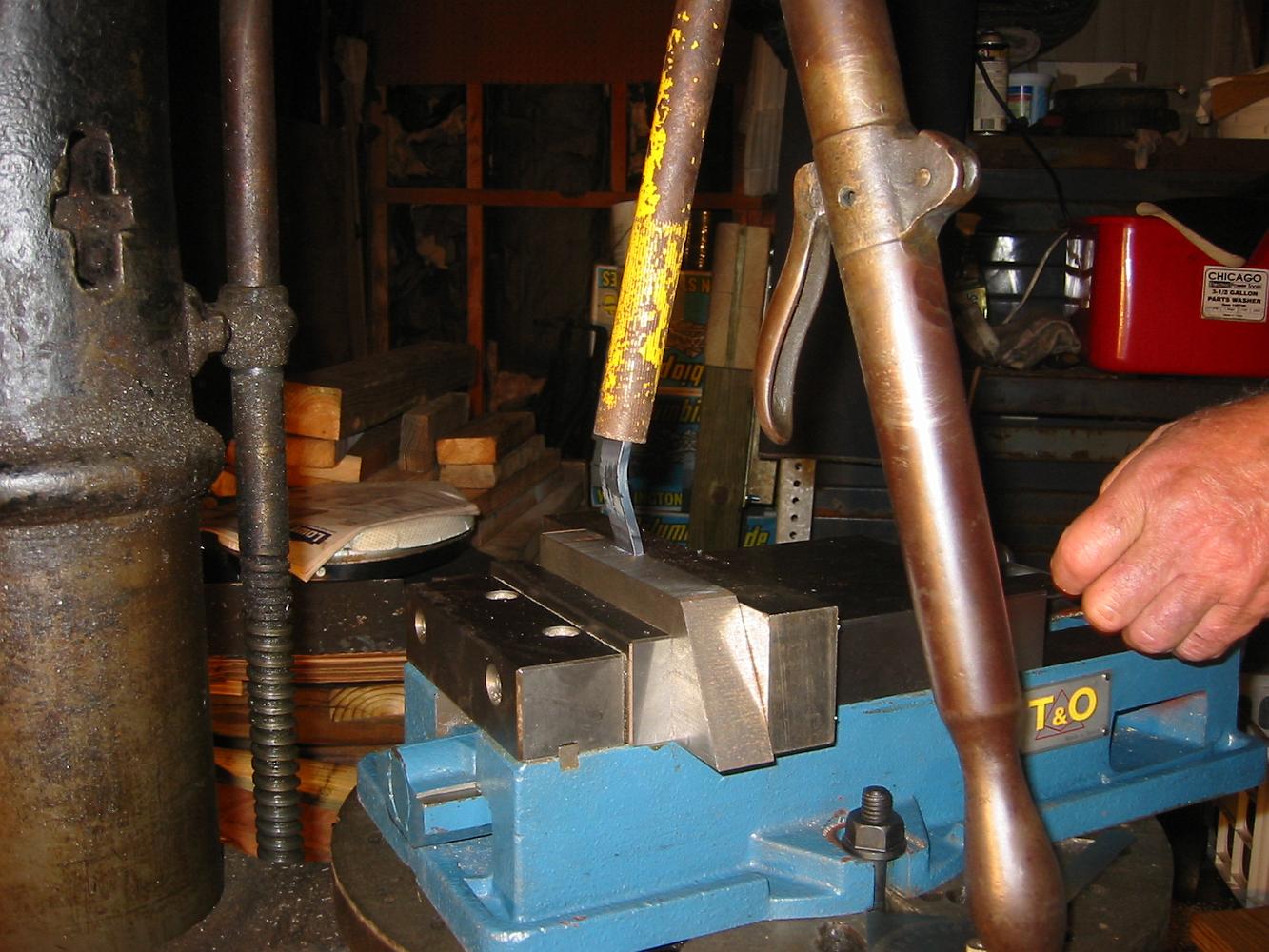
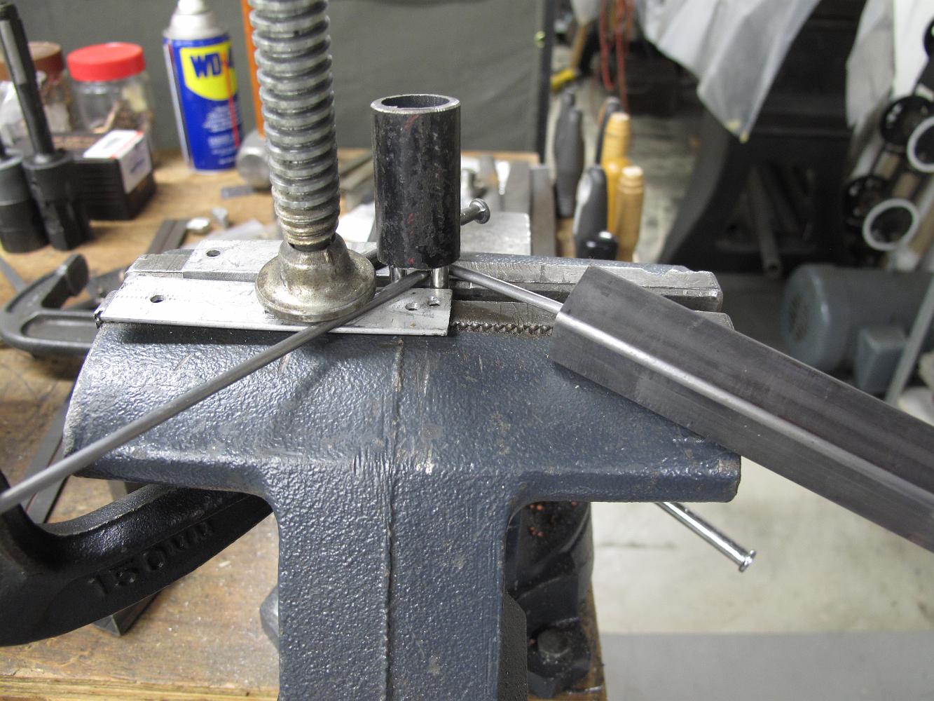
Bending the brackets. For the smaller lower ones we just used Vise-grips to hold them. The big machinist vice is clamped down on the antique Knight drill press…
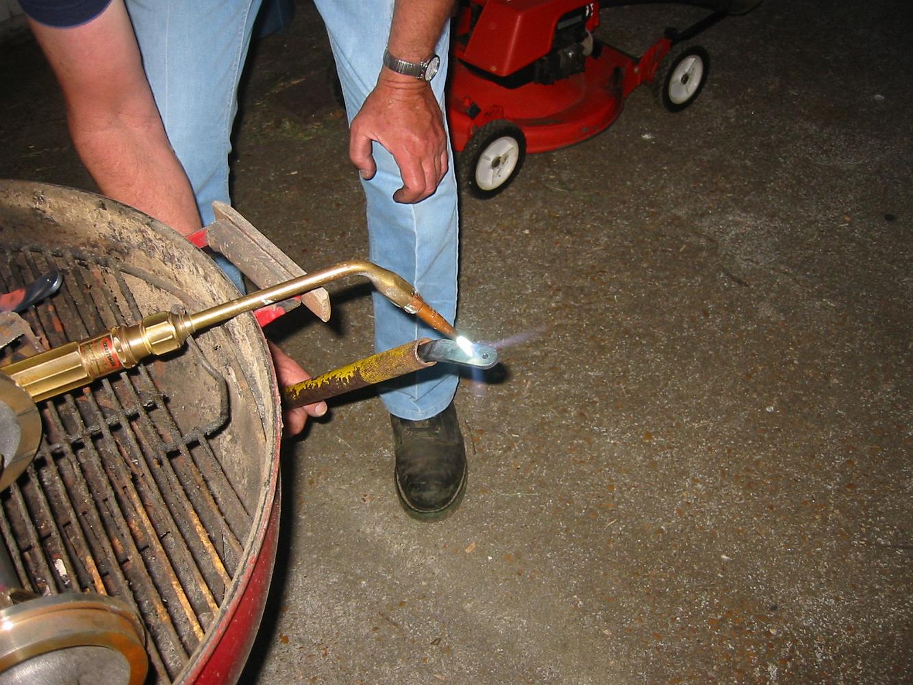
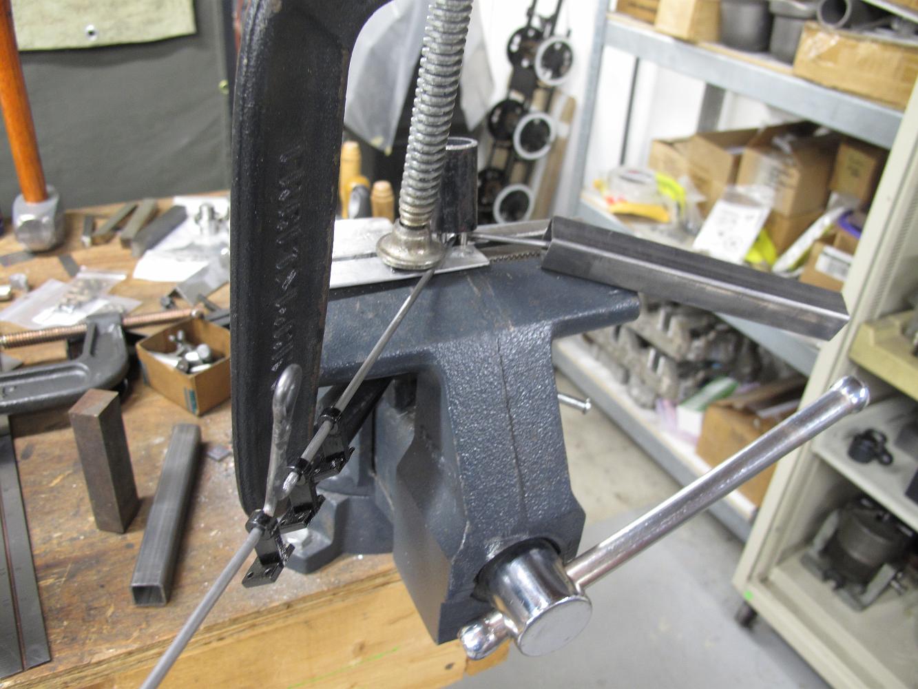
Putting the second bent in the bracket. The yellow pipe we are using as a bender is actually a handle for the floor jack.
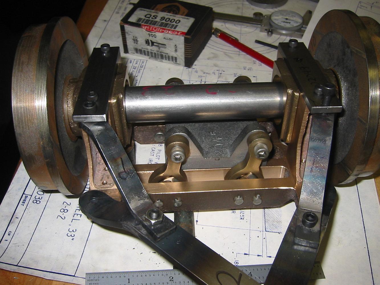
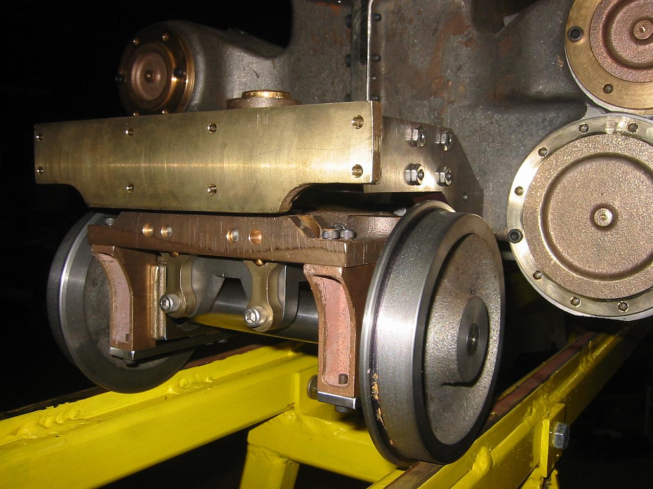
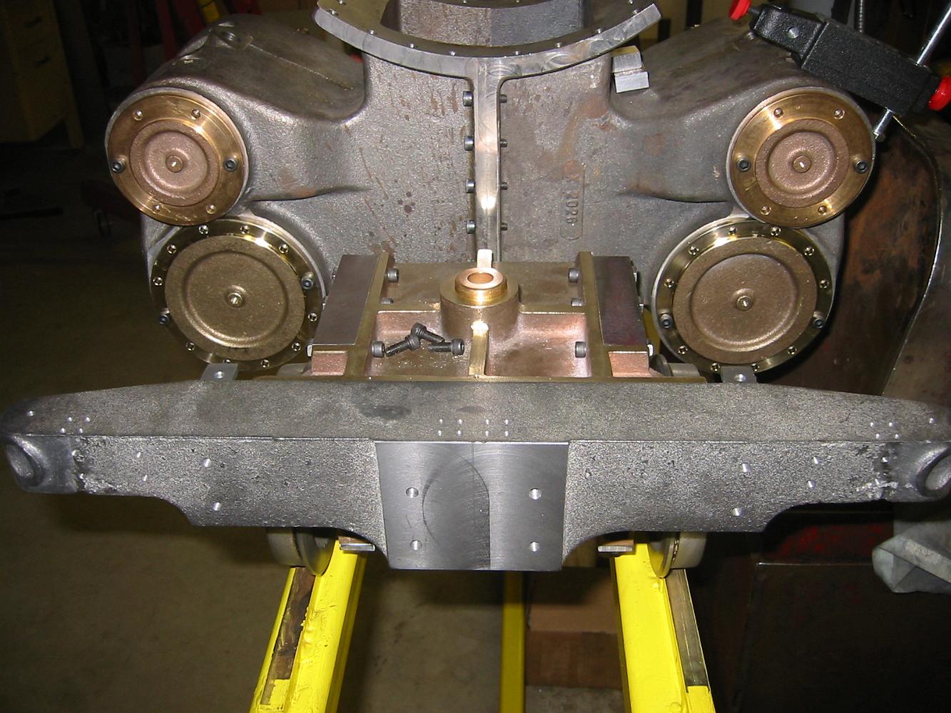
23-May-07 A trial assembly of the pilot truck! We still have to turn the wheels to profile and finish weld the bracket arms.
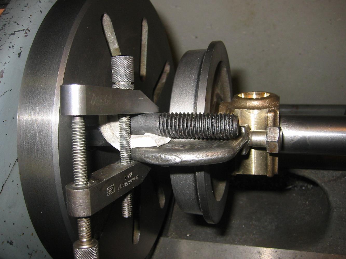
27-June-07 Anti-chatter setup we used when turning the wheel profile. The bolt is actually the driving dog stud, the white is a piece of rubber squeezed with…
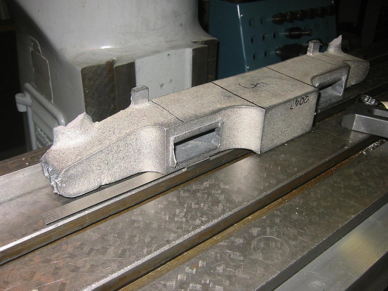
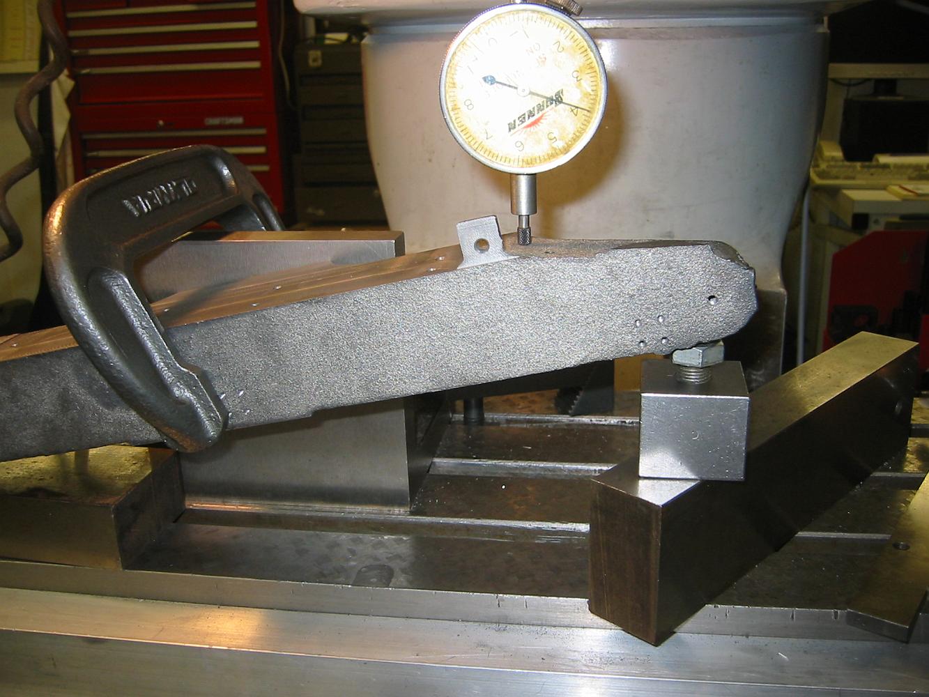
3-July-07 We start on the front bumper beam. Bill and I look at the print and it only calls for the little square tabs to be finished machined. Now I can't…
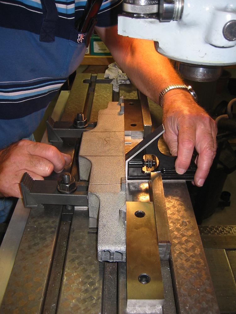
Due to the draft in the casting (taper), we decided to make the top surface the square reference point. Here Bill adjusts the casting for the back operations.
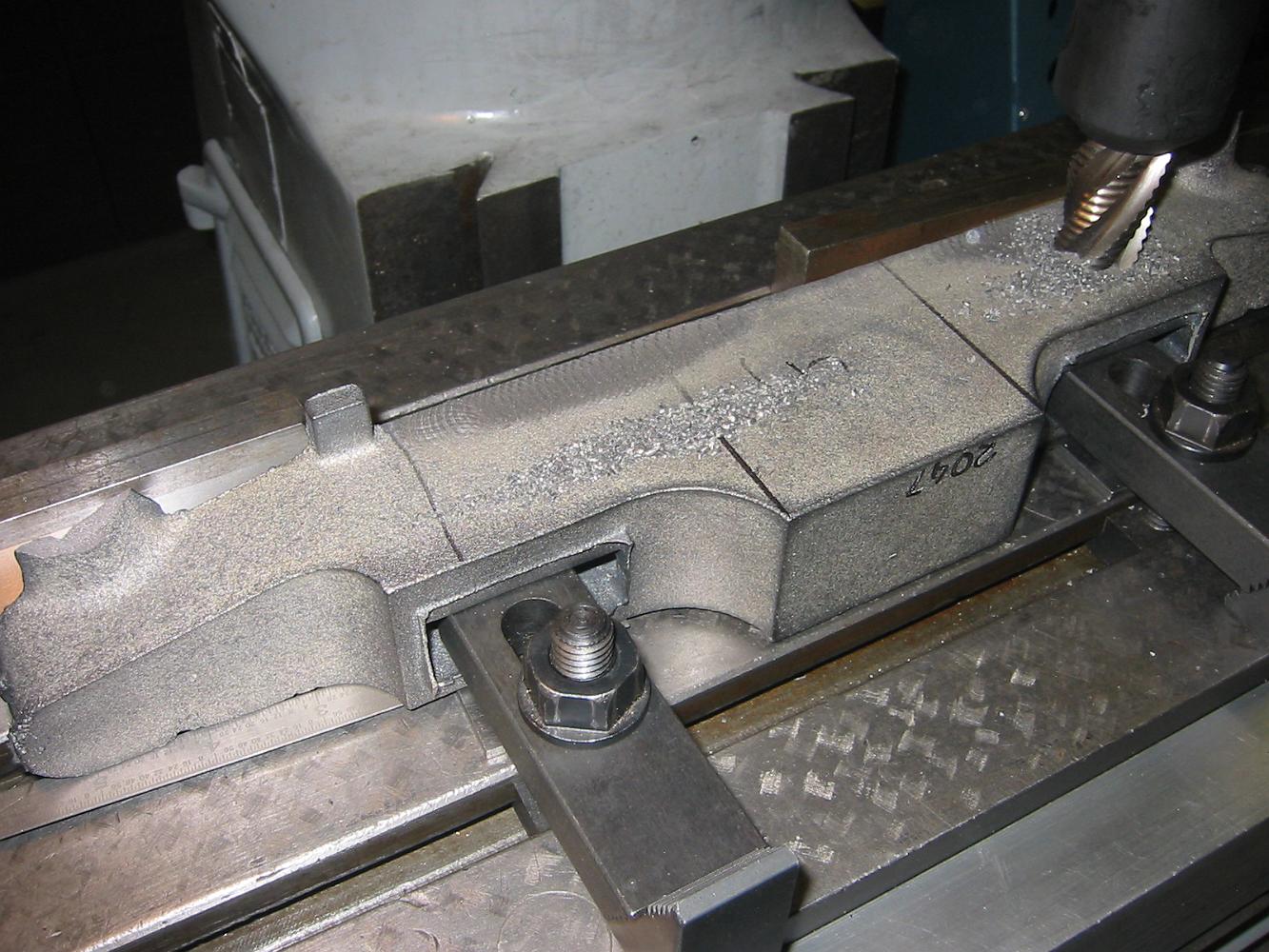
Machining the back, but only within the top tabs which will cover the front frame spreader contact surface.
With a machined reference surface on the back, we put some spacers on the table and machine the coupler pocket surface parallel to it.
Squaring up the angle plate to machine the bottom of the front bumper. We have to use the angle plate because the top of the bumper is unmachined, but the front…
11-July-07 Finishing the bumper top. Bill picks up the reference point the drawing specifies with the wiggler.
11-July-07 With the top done, we indicate the back as straight as we can with the casting to drill the holes in this end.
1-Aug-07 Bill shows me yet another setup for holding parts. In this case, we need to turn the flagstand, but the lantern bracket on the side of the flagstand…
1-Aug-07 The Flagstand held by the back of the chuck jaws so we can drill and counterbore. This setup allowed us to keep the same chucking as when we turned the…
1-Aug-07 Using a stop rod for the vice so we can 'mass produce' eight uncoupler lever brackets. Once we set the X and Y zeros, drilling the four holes per part…
6-Sept-09 Using a 5 degree tapered end mill, we bevel the bracket pivot hole to allow more vertical motion without enlarging the center bore of the hole. (No…
15-Sept-2013 Bending the coupler release lever in a rigged-up bending jig. Two dowel pins serve as bending points, a piece of pipe on top keeps them from…
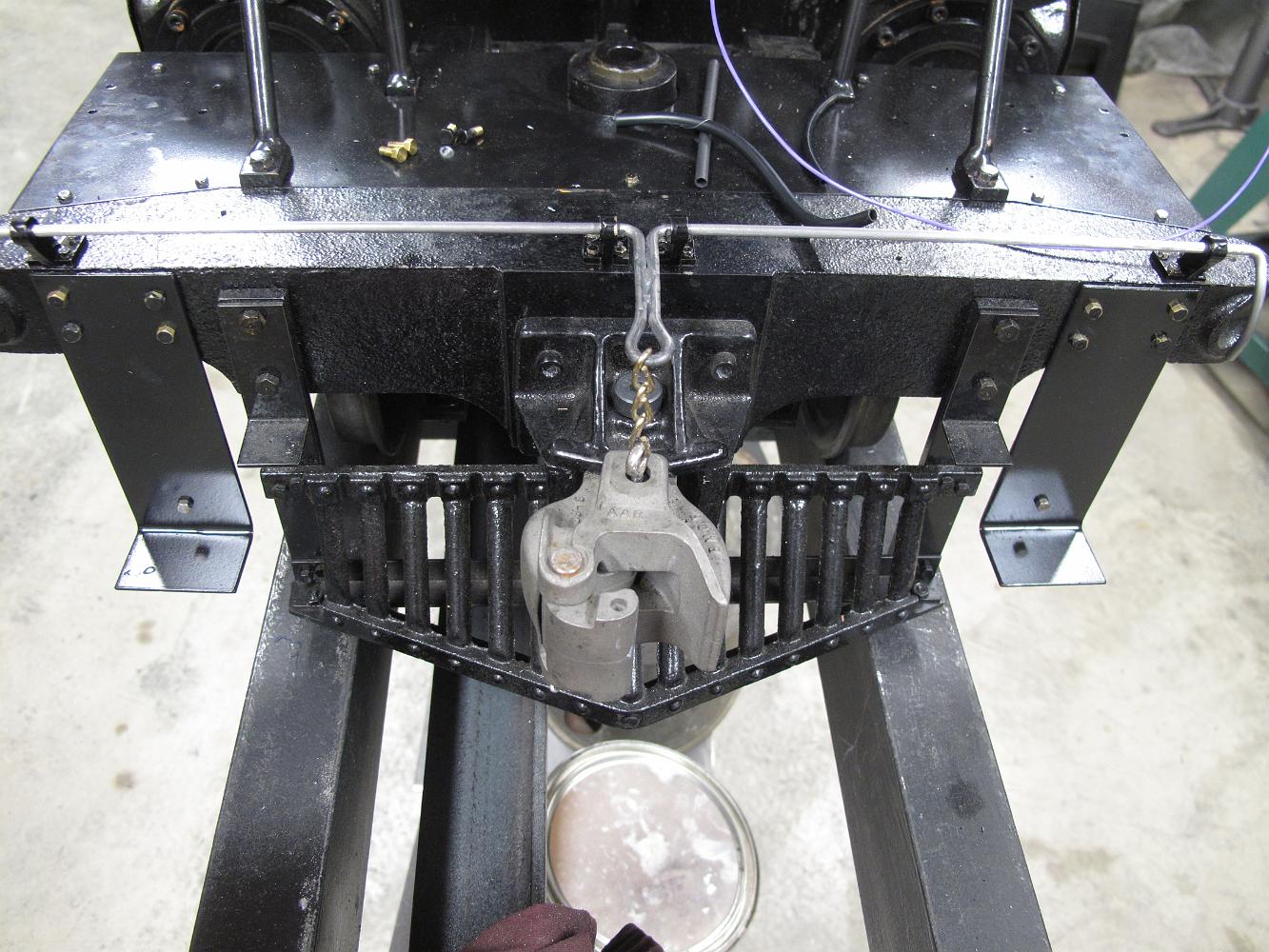
9-Feb-2012 The finished eye bolt installed on the modified front coupler. A touch of paint will finish it.
4-Feb-2012 Modifying the Superscale coupler to fit the RR Supply front coupler pocket. Machining off the two ears flush with the body.
6-Feb-12 Here's something I had not planned on doing - removing the front coupler pocket from the pilot bumper. The Loctite on the screws worked, it was had to…
6-Feb-12 Enlarging the coupler pin hole to 5/16". We also move the hole 0.062 closer to the front edge of the pocket so the coupler will fit better.
6-Feb-12 Custom fitting the SuperScale coupler to the RR Supply coupler pocket. With a center punched wooden plug in the pin hole, we scribe a line just under…
6-Jan-12 The rotary table is put back on to machine the front lip of the couple pocket. Here we are centering the table under the spindle.
6-Feb-12 The coupler will not go deep enough into the pocket with the as-cast support lip. We have to remove some of the lip. With an angle block bolted to the…
6-Feb-12 Machining the front support lip to fit the SuperScale coupler. Although we centered the rotary table under the spindle, and centered the coupler pocket…
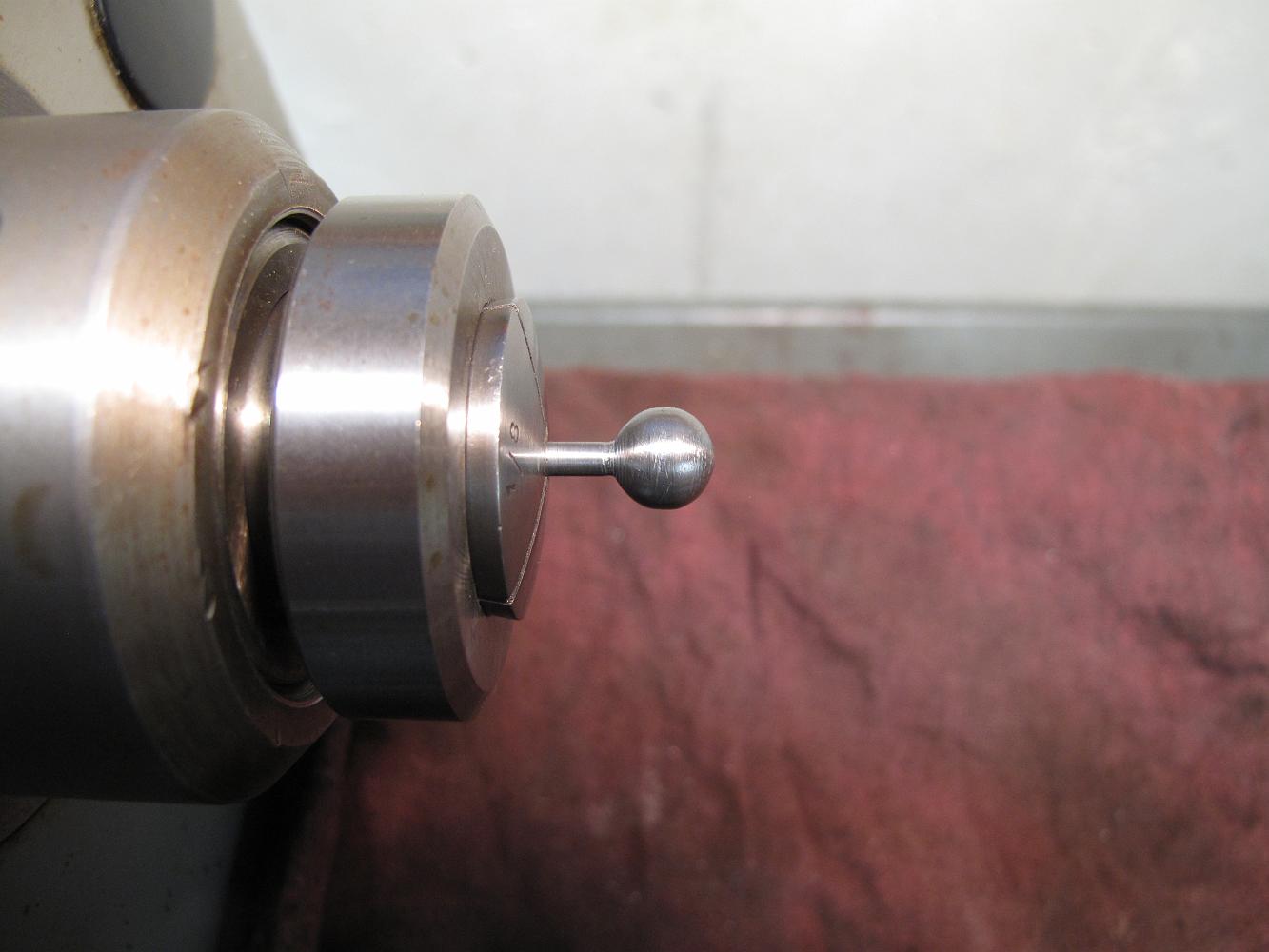
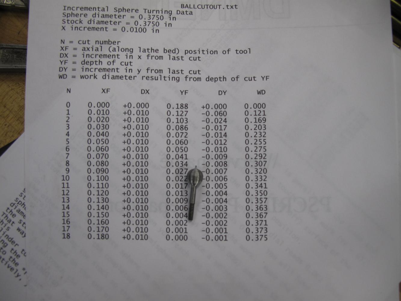
6-Feb-12 Finished the night fabricating an eyebolt for the coupler pin. First step was to turn and thread a 5-40 bolt end. Using Marv Klotz's simple program…
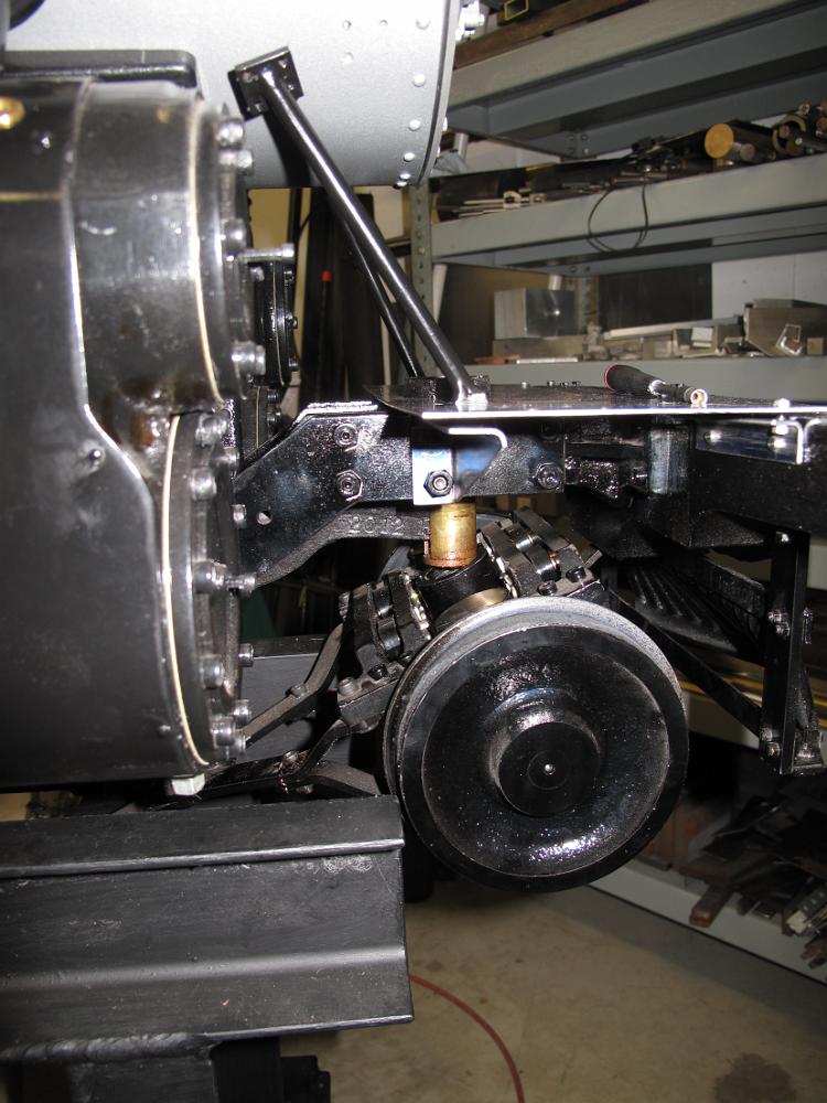
30-Jan-12 The problem of waiting so long to finish this section: with the pilot truck assembled and installed, there is no way for me to get my fingers under…
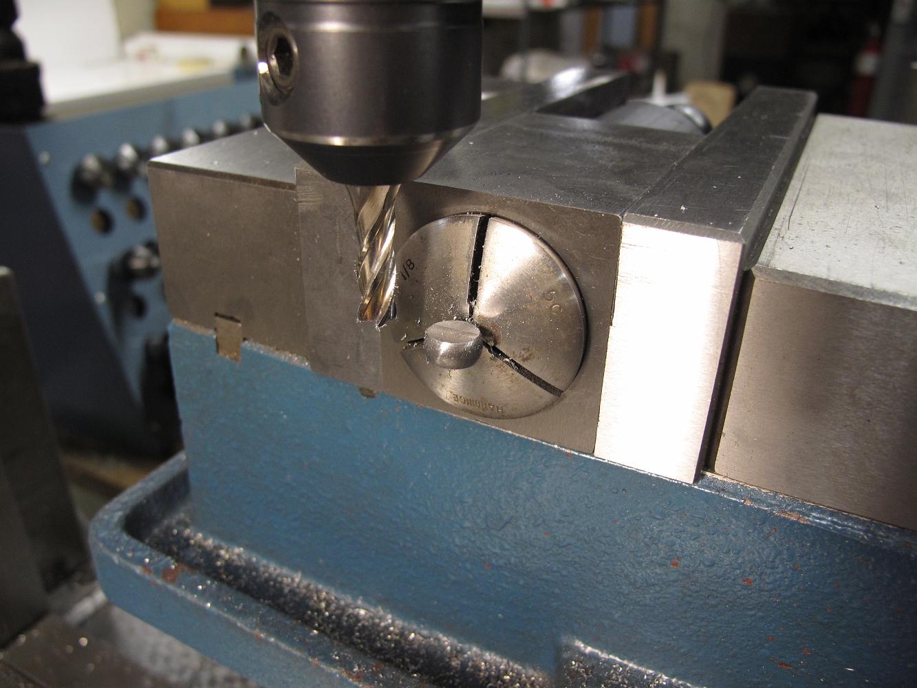
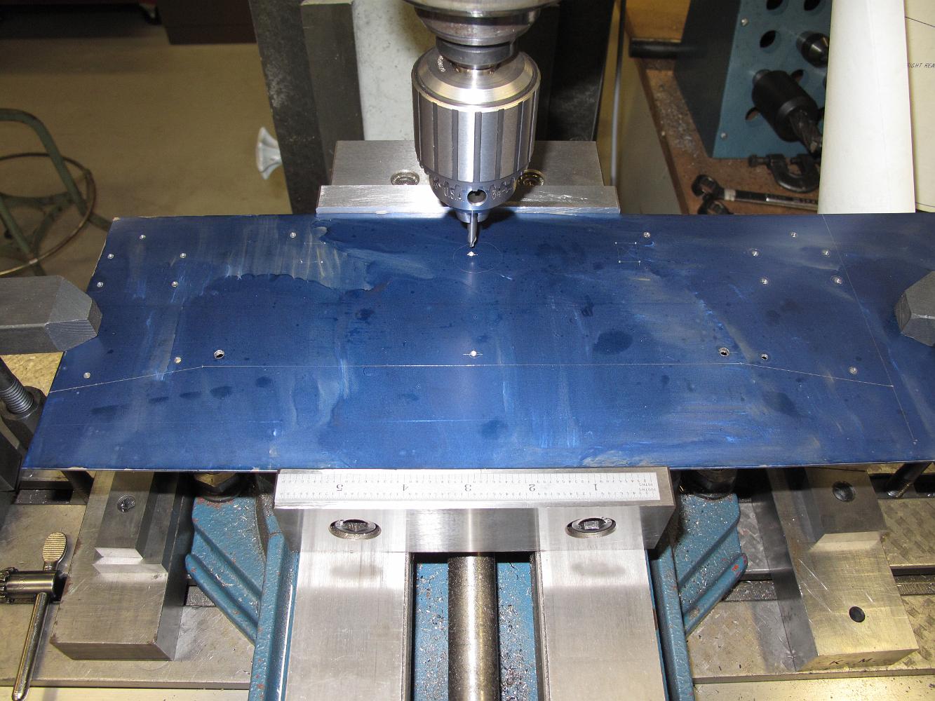
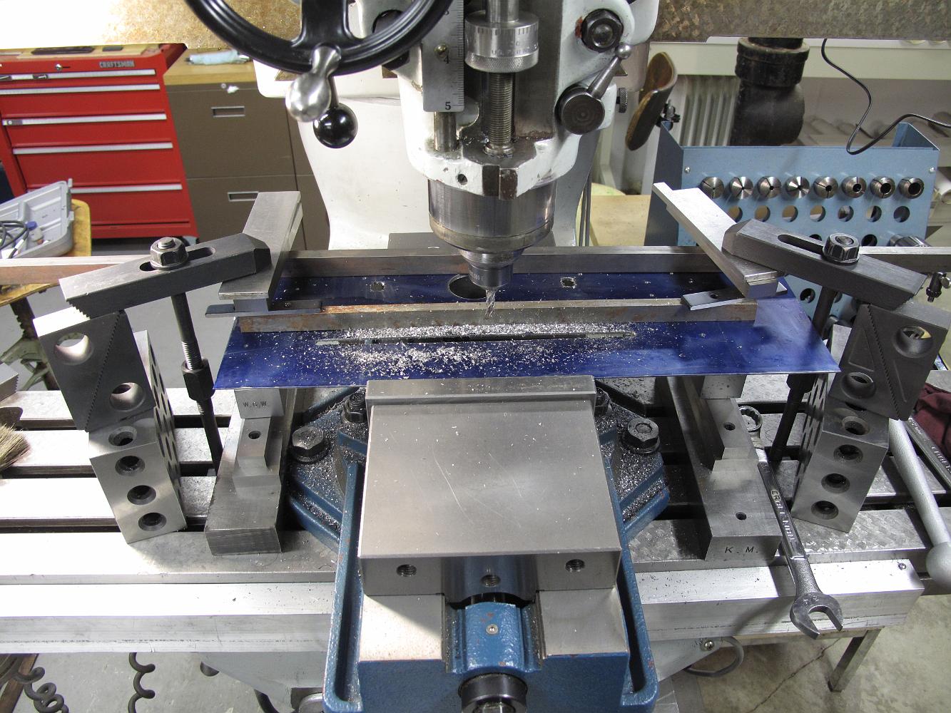
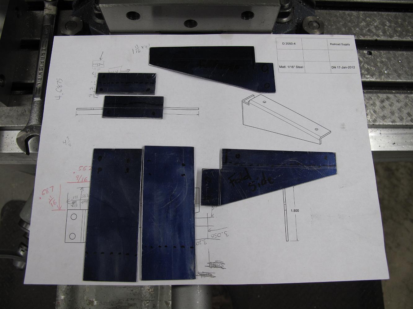
19-Jan-2012 I have covered a piece of 16 gauge (1/16") mild steel sheet with blue layout dye, and clamped it in the vise with a rather suspicious hold-down…
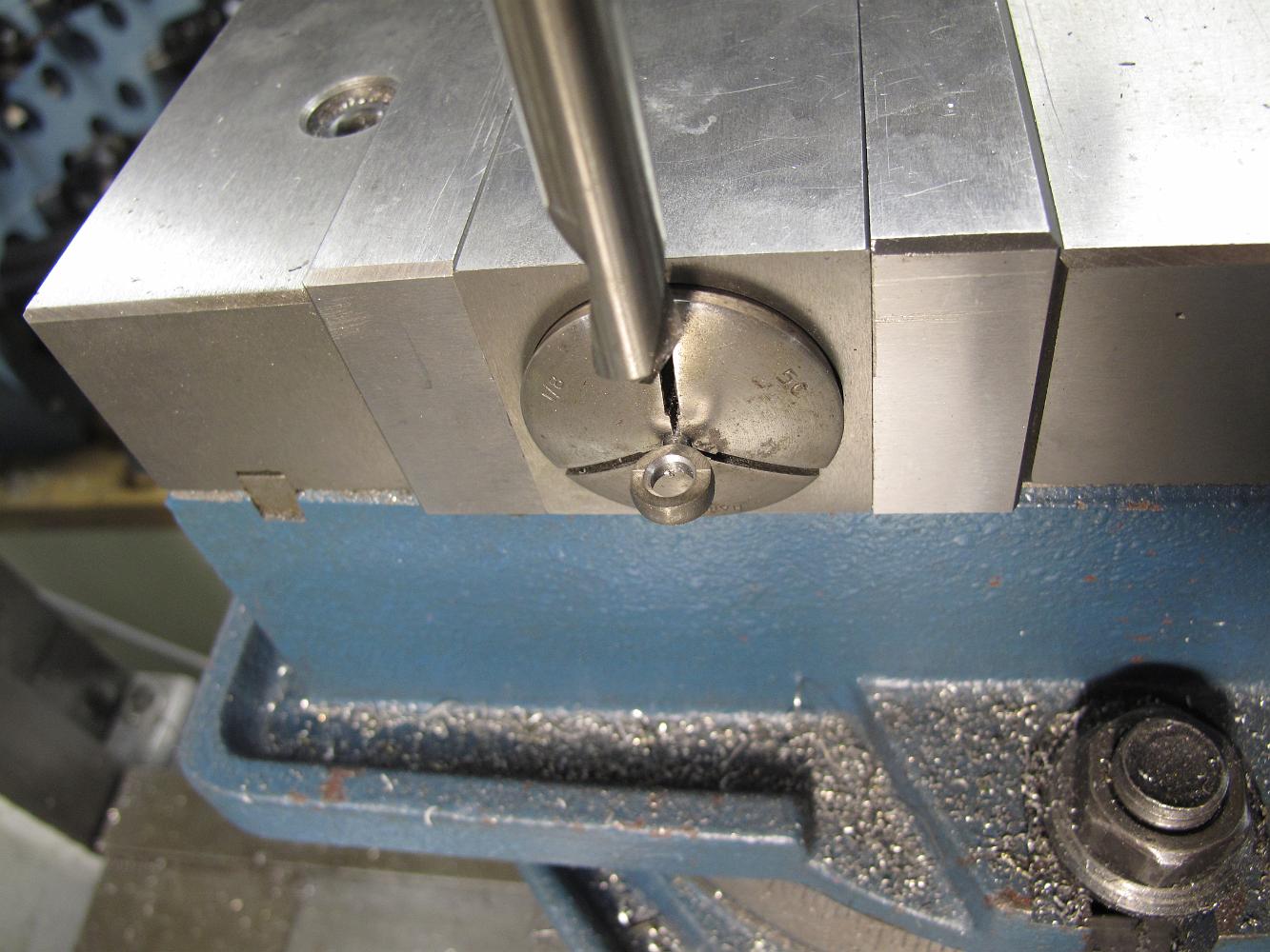
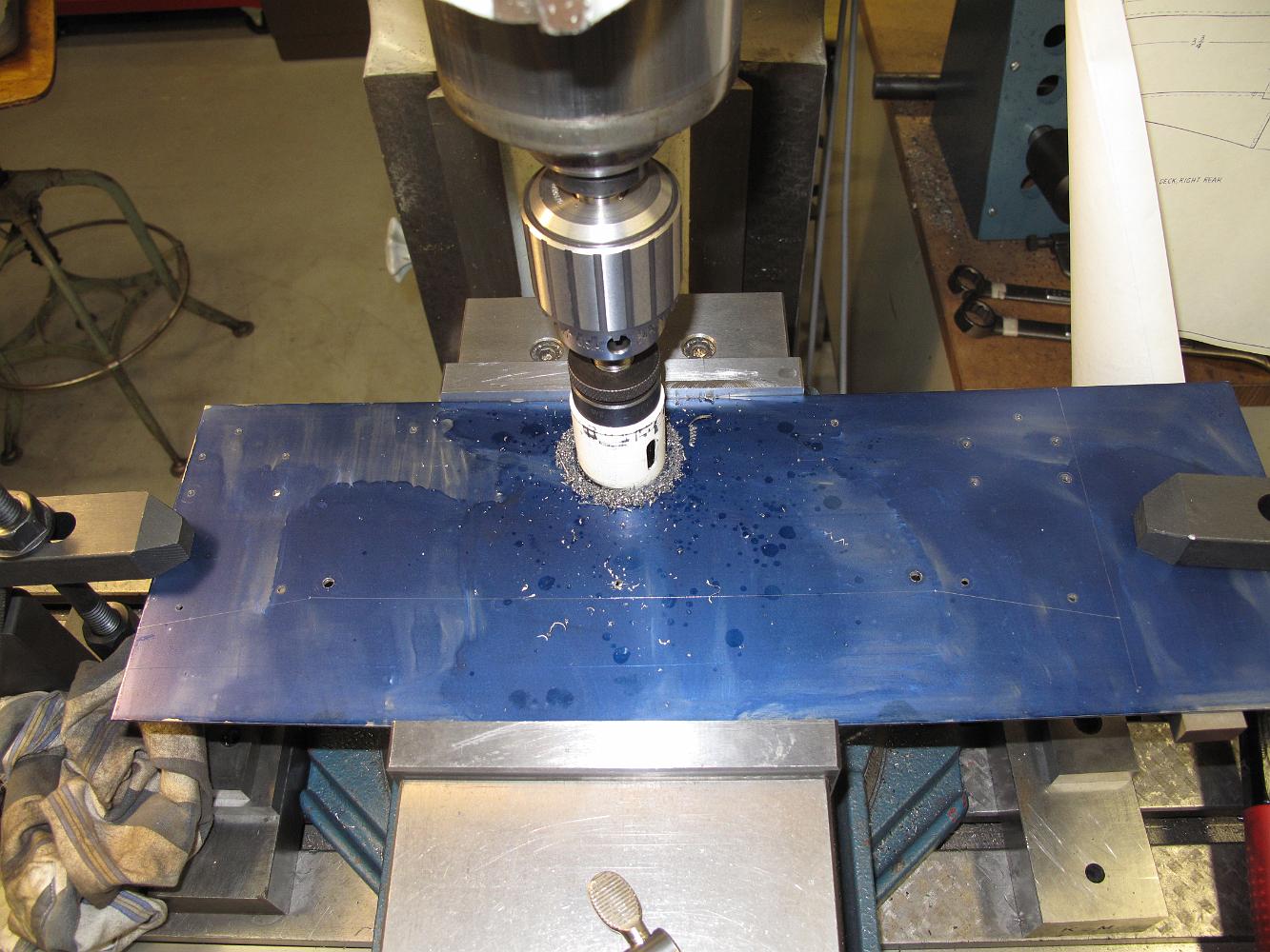
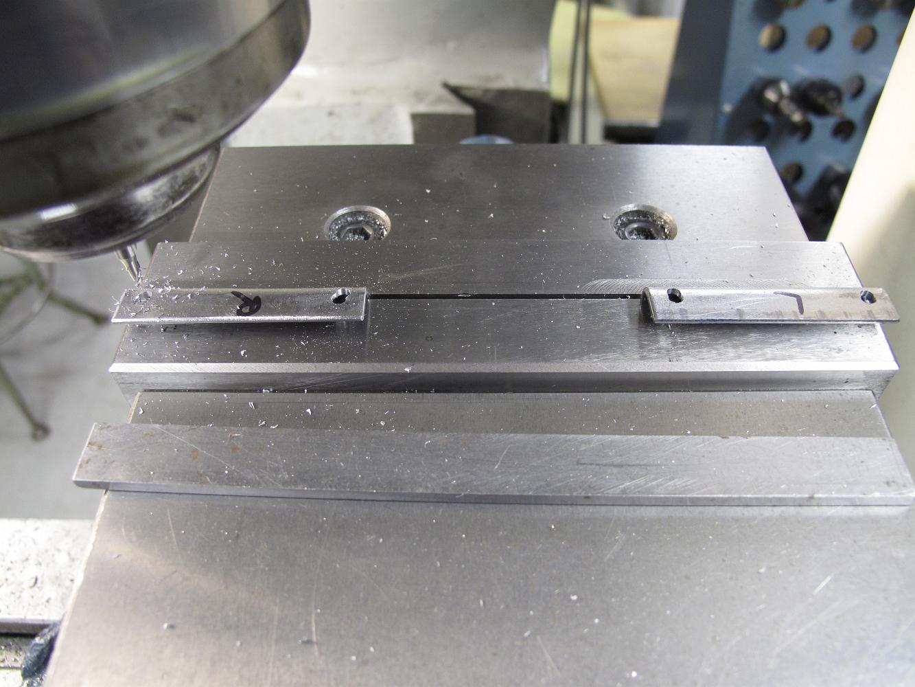
19-Jan-2012 Having finished drilling all the small holes, and re-clamping the setup so I don't drill holes in the vise, I use my favorite quick and dirty method…
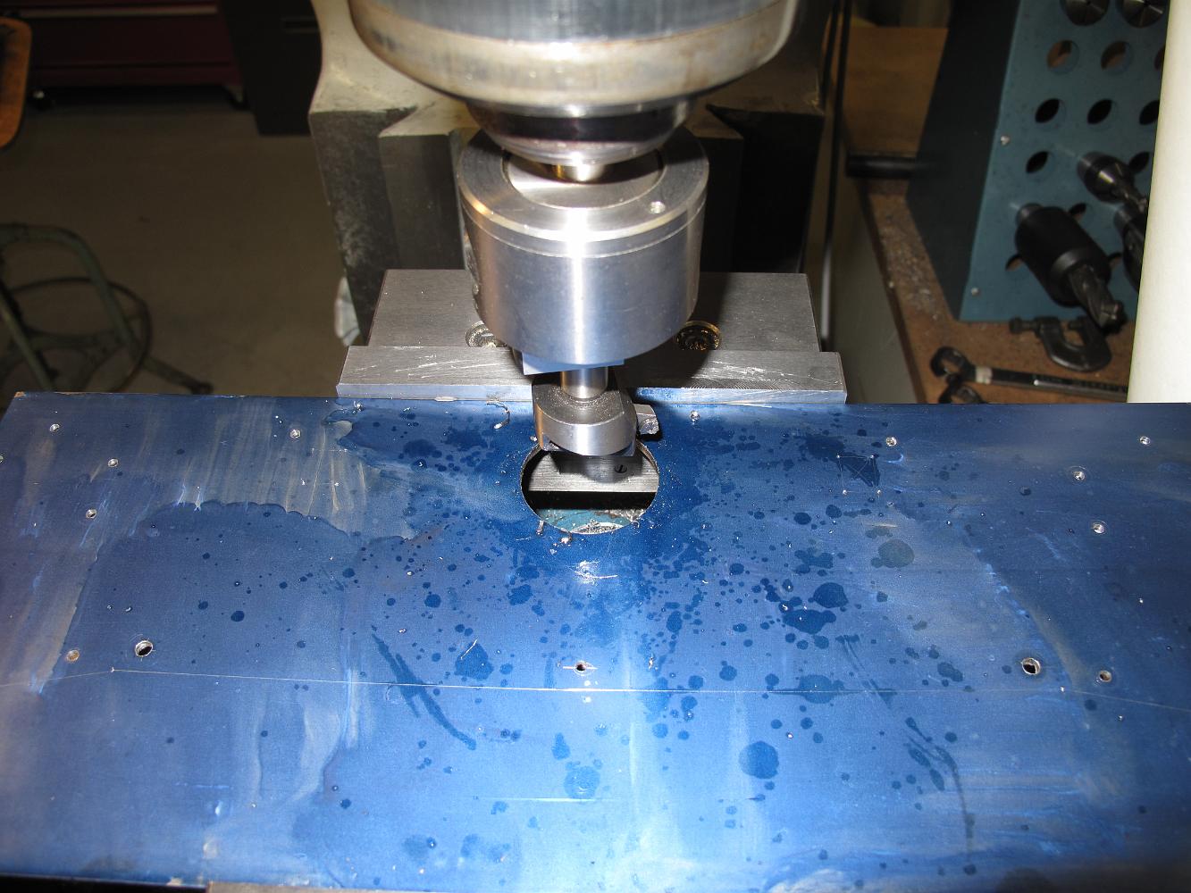
19-Jan-12 One ugly setup. I almost didn't publish this, but here's what it comes down to: The sheet metal was clamped down across the vice, the vice was not…
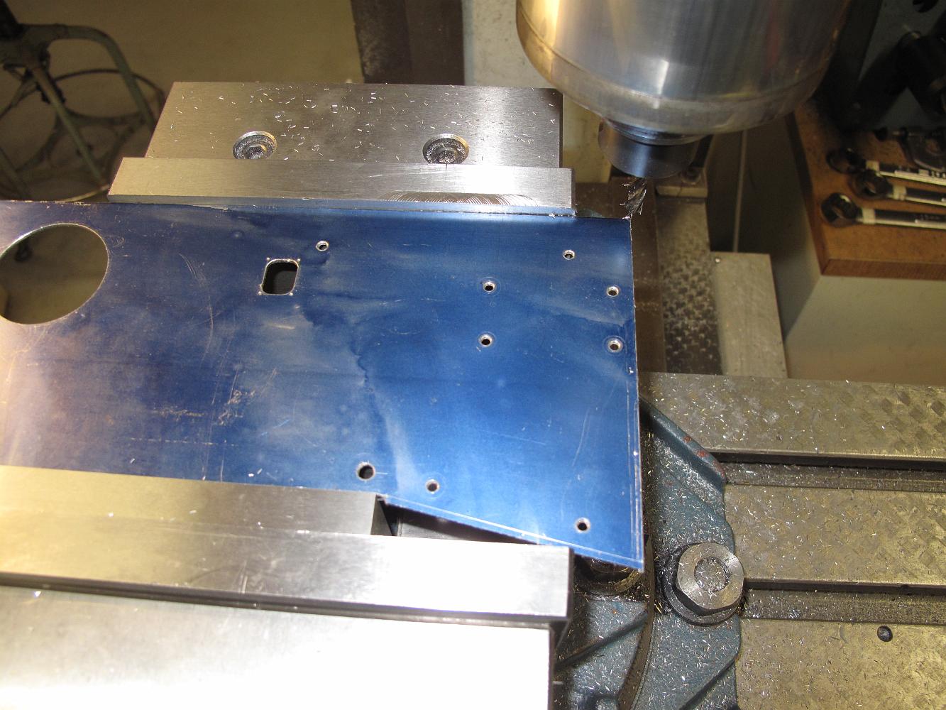
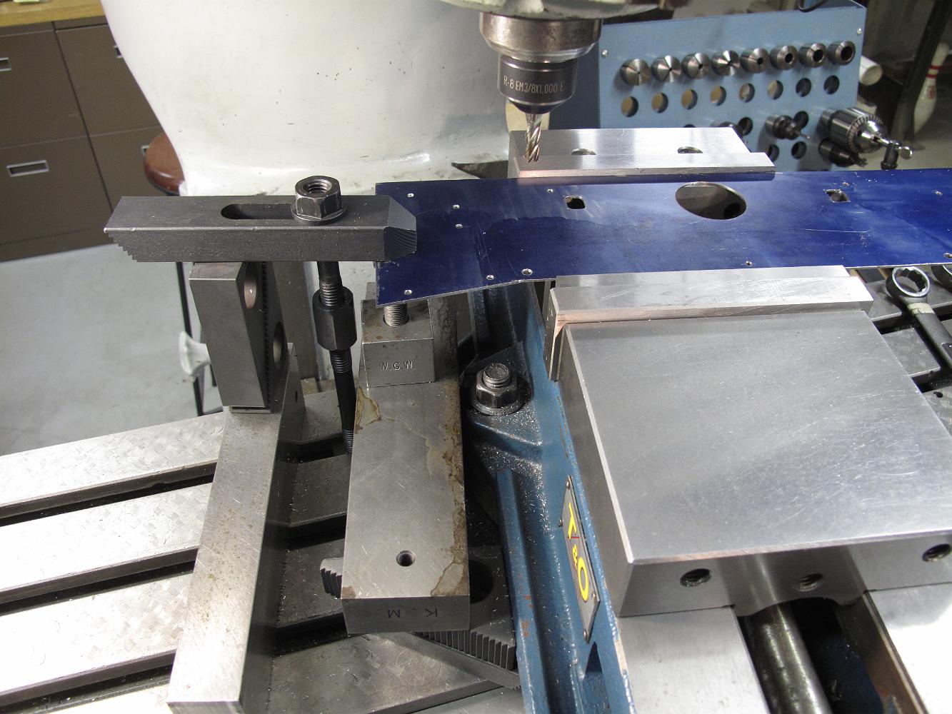
19-Jan-12 Trimming the front angled parts of the deck. I calculated the angle to be 12 degrees. I unlocked the swivel base on my vise, swung it to 12 degrees…