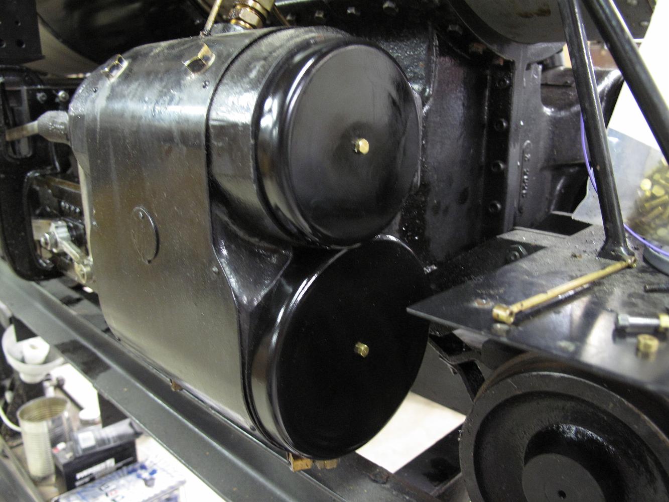
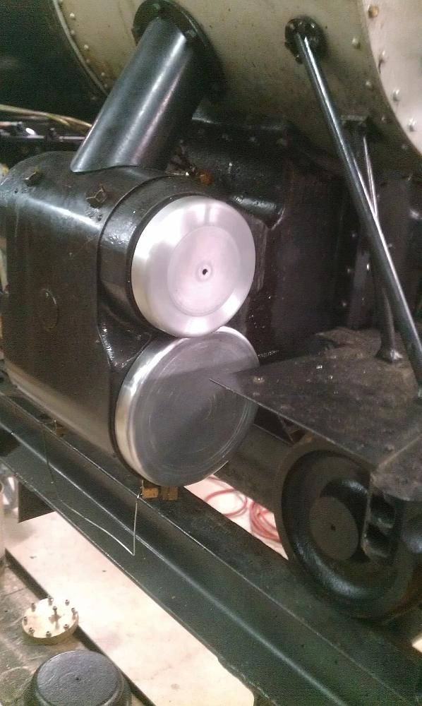
13-Apr-2015 Finished Cylinder covers installed
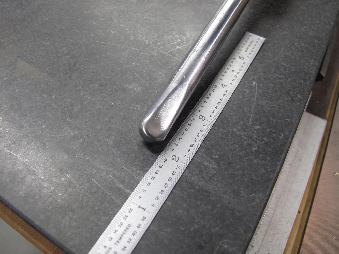
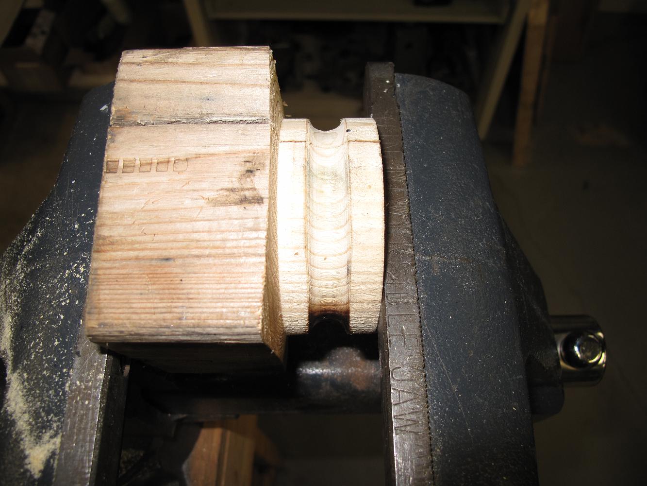
18-Feb-2014 Shop made spinning tool.
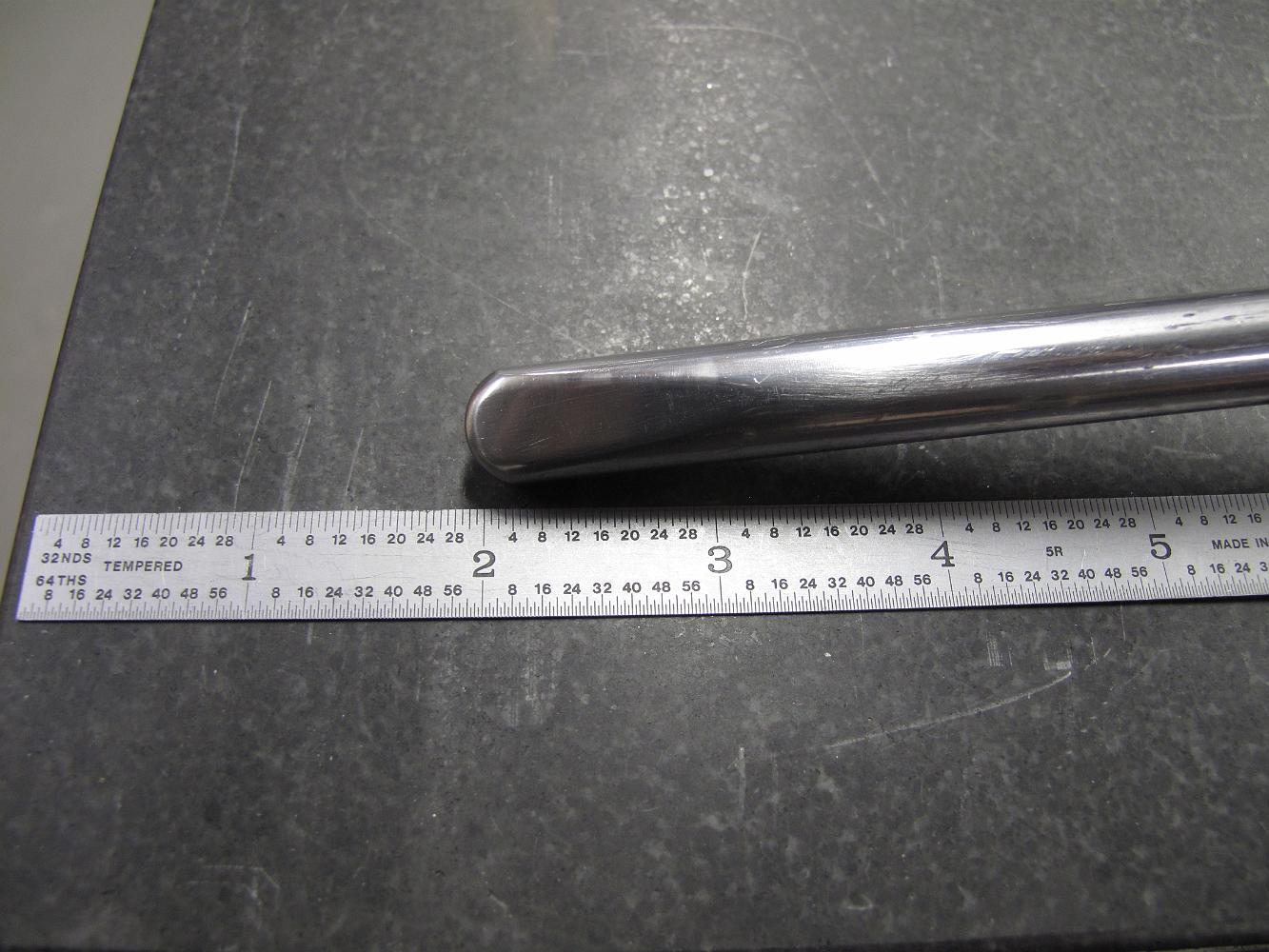
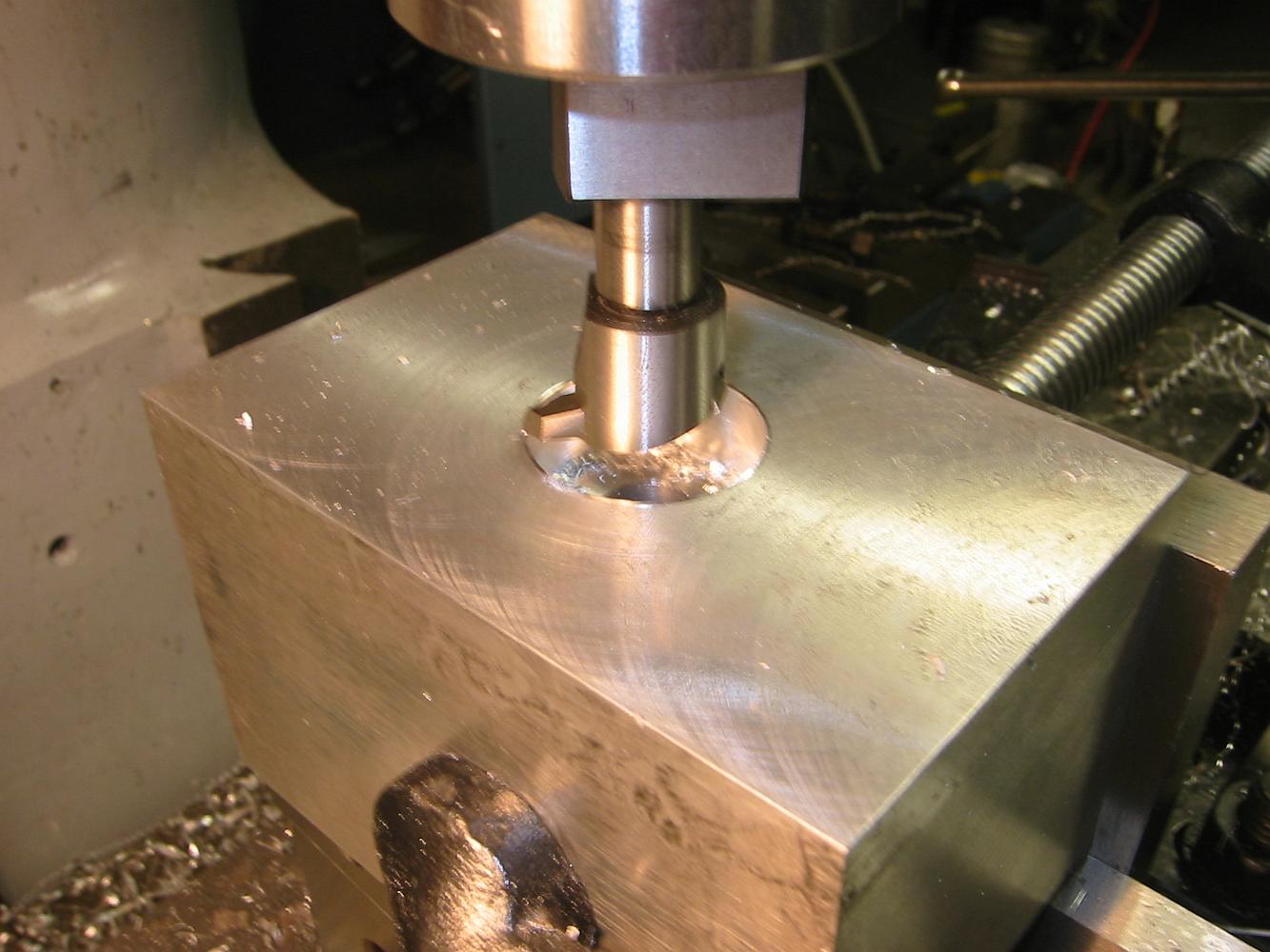
18-Feb-2014 Shop made spinning tool. 1/2" O-1 Oil hardening tool steel. We first rounded the end, then milled the flat. I spent some time with the buffer…
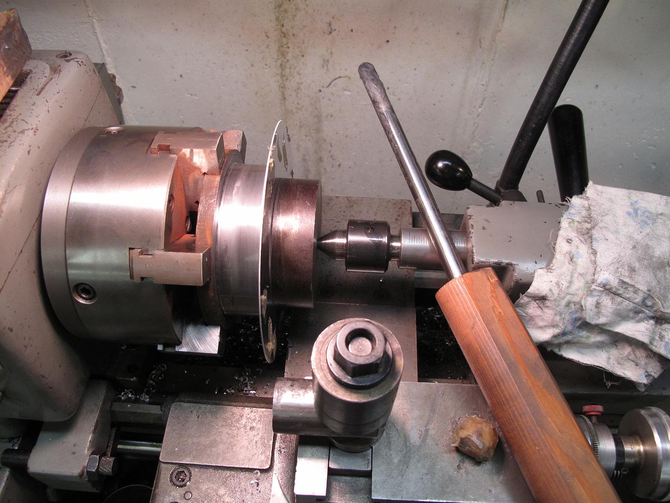
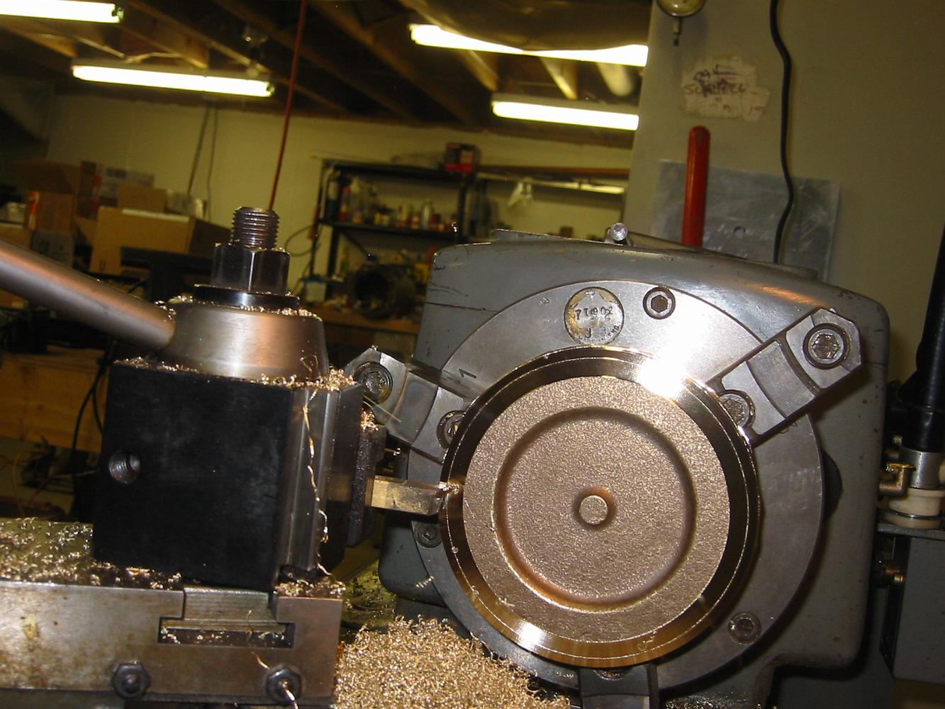
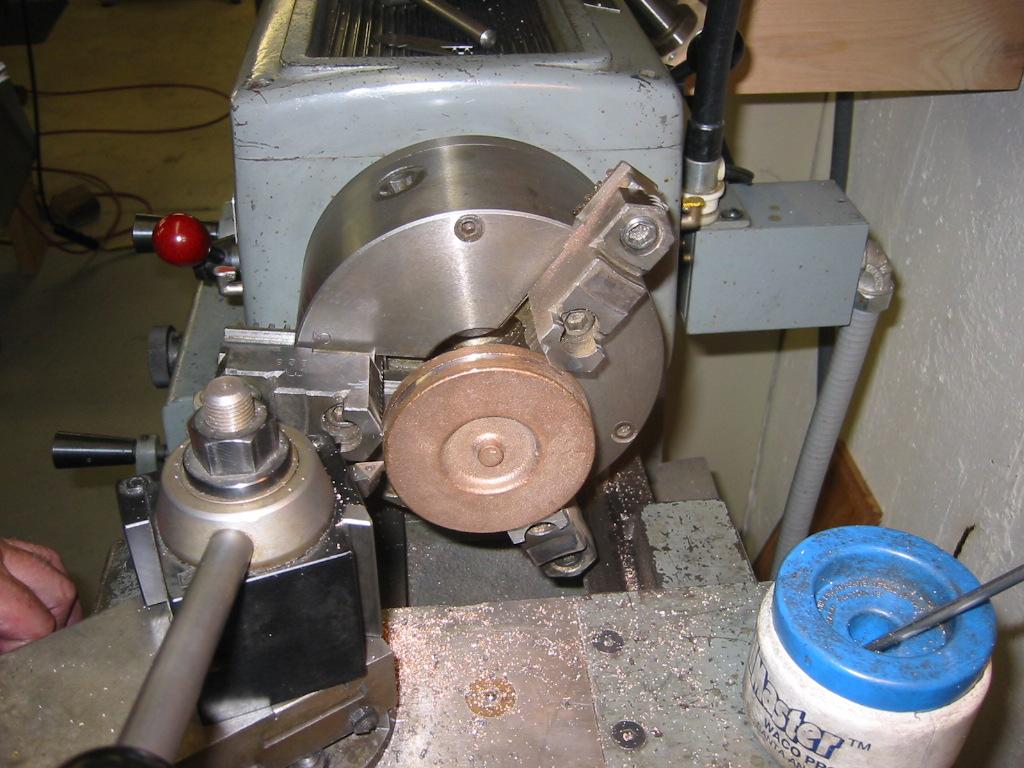
18-Nov-2014 Spun cover ready to be trimmed to size using the cutoff tool. In my setup, I have to remove the tool rest from the cross slide and put the cutoff…
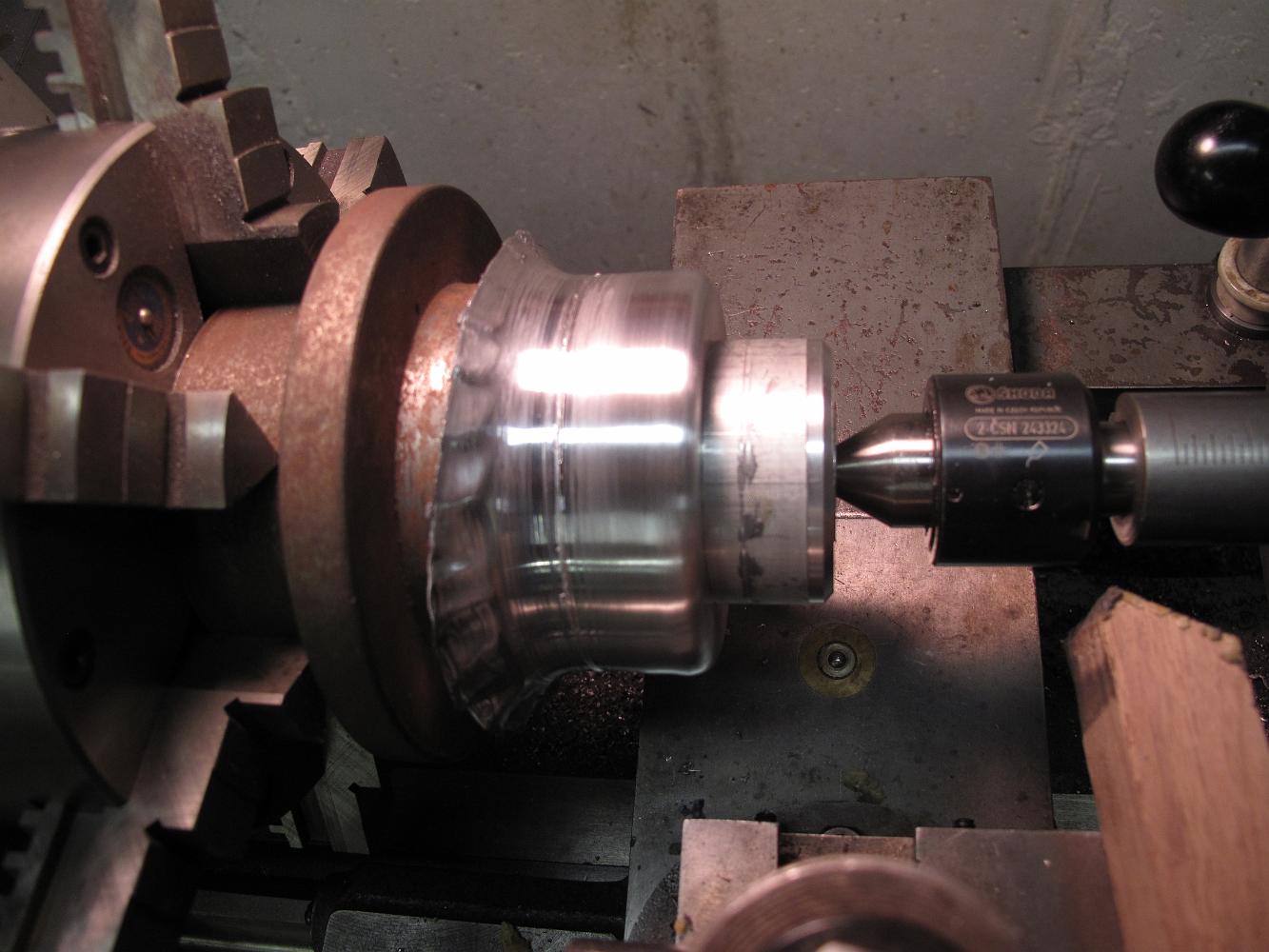
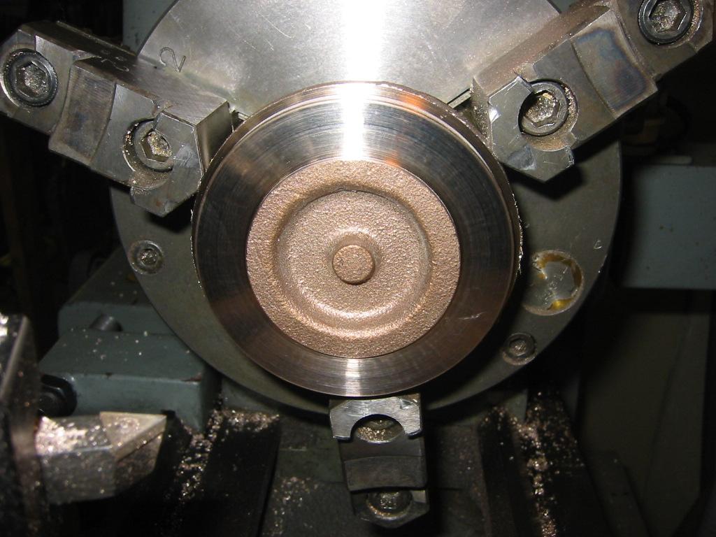
18-Nov-2014 First spinning operation completed, ready to be removed and excess trimmed. You can see some of the buckling problem I am having when folding the…
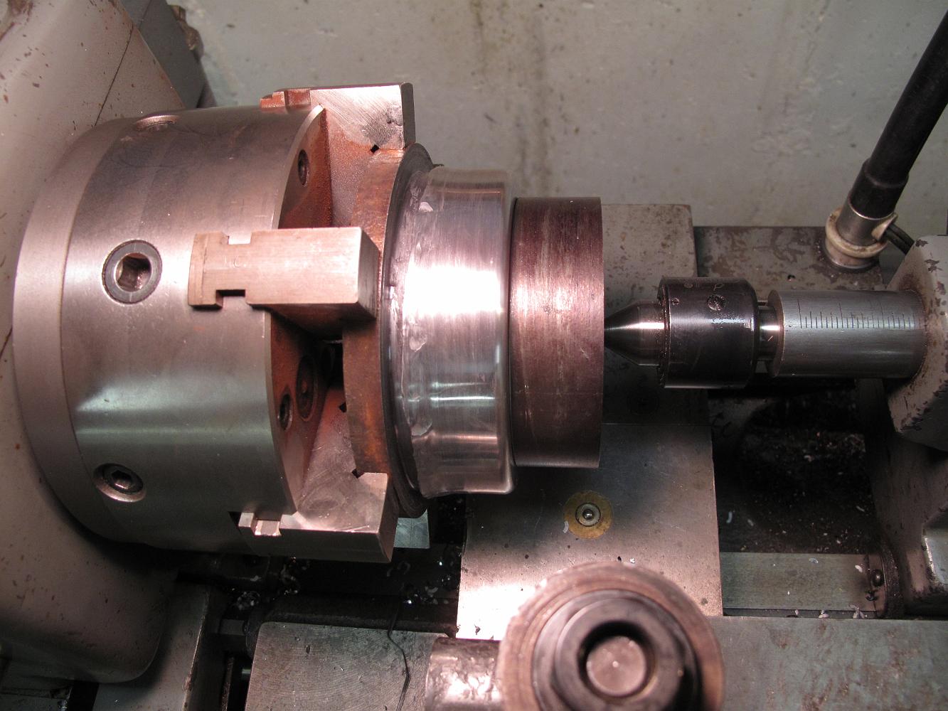
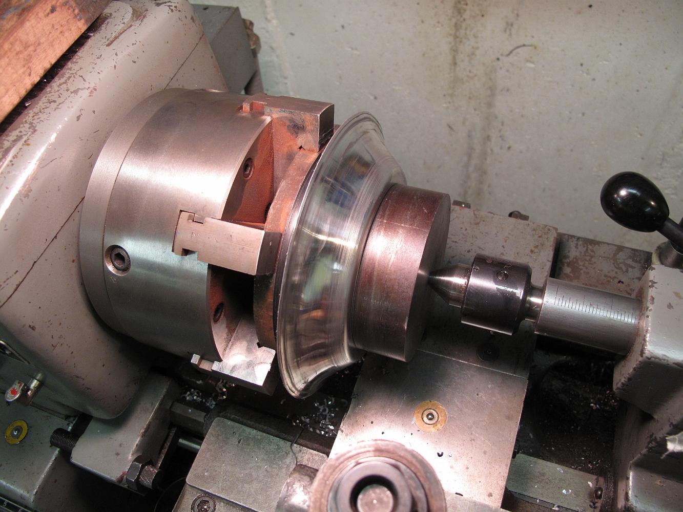
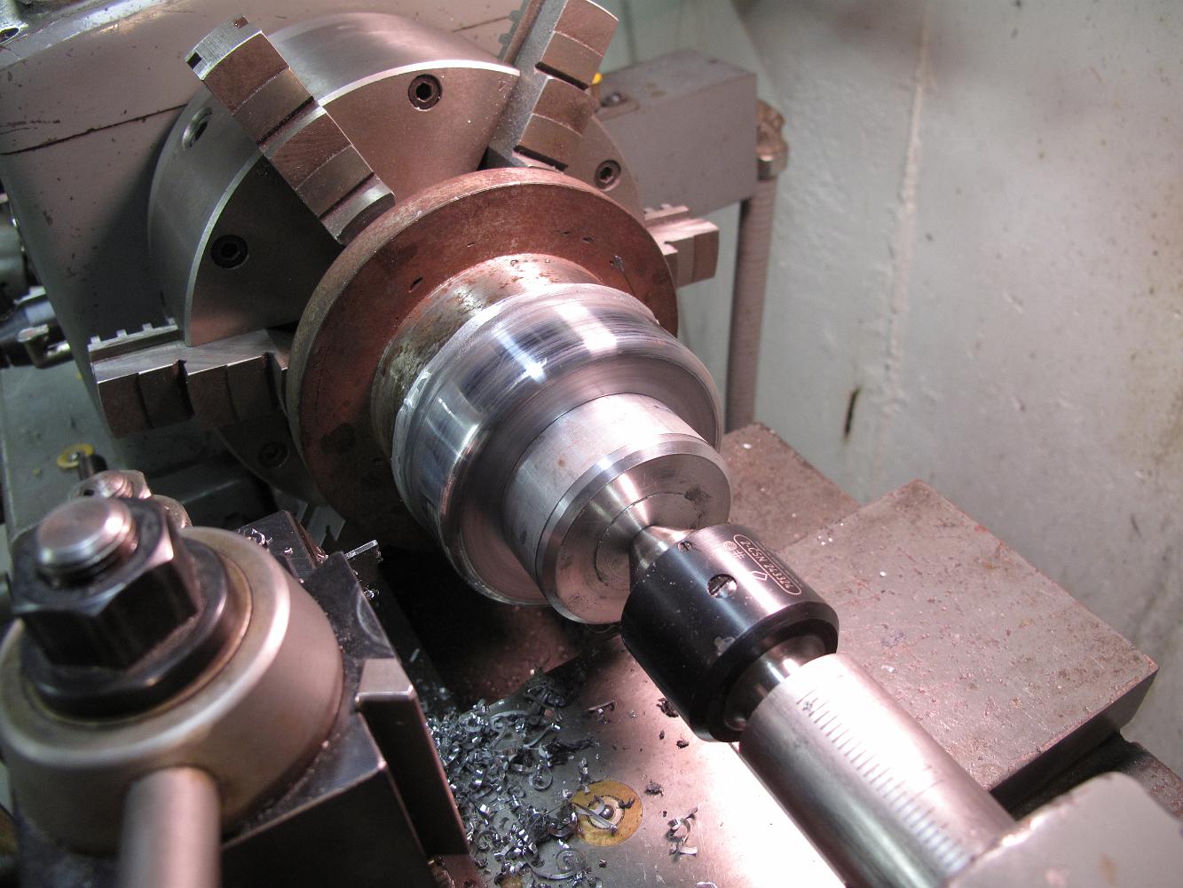
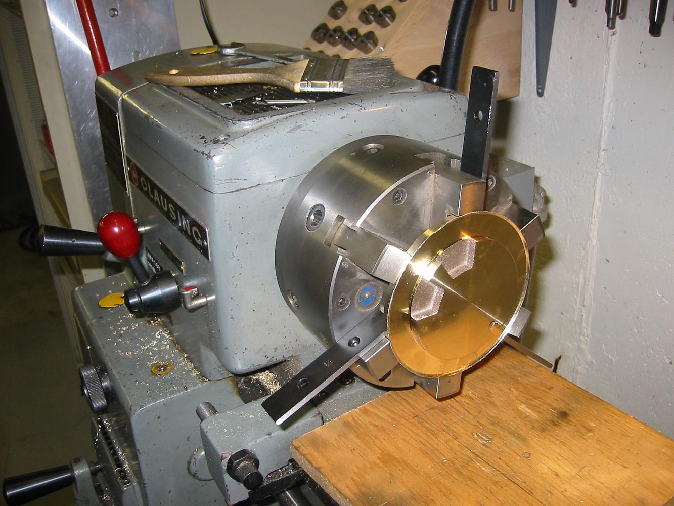
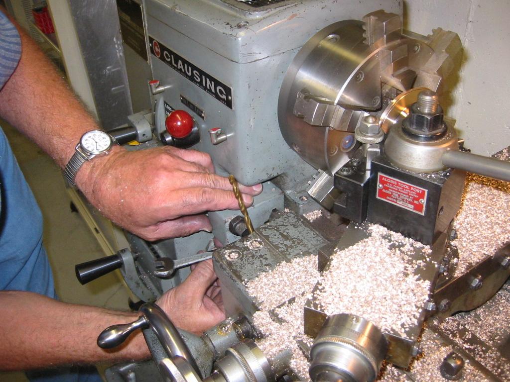
18-Nov-2014 Here's my metal spinning setup in my metal lathe for the piston covers: Steel mandrel chucked up. I would recommend a mandrel which is not chucked…
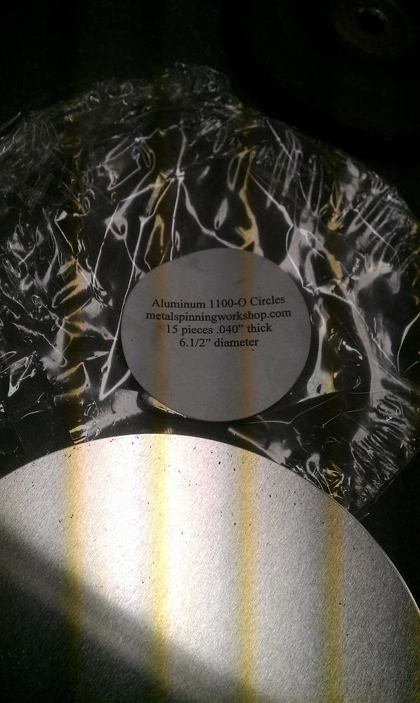
18-Nov-2014 I am using dead soft 1100-0 Aluminum 0.040 thick round blanks for the covers. I ordered them from a now defunct website back in 2000 (I think).
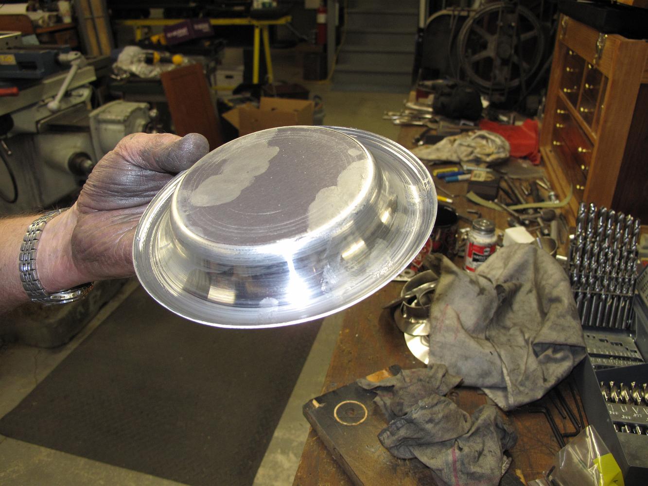
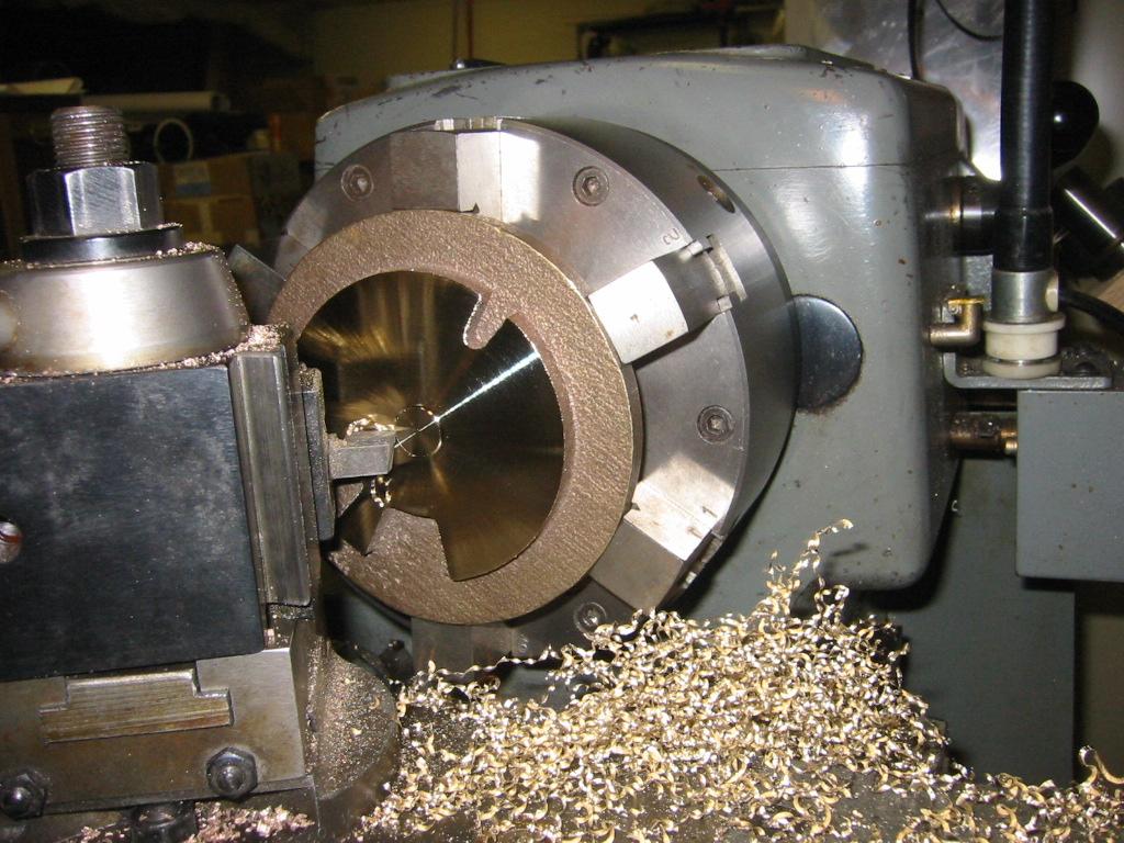
17-Nov-2014 It takes me several passes to spin the covers down to the finished size. I have problems with the metal buckling once I have started shrinking the…
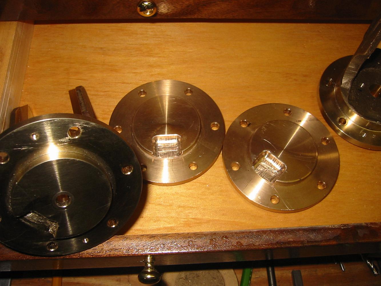
17-Nov-2014 Test fitting of two new front covers. The metal spinning was not has hard as I first thought.
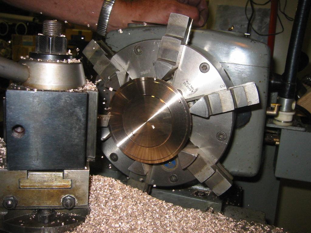
16-Nov-2014 Metal spinning setup: Steel forming mandrel chucked, spun cover ready to be trimmed to size using a parting tool, aluminum holding block held by…
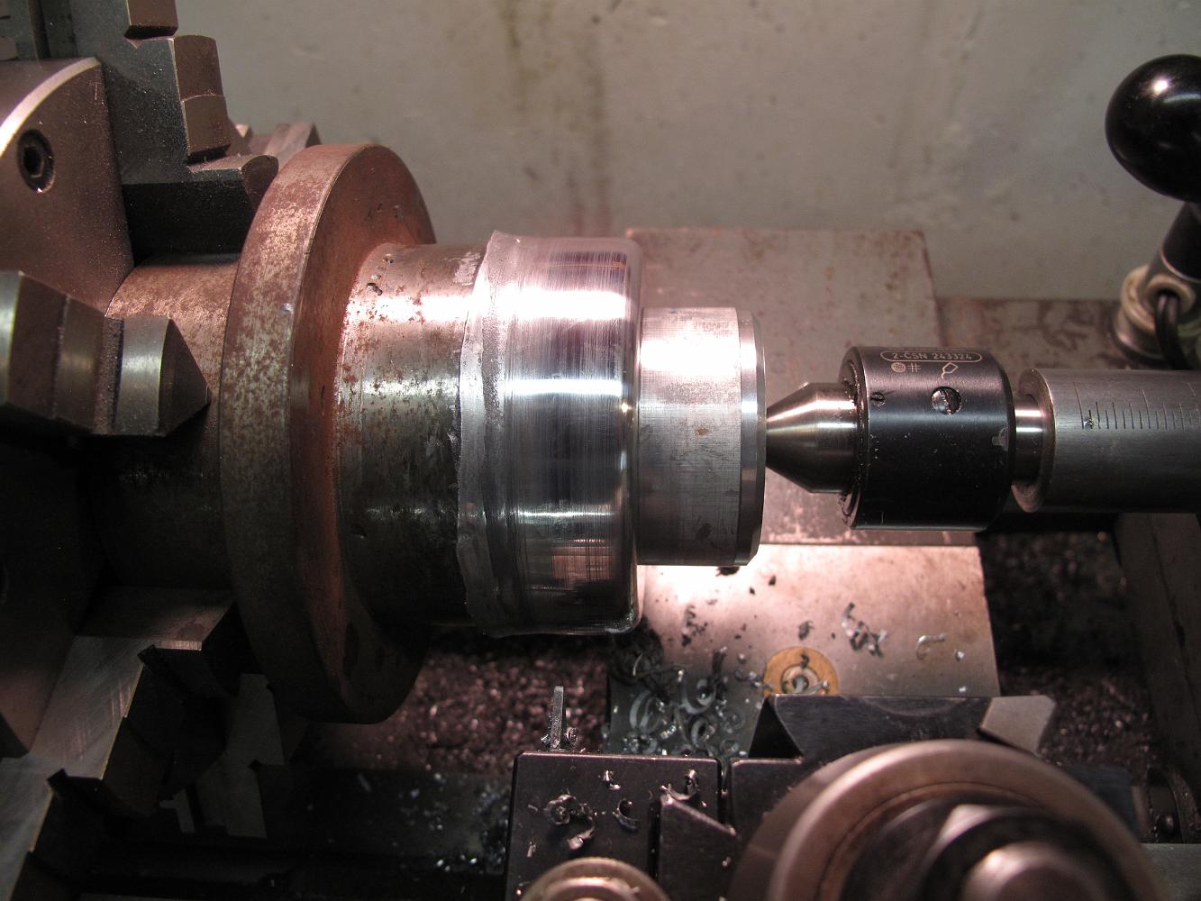
16-Nov-2014 It takes me several passes to make the finished cover.
16-Nov-2014 Spinning the covers in the lathe.
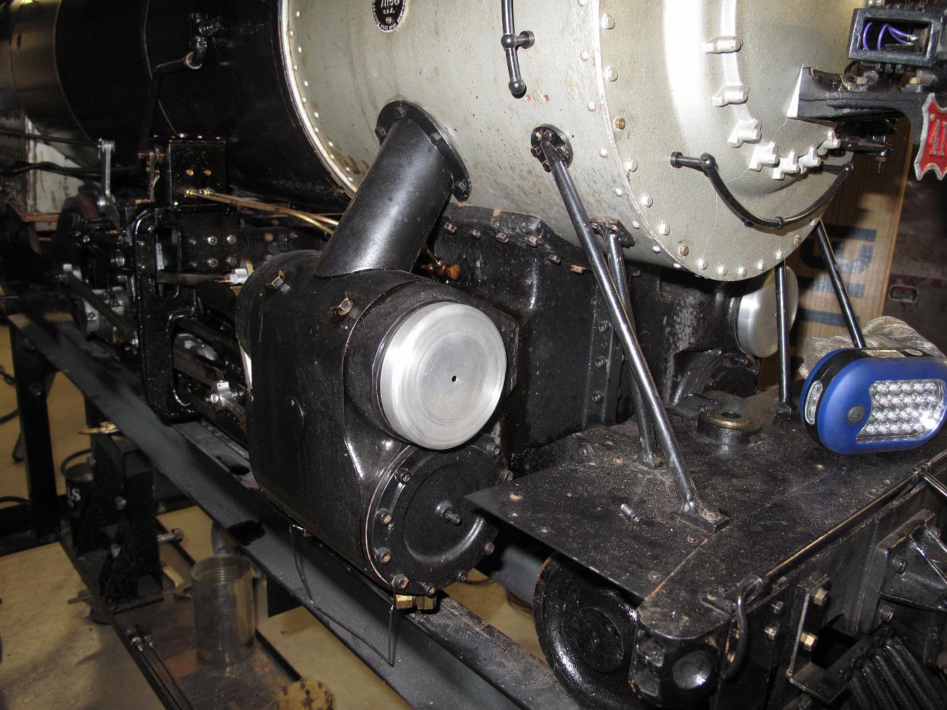
12-Nov-2014 - Five years after installing the cylinders on the frame, I get back around to making the cylinder covers.
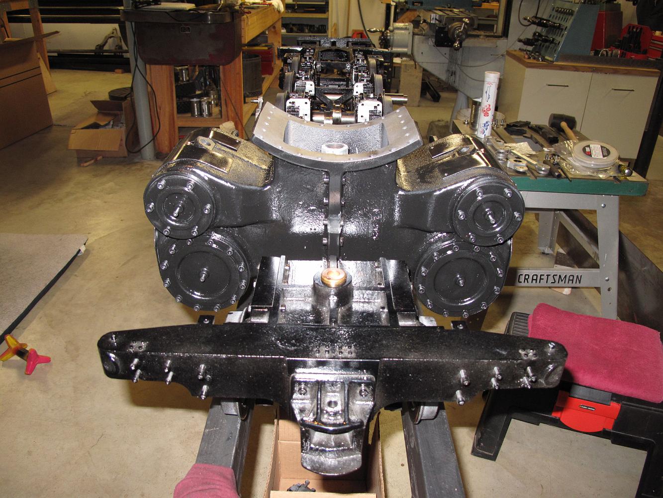
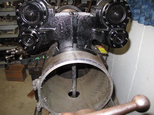
30-Sept-09 The cylinders are installed on the frame. Yea!
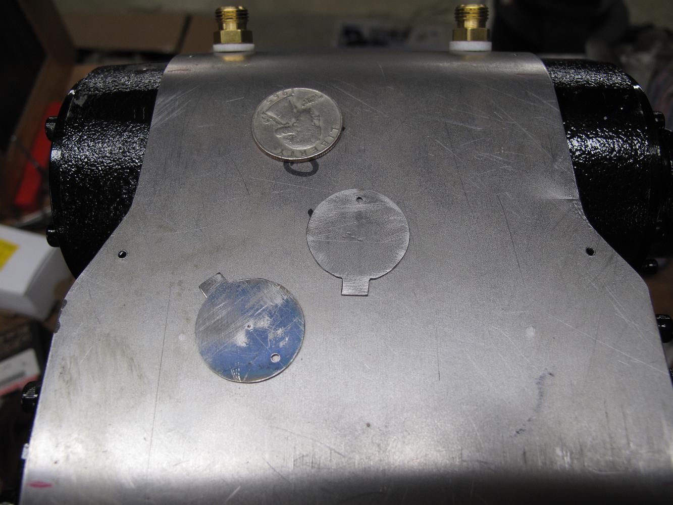
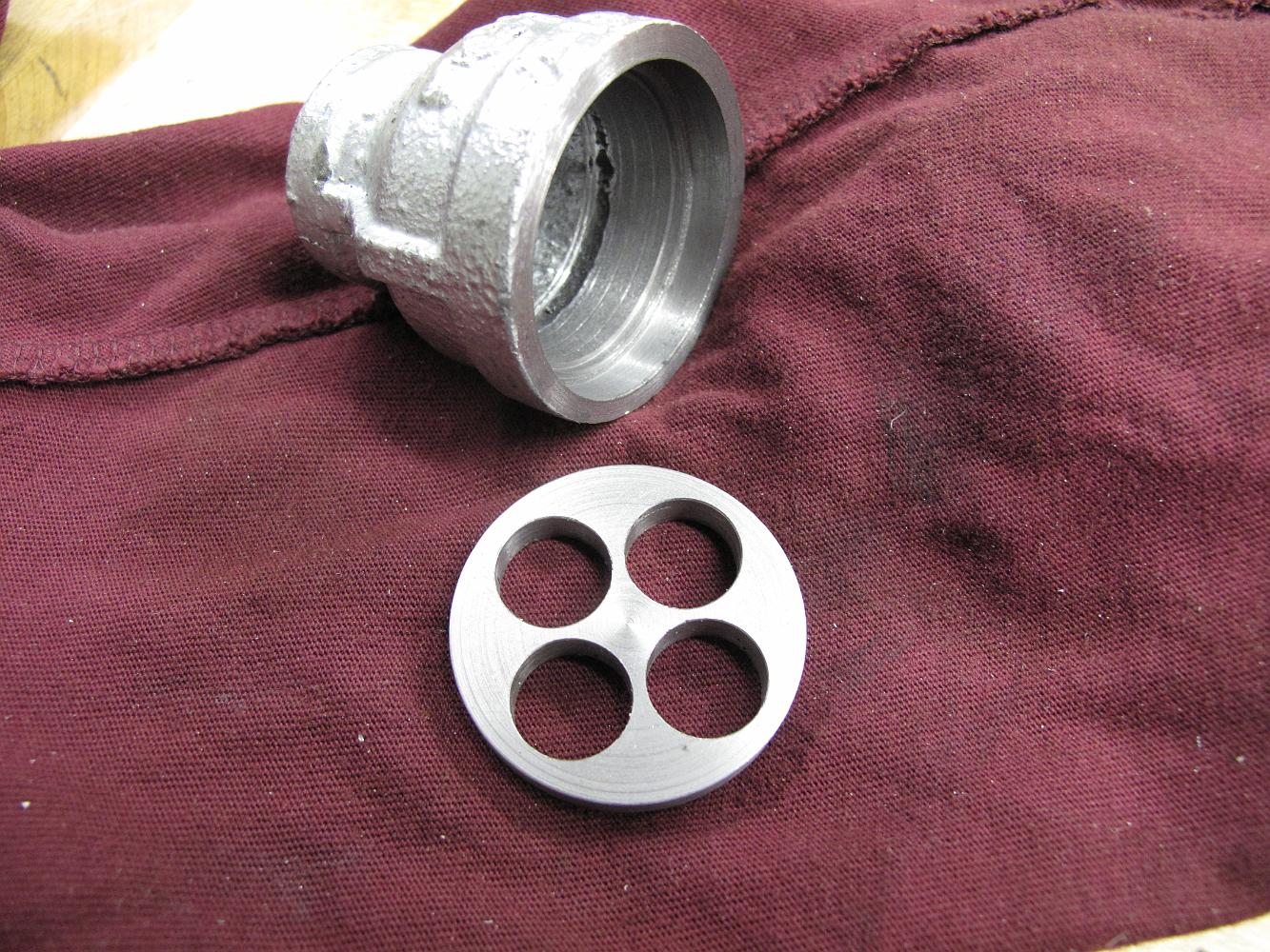
30-Aug-09 Frisco used round covers for the cylinder inspection ports on the jacketing I guestimated the size and made ones for each side.
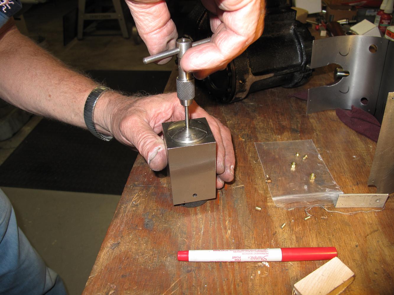
Tapping a 1/8-56 MTP fitting for the oil line. We used a collet to hang onto the tiny part.
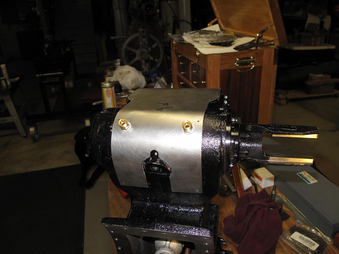
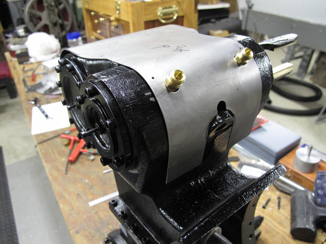
Test fitting the jacketing with the hold-down plugs.
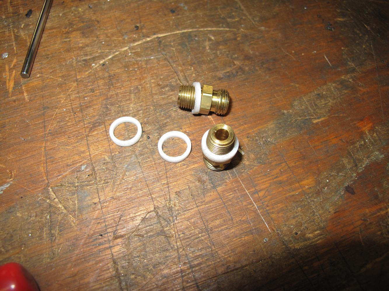
26-Aug-09 Temporary plugs with teflon plastic washers used to hold down and align the jacket to the cylinder assembly. They go in the valve inspection holes.
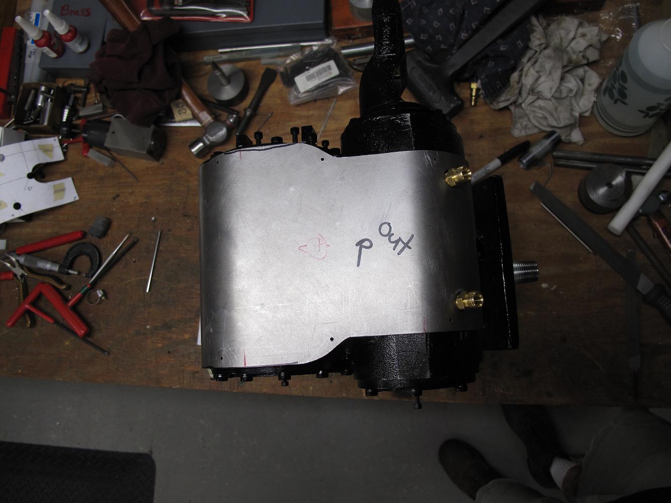
Since it is important to be able to see and use the inspection ports, we decide they should be the reference points on the jacketing. In fact, we will make some…
Another thing to do before mounting the cylinders on the frame is to mark out the cylinder wrapper screw holes. If we don't do it now, we will have to stand on…
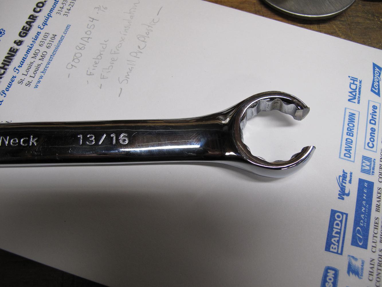
Another vexing problem solved: tighten the flare nut fittings. After purchasing a 13/16" crow's foot, 12-point, flare nut wrench of 3/8" sockets, we find there…
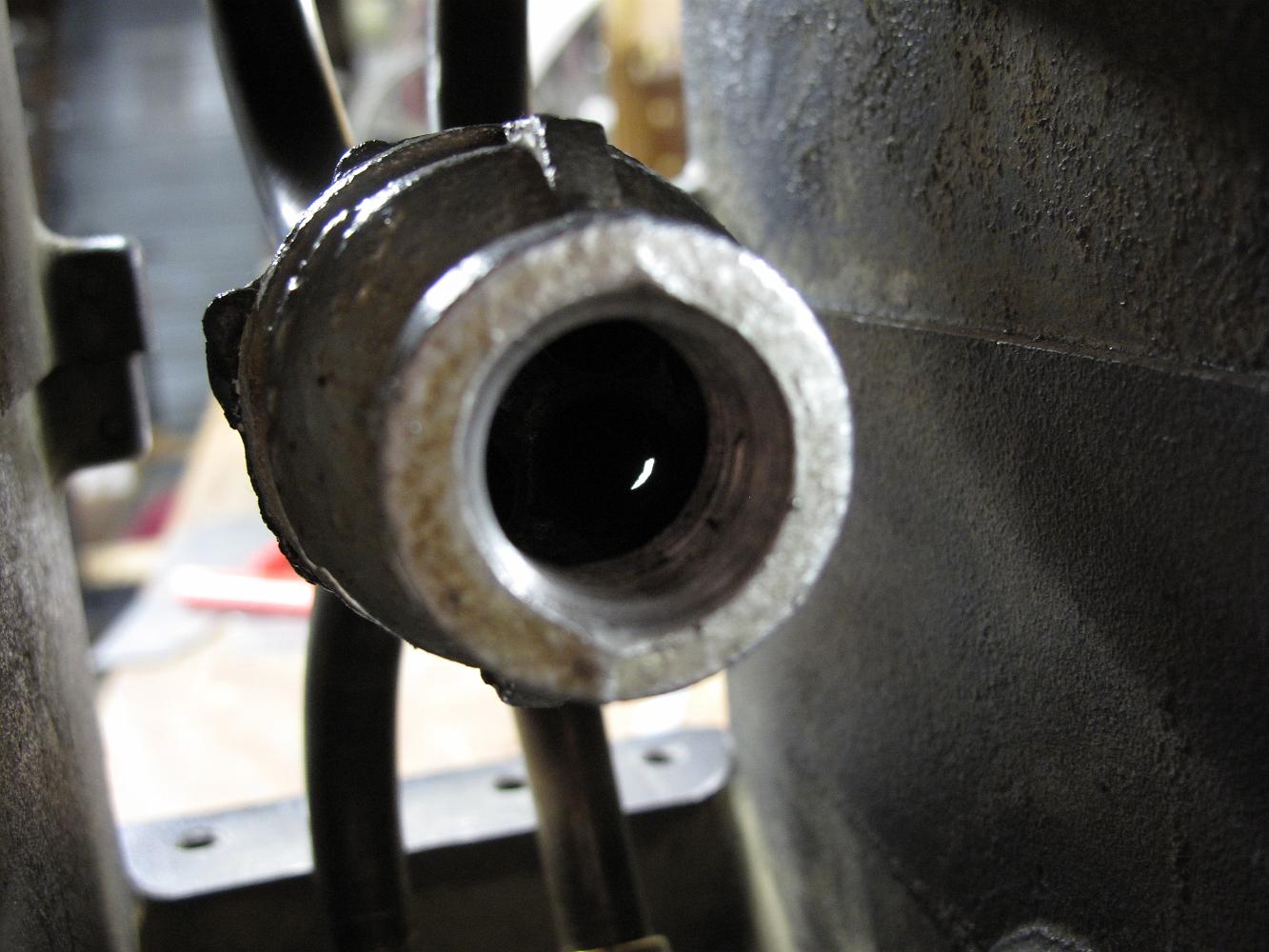
Proposed solution: Using a piece of brass pipe with fits the OD the the pipe, pre-silver solder the inside of the collar and silver solder them to pipes.
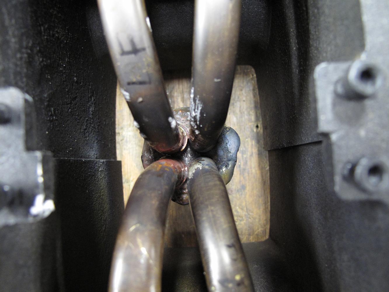
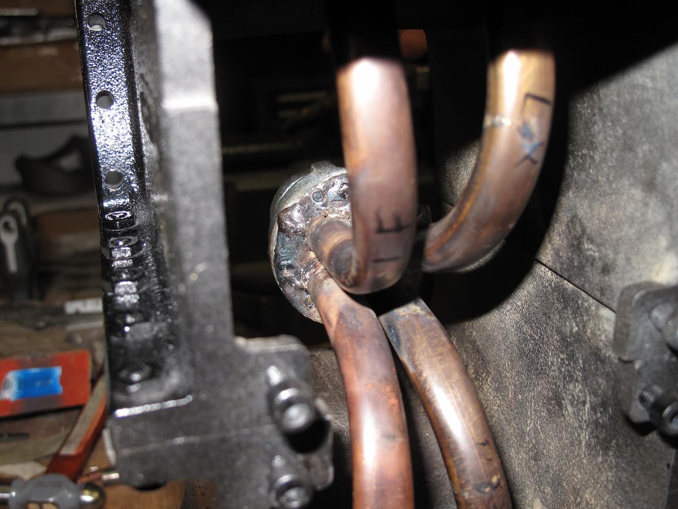
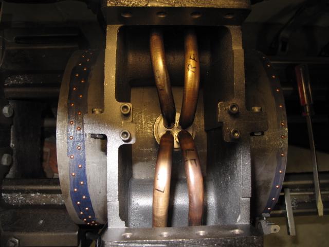
19-Aug-09 Shop night 4 on this manifold assembly and now we're patching holes in two of the brass tubes. We worked so hard to fabricate and fit them that I'm…
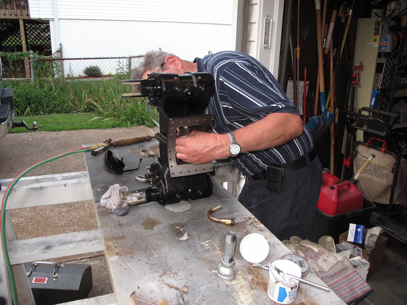
12-August-09 Inspection time at the End of night and shop night 3 on this one assembly. I can't believe how difficult this has turned out to be. But wait--Is…
A quick touch with a 3/32" 6013 GMAW rod and the plate is welded to the reducer. Problem was my auto-darkening helmet did not see enough sunshine today and…
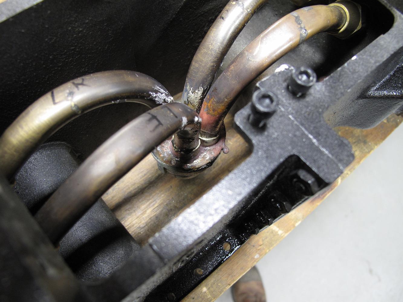
After silver soldering three of the pipes, the assembly has relaxed a bit and that troublesome fourth pipe has slipped out of the plate. We spend the next hour…
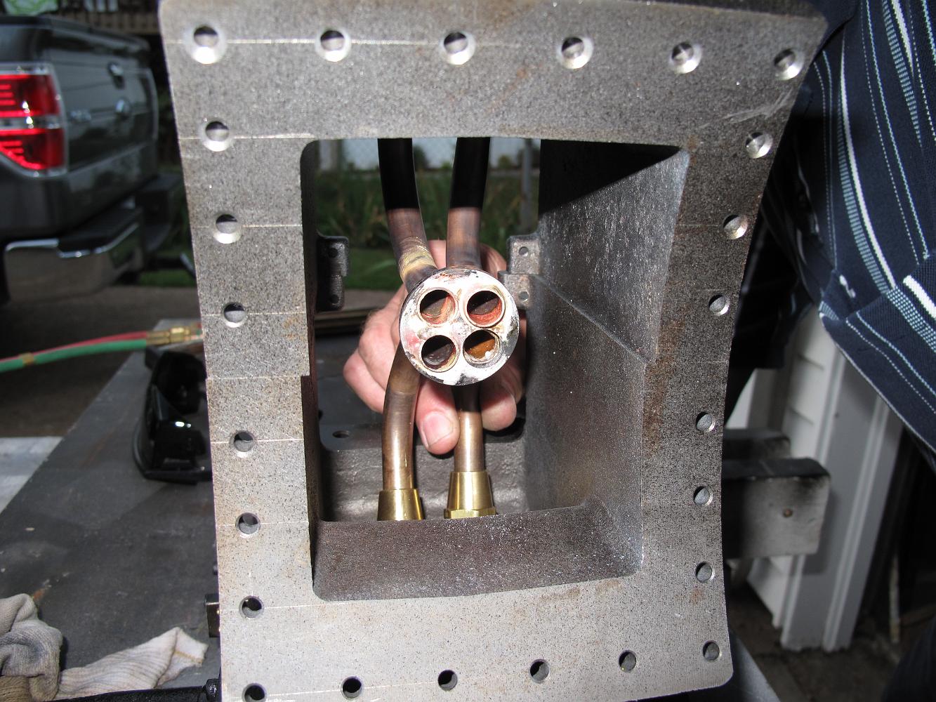
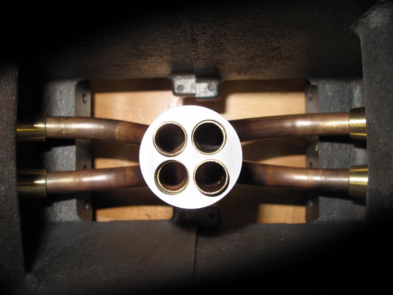
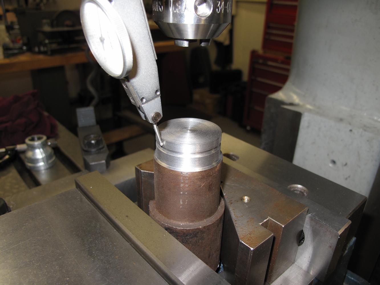
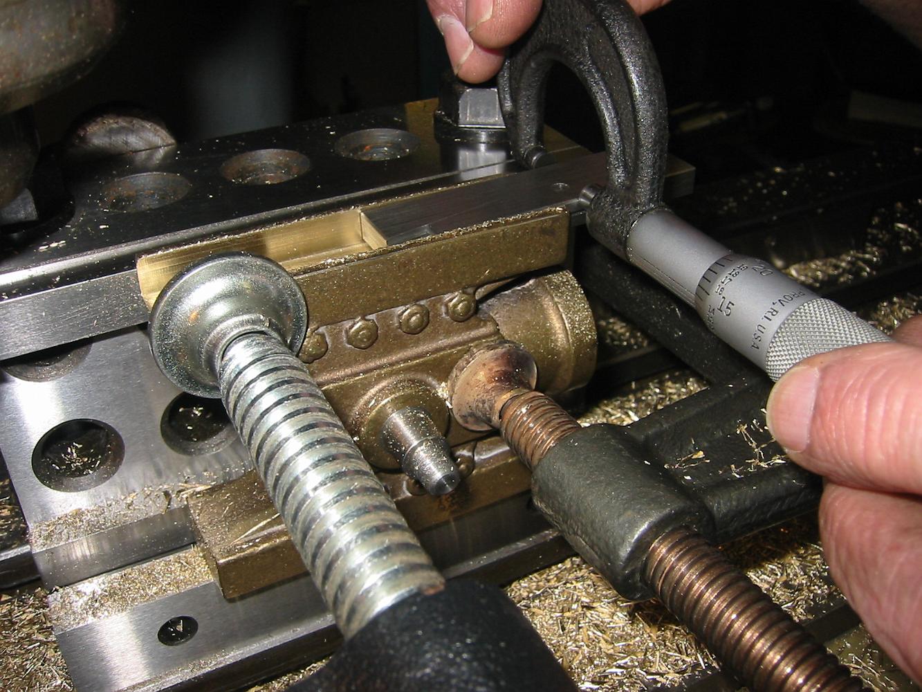
With all the pipes in the plate, we put the reducer on and check the assembly to see that it is still on center and in position. We measure the distance from…
12-Aug-09 We continue to fit and bend the pipes. By the end of the night, three look good in the plate, but the fourth just barely touches. More adjustments…
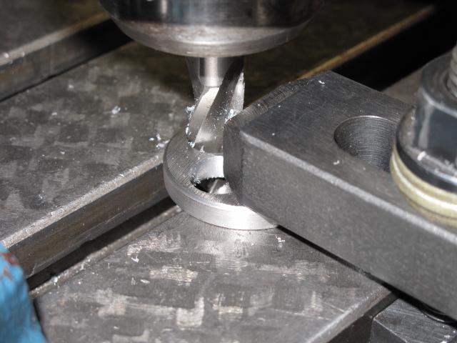
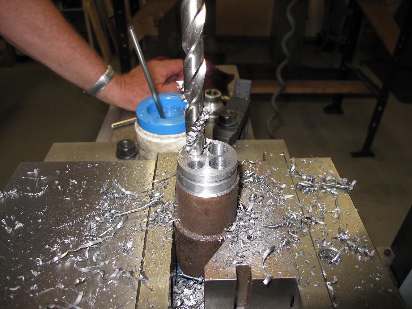
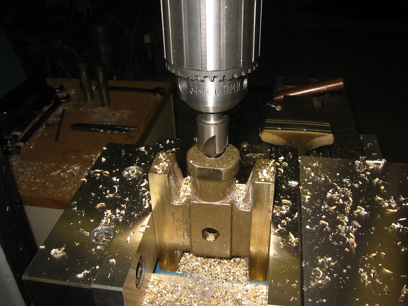
Using a 1/2" 1-degree tapered endmill to enlarge the holes. This should make it easier to assemble the piping.
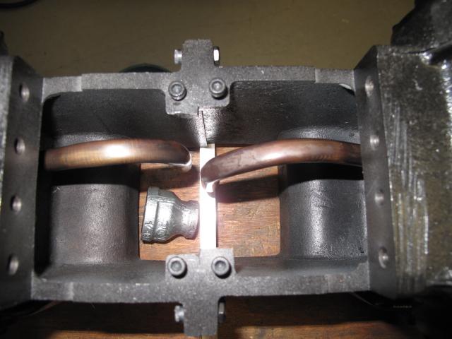
We continue to the assemble and alignment of the pipes inside the small space, while keeping the exhaust pipe centered in the hole.
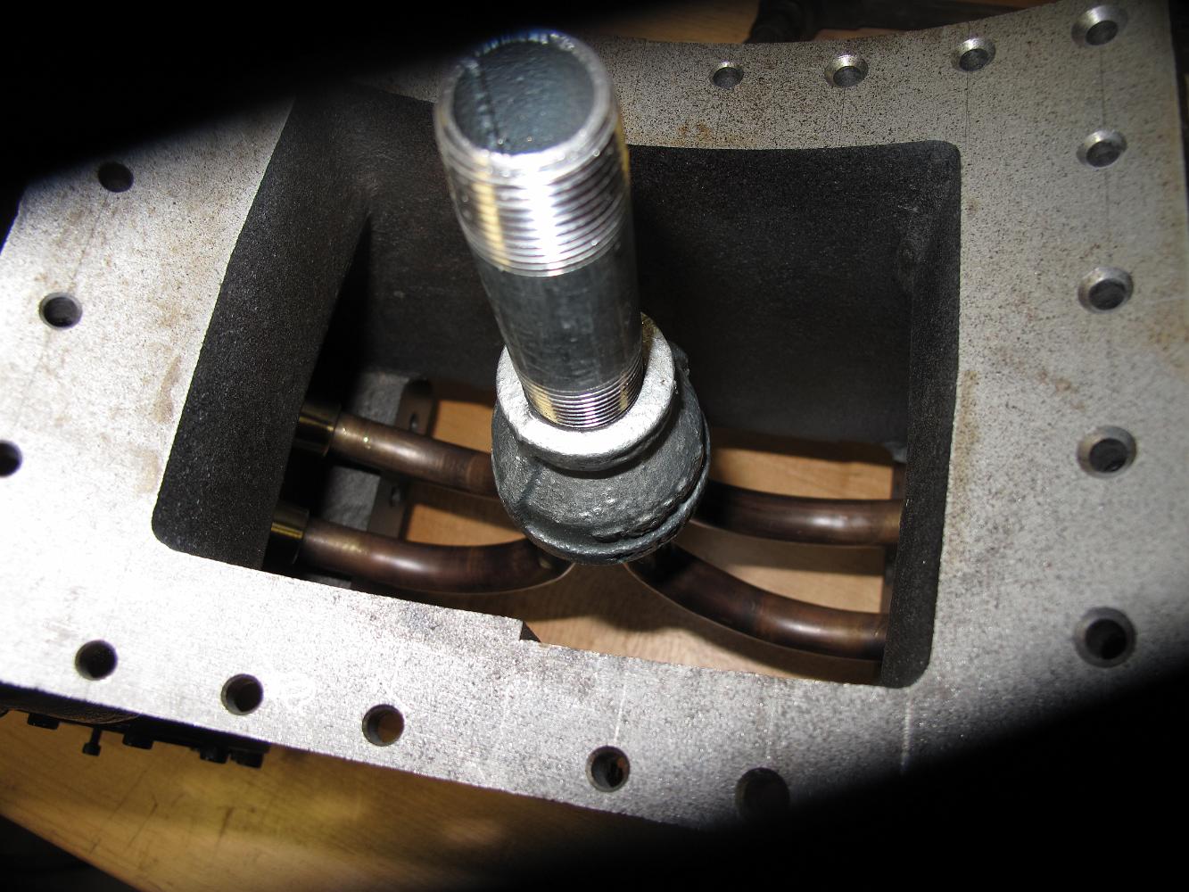
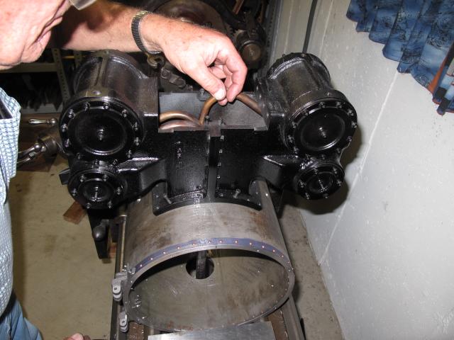
With the cylinders temporarily on the upside down smokebox, we use a piece of pipe to align the blast nozzle in the center of the smokebox. We put the assembly…
Checking the alignment of the bent tubes to the centerline. Some more adjusting is needed, and the s-bend to bring the pipes to the center is still needed. The…
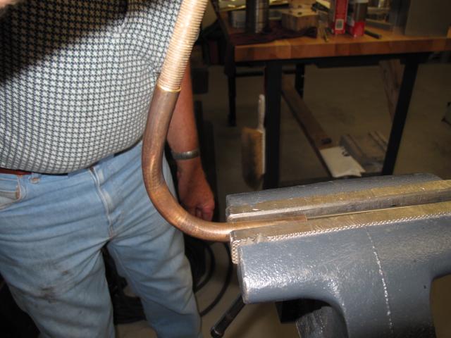
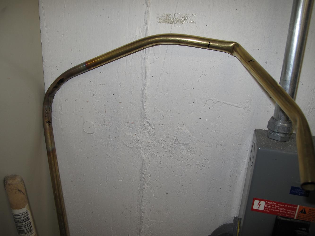
29-July-09 Putting the s-bend into the 1/2" brass pipe to bring the pipes from a 1.250" down to 9/16" centers. The s-bend is not shown on the print.
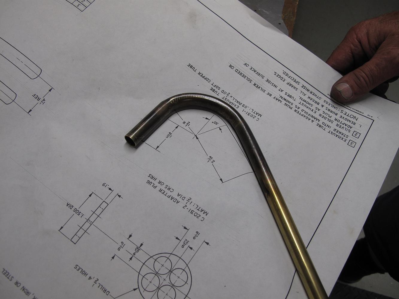
20-July-09 Checking the 1/2" brass pipe bend against the drawing. Lacking a proper pipe bending machine to put the 120 degree bend in, we ended up annealing the…
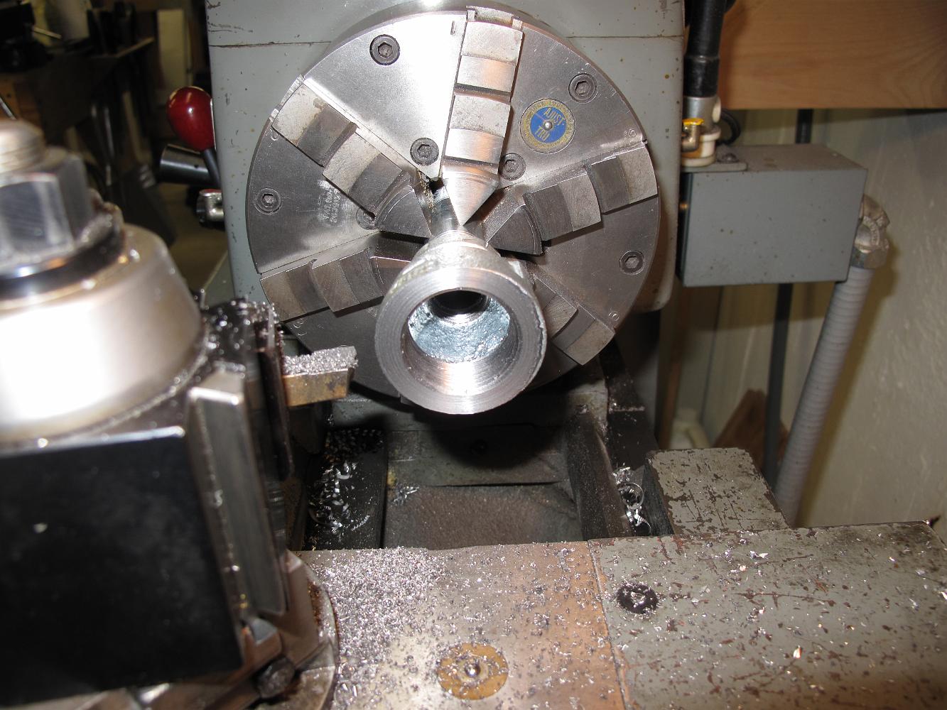
Drilling 1/2" holes in the adapter plate. After this step, the stock was put back in the lathe and using a parting tool, two plates were made from this stock.
12-July-09 An unsuccessful attempt to bend hard drawn brass tubing for the exhaust manifold. We even tried heating it a bit but it still kinked. Found out later…
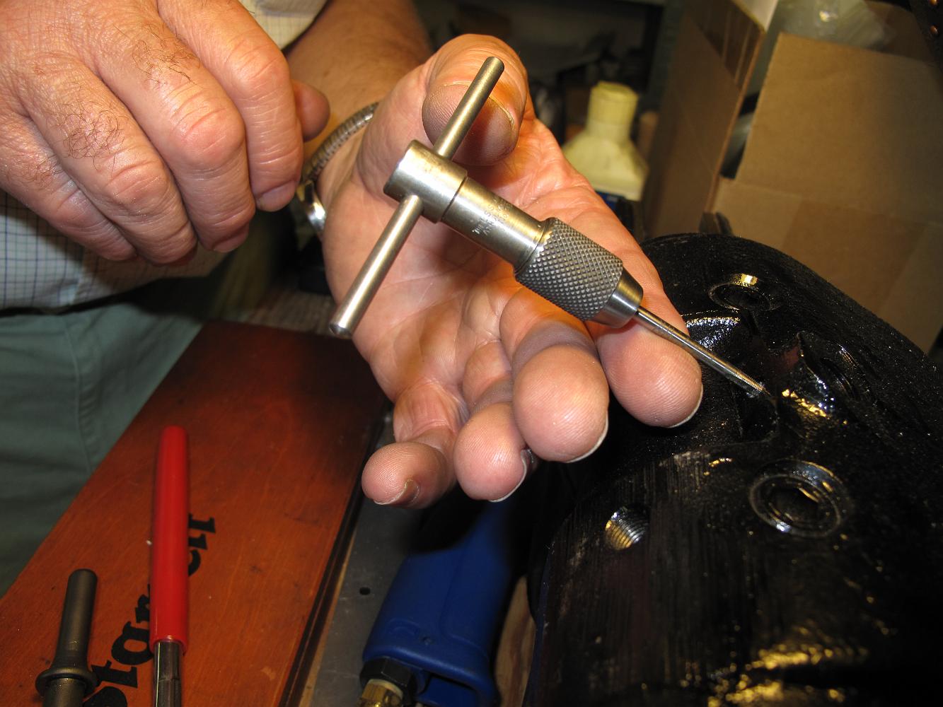
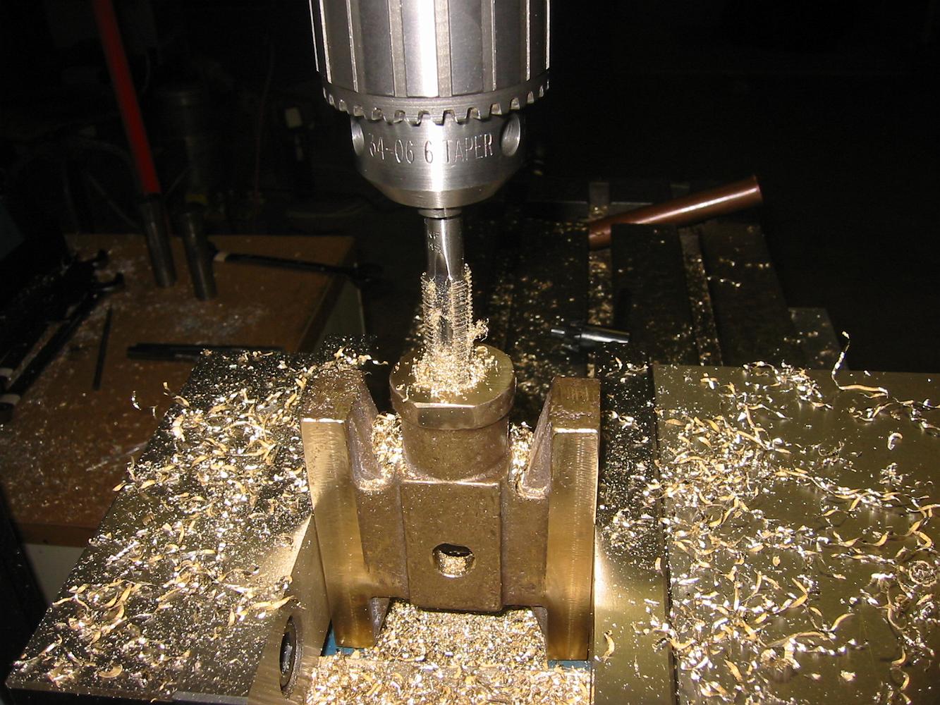
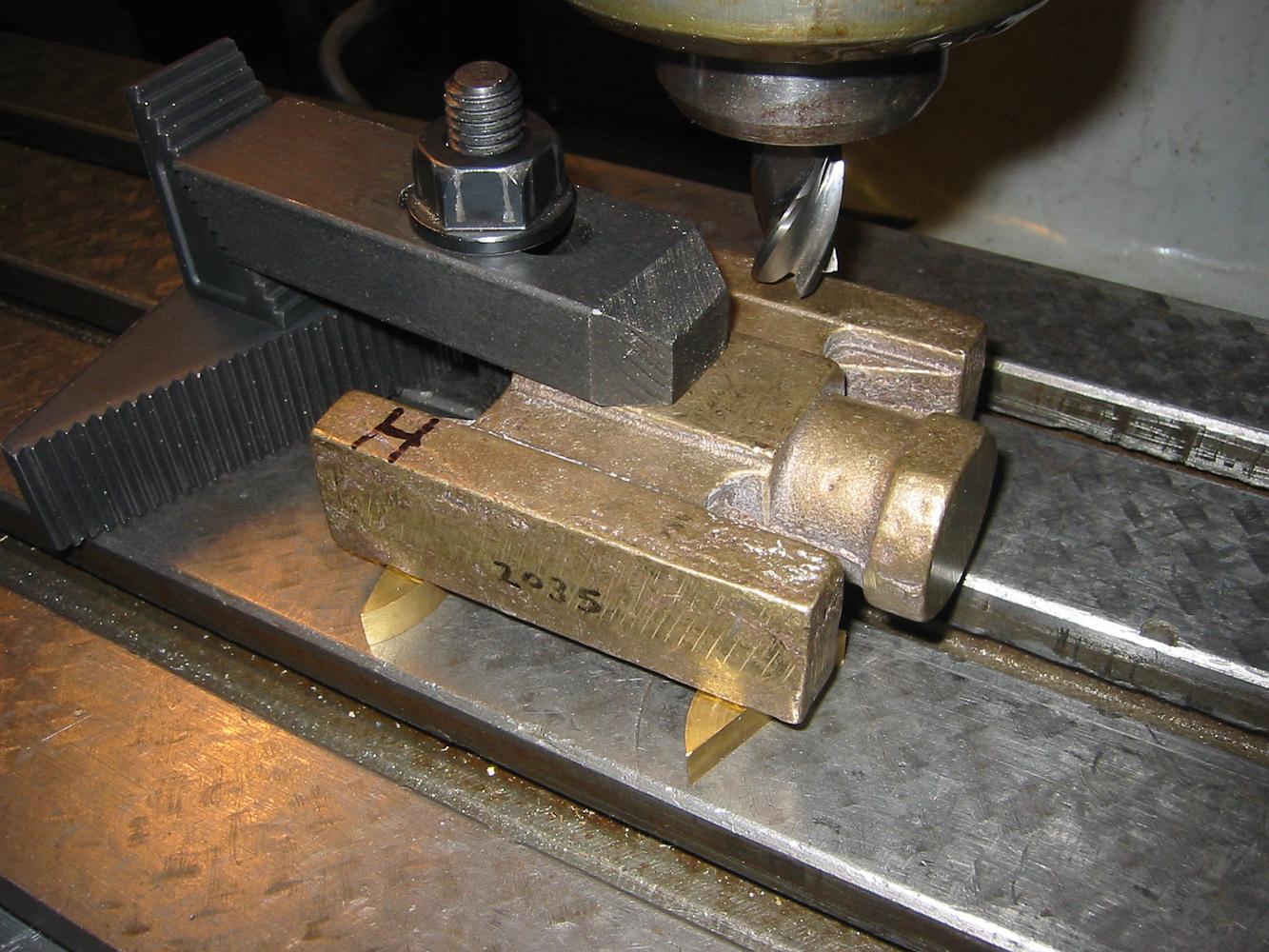
24-June-09 With some trepidation, we hand tap the 2-56 threaded oil lubrication hole. It turned out to be no problem, the cast iron cylinder material cut…
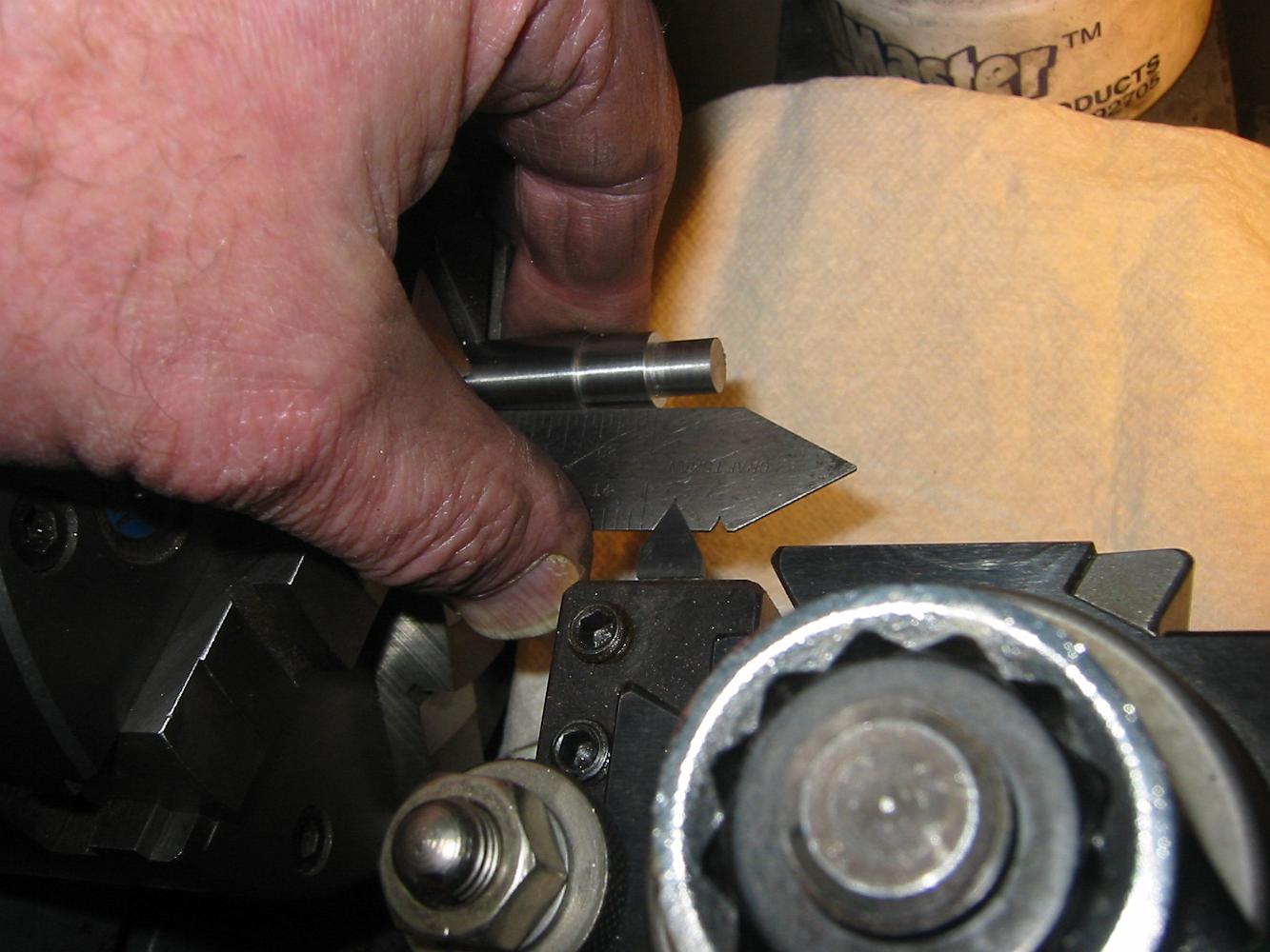
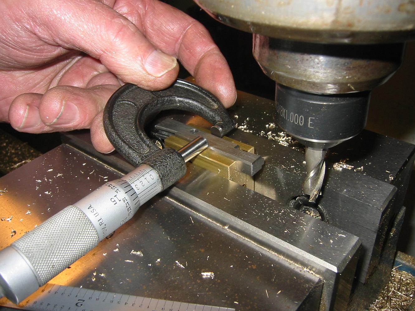
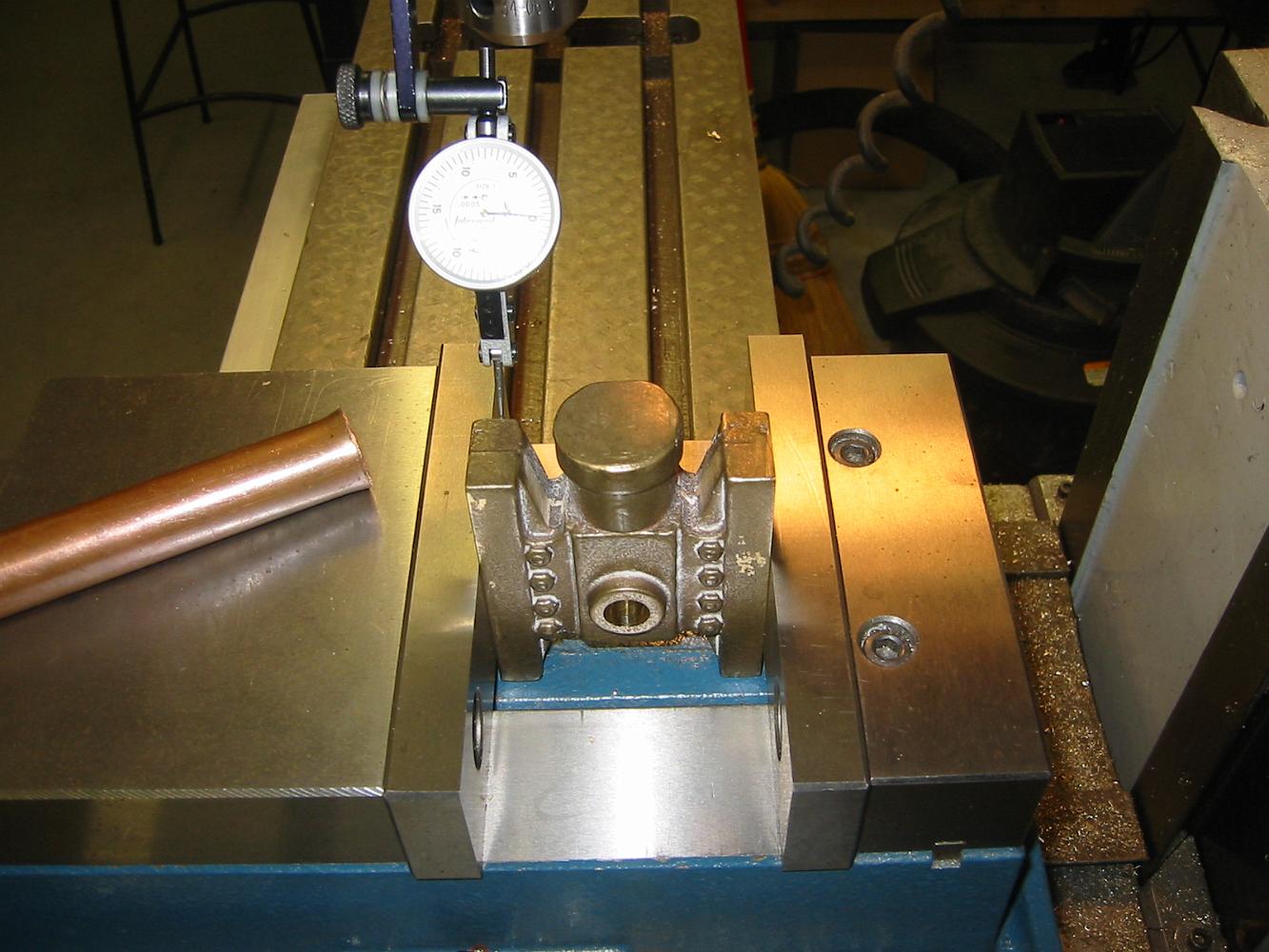
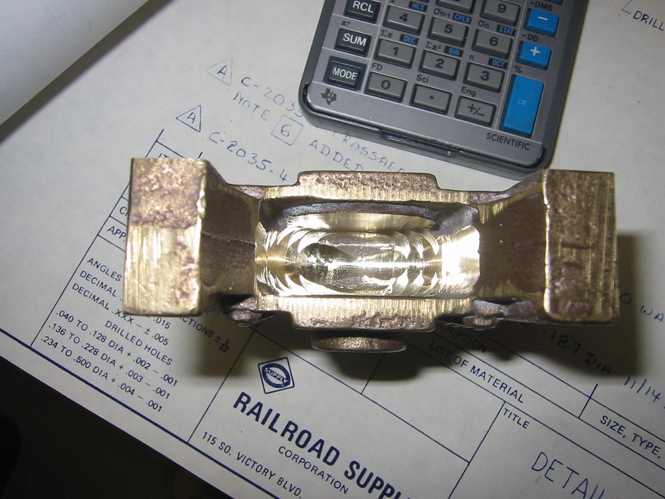
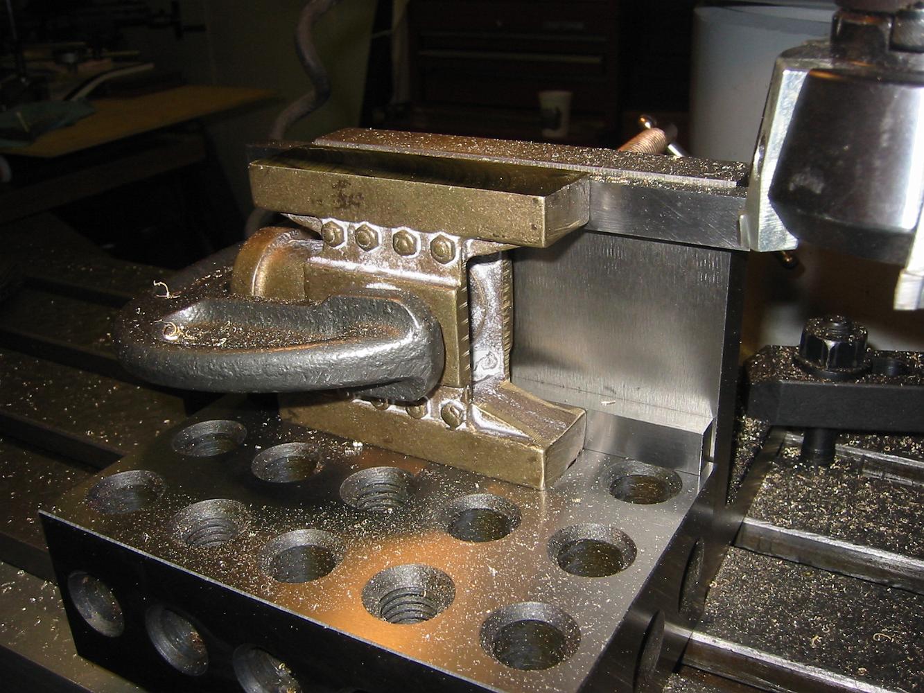
17-Jan-07 Using a split adjustable parallel to measure the width of the crosshead shoe. This method is more accurate than using a vernier.
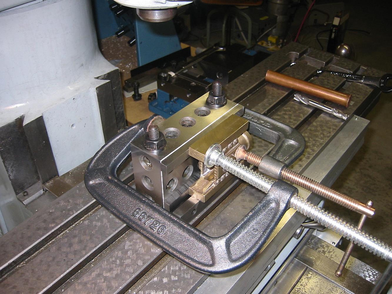
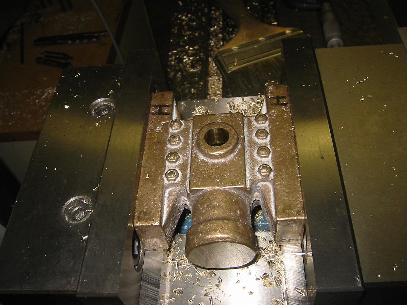
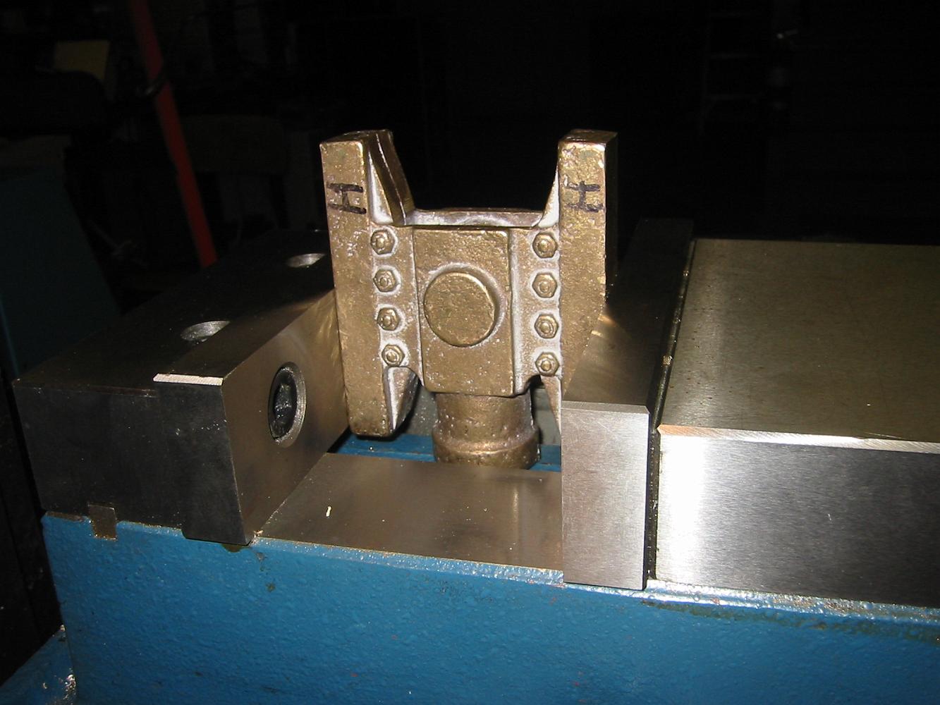
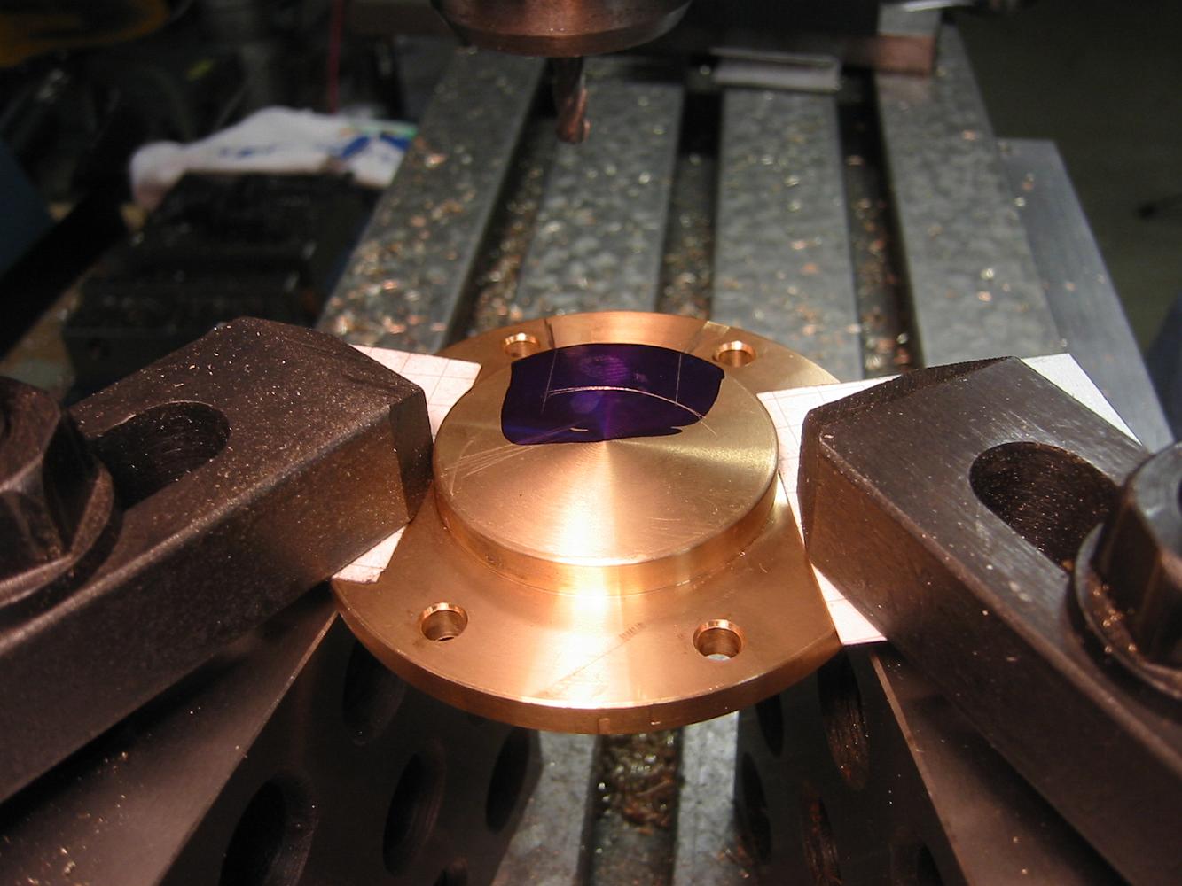
17-Jan-07 Using a 2-4-6 block bolted to the table, the crosshead is clamped down for shoe machining. We would have used an angle plate, but I didn't have one…
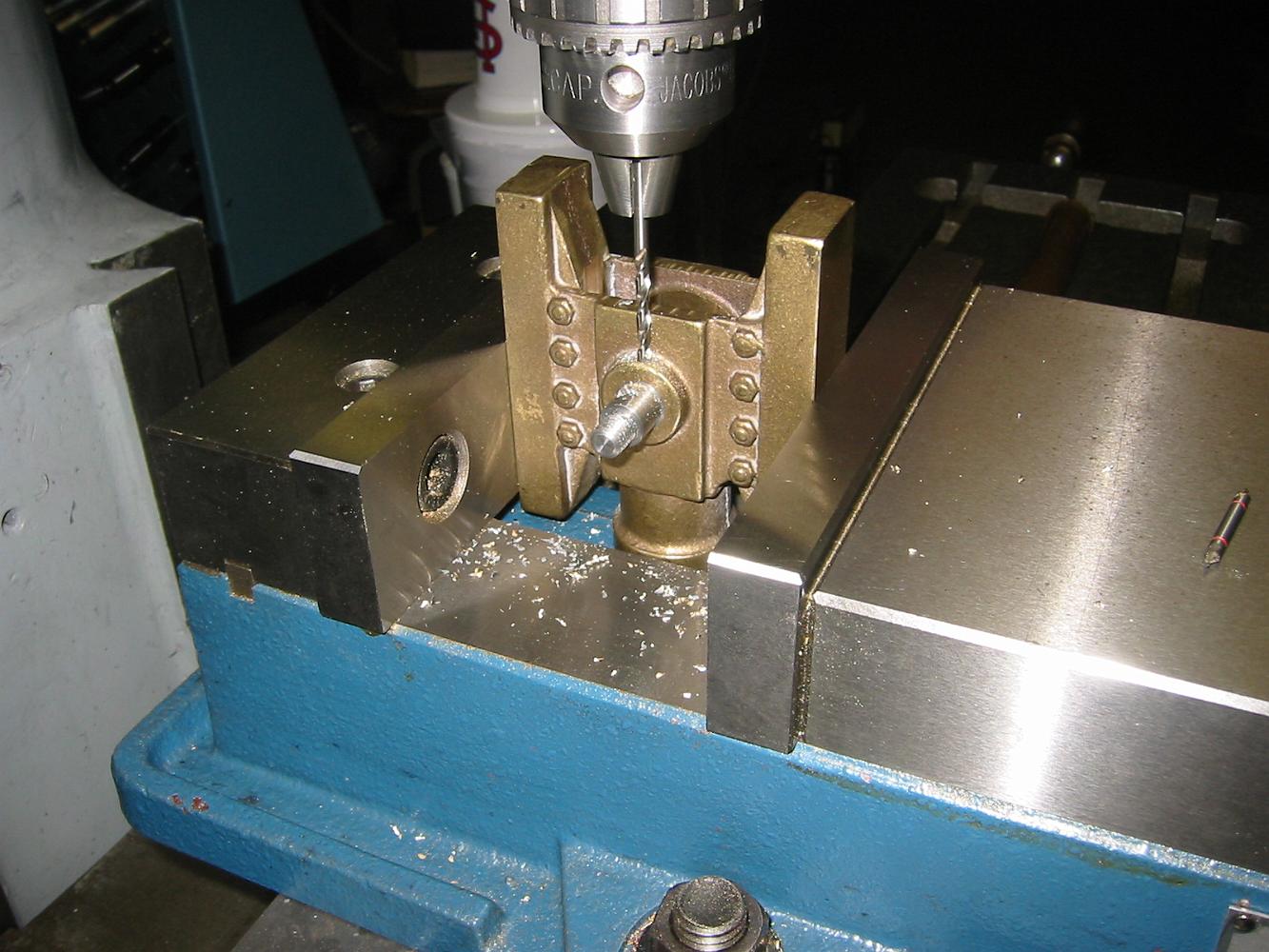
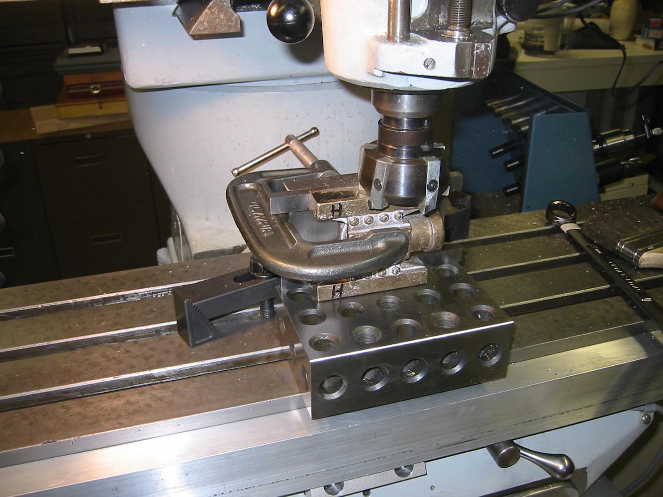
17-Jan-07 Drilling the crosshead wrist pin keeper. We used a very small, long spotting drill to get the hole started on the edge of the fileted boss.
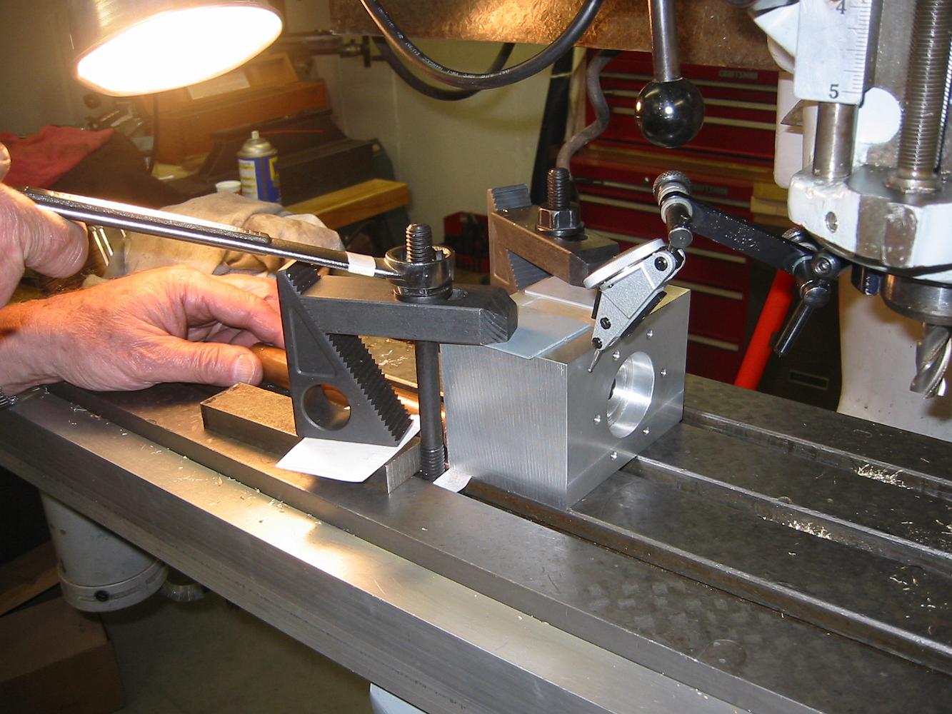
10-Jan-07 How to align the threading tool using a 'fishscale'. It helps if you put a white paper in the background and put a light on it so you can see the…
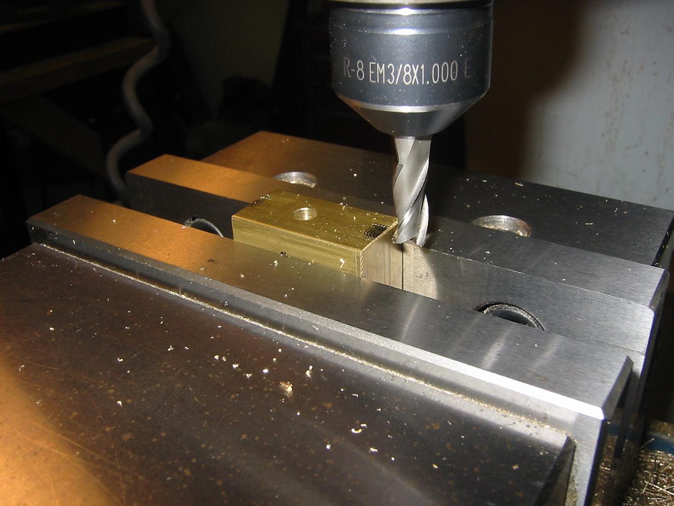
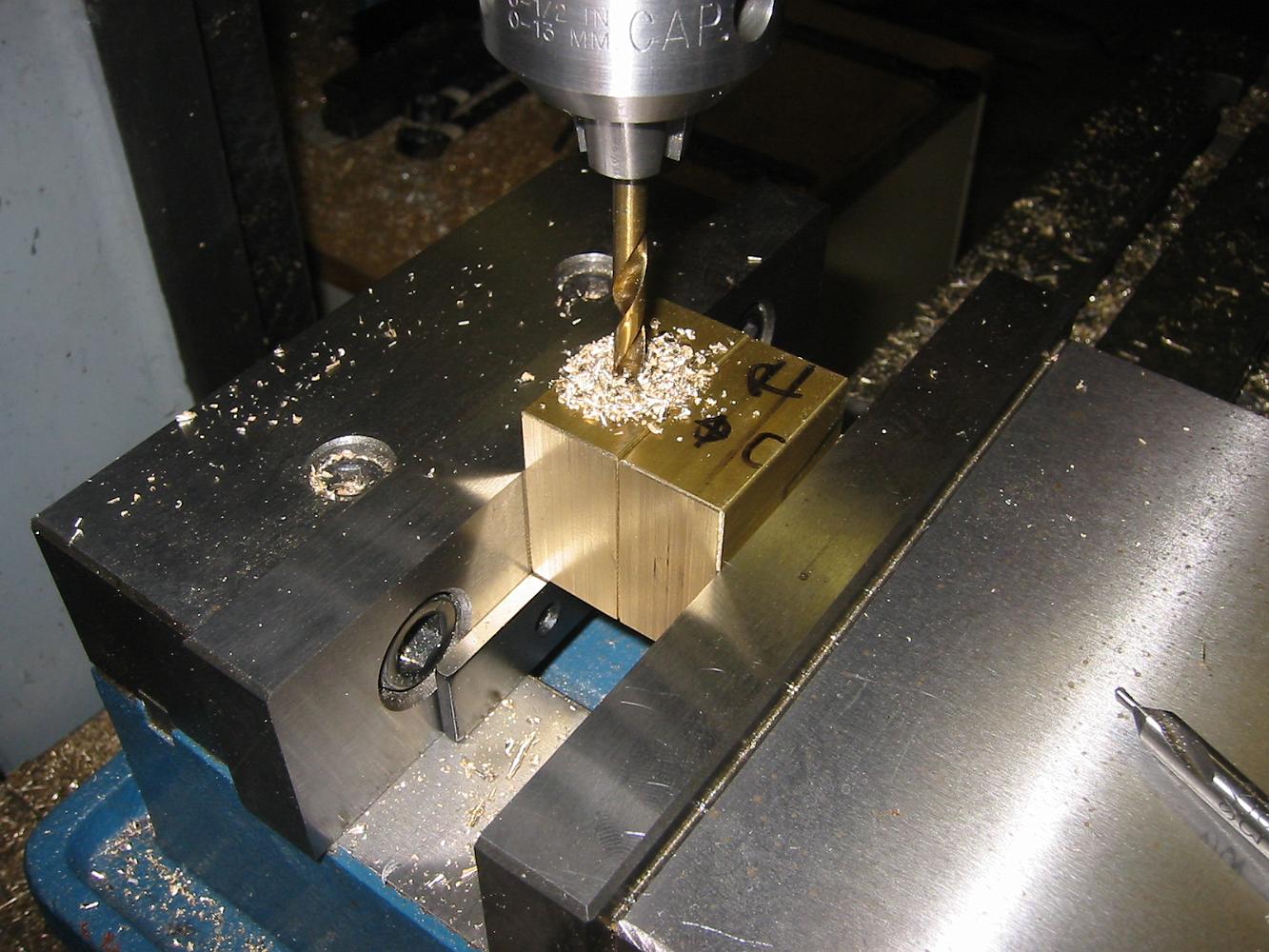
6-Dec-06 After a quick trip to the Metals Supermarket in town earlier this week for the .750 x 1.500 brass stock, we start on the Valve Crossheads. After…
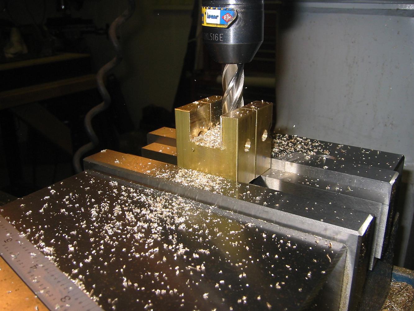
6-Dec-06 Next step: Tap (under power) the 1/2-24 TPI hole. After this, face the top of the crosshead. On the other crosshead, we will face it first, then drill…
6-Dec-06 Putting a chamfer on the drilled hole for tapping. Shown is the backside of the piston crosshead, which is the machined and reference surface.
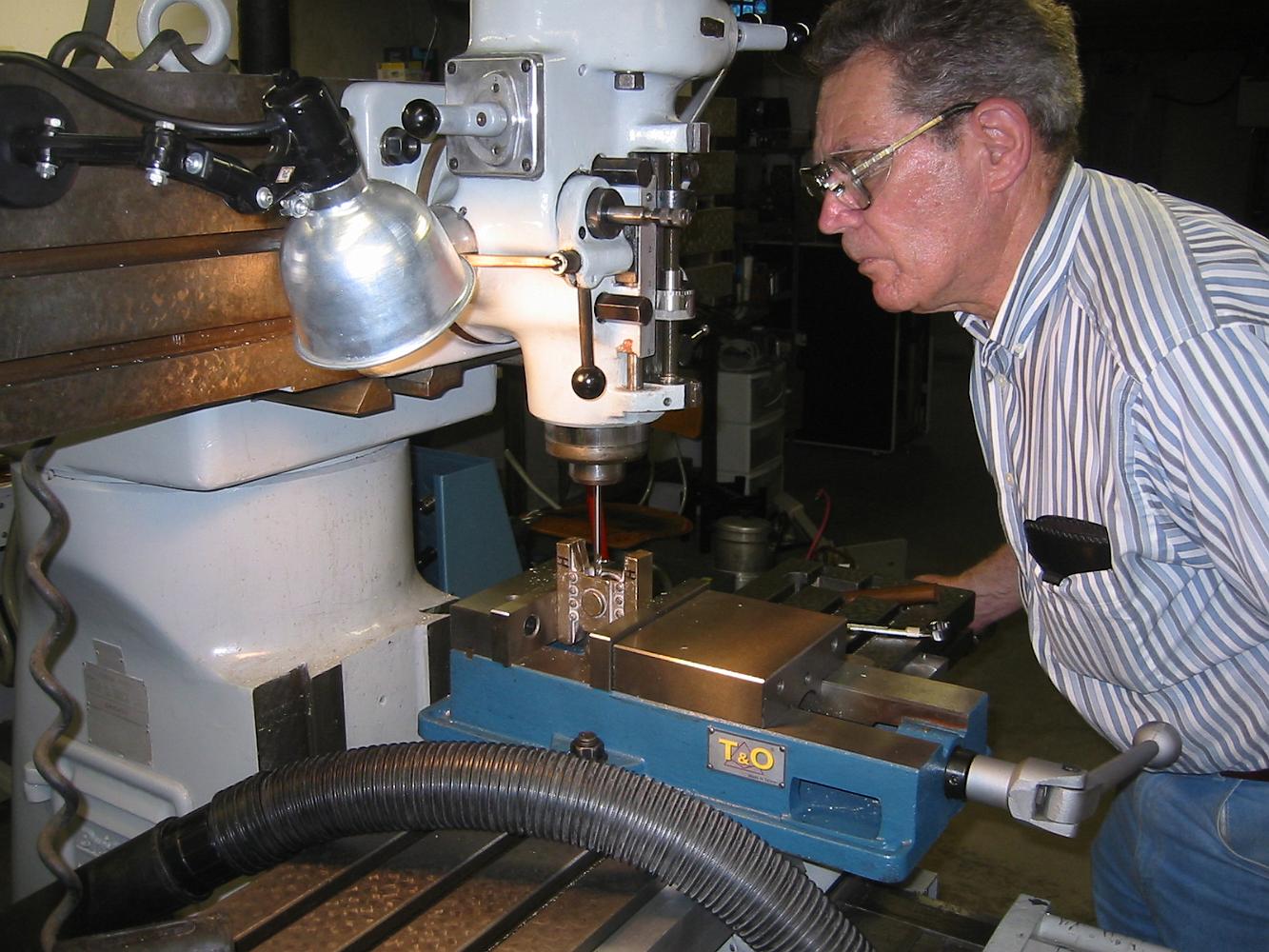
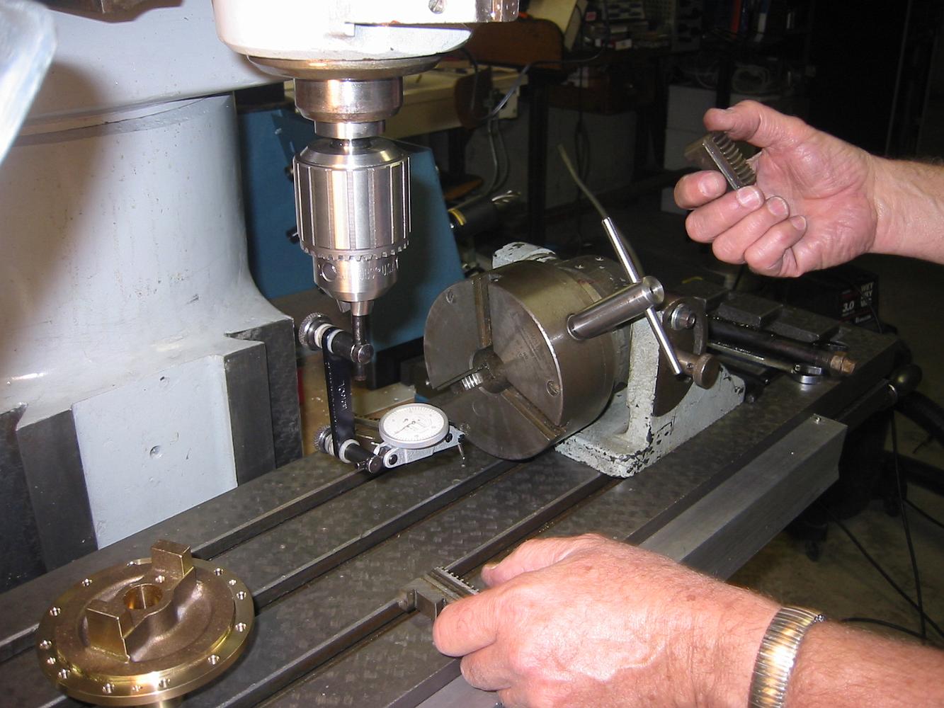
6-Dec-06 Next step: face, drill and tap the hole for the piston rod. Here Bill is indicating the piston crosshead to assure it is vertical.
29-Nov-06 The results work, but the finish is a bit 'steppy' where we had to hand radius the bottom.
29-Nov-06 An acceptable, but not ideal setup: a very long, and thus springy/chattery ball cutter to finish the casting interior.
22-Nov-06 The set up is the best we could do with my limited shop equipment: a 2-4-6 block, parallels, angle plate and 6" c-clamp.
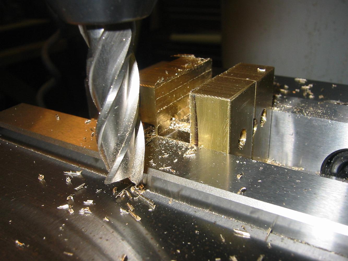
22-Nov-06 Rough cutting a machined surface on the top and bottom crosshead shoes to be used in future setups.
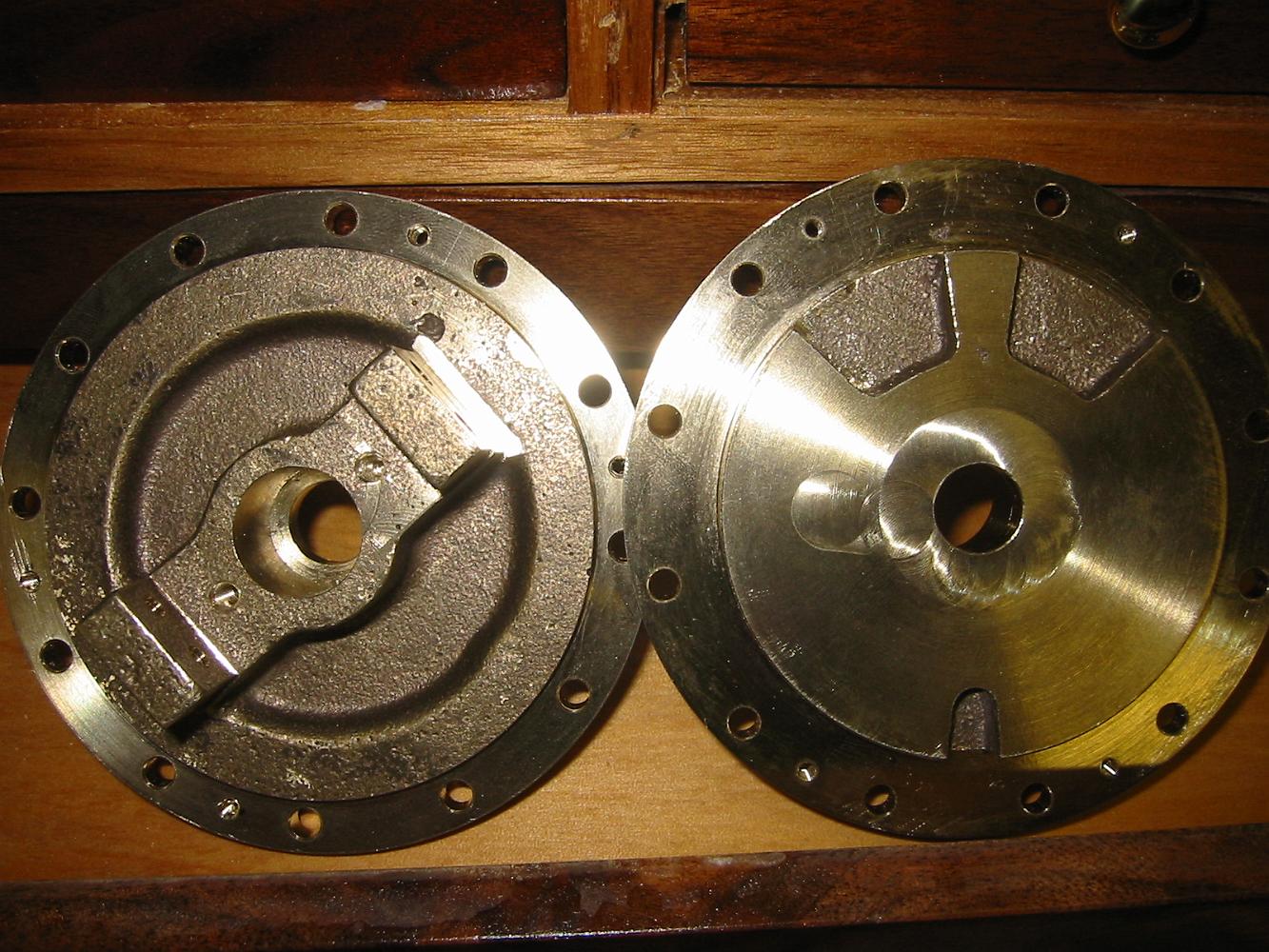
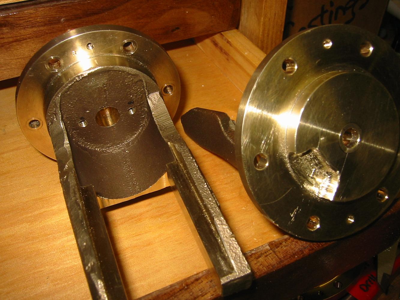
15-Nov-06 We also opened up the front valve covers also by This was not call for in the prints, but similar to the piston covers.
15-Nov-06 We decided to 'open up' the valve ports a little bit and mill some exhaust steam passages. This was not call for in the prints, but similar to the…
15-Nov-06 One of the last steps is to drill and tap the packing gland holes. It's a close one for the spotting drill and tap -- check out the clearance between…
26-Oct-06 A one hour setback: the Valve Crosshead guides were machining with a taper. Investigation found the block was slightly tilted front to back. Much…
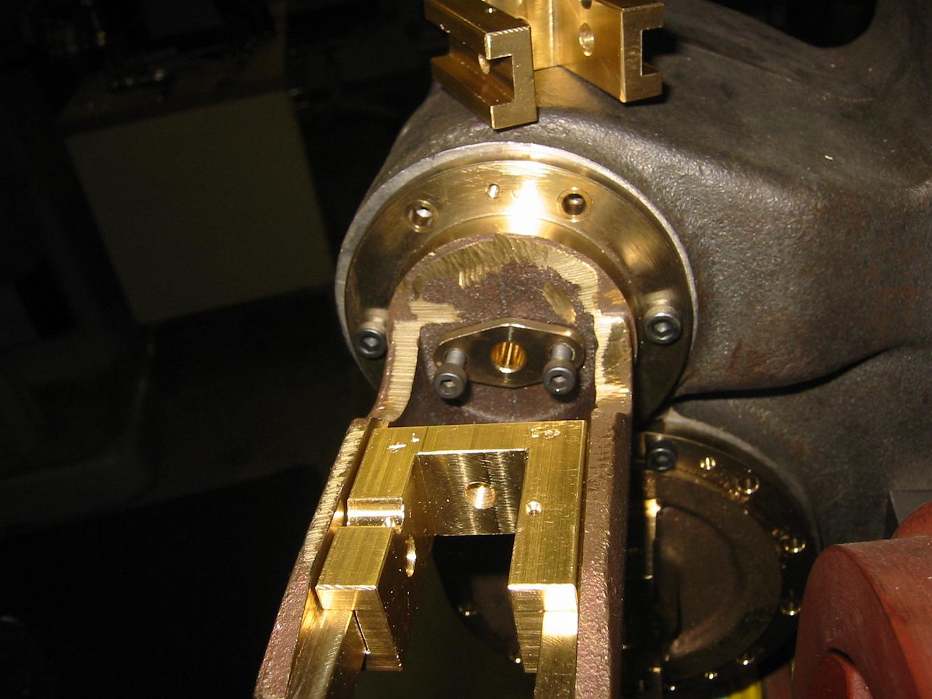
26-Oct-06 The crosshead jaws machined to width. Next, machine the step in them to make the crosshead guides.
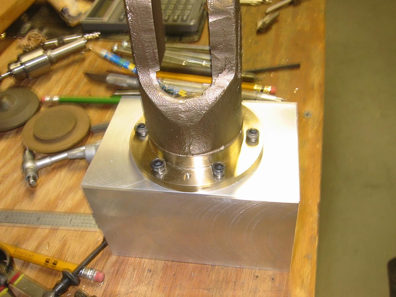
14-Oct-06 The completed Valve Crosshead holding fixture (the aluminum block) with the crosshead bolted on and ready for use. Next time, machining the crosshead…
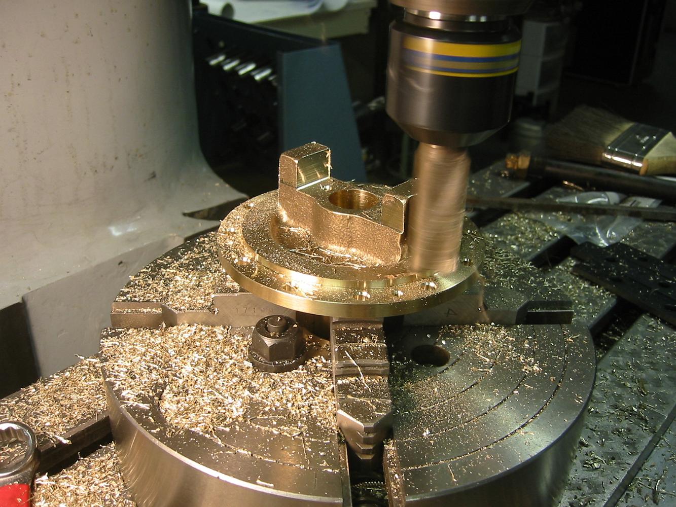
14-Oct-06 Kids, don't try this at home: Lacking a boring head which could go out to 1.750", we put a small fly cutter in the boring head and completed the…
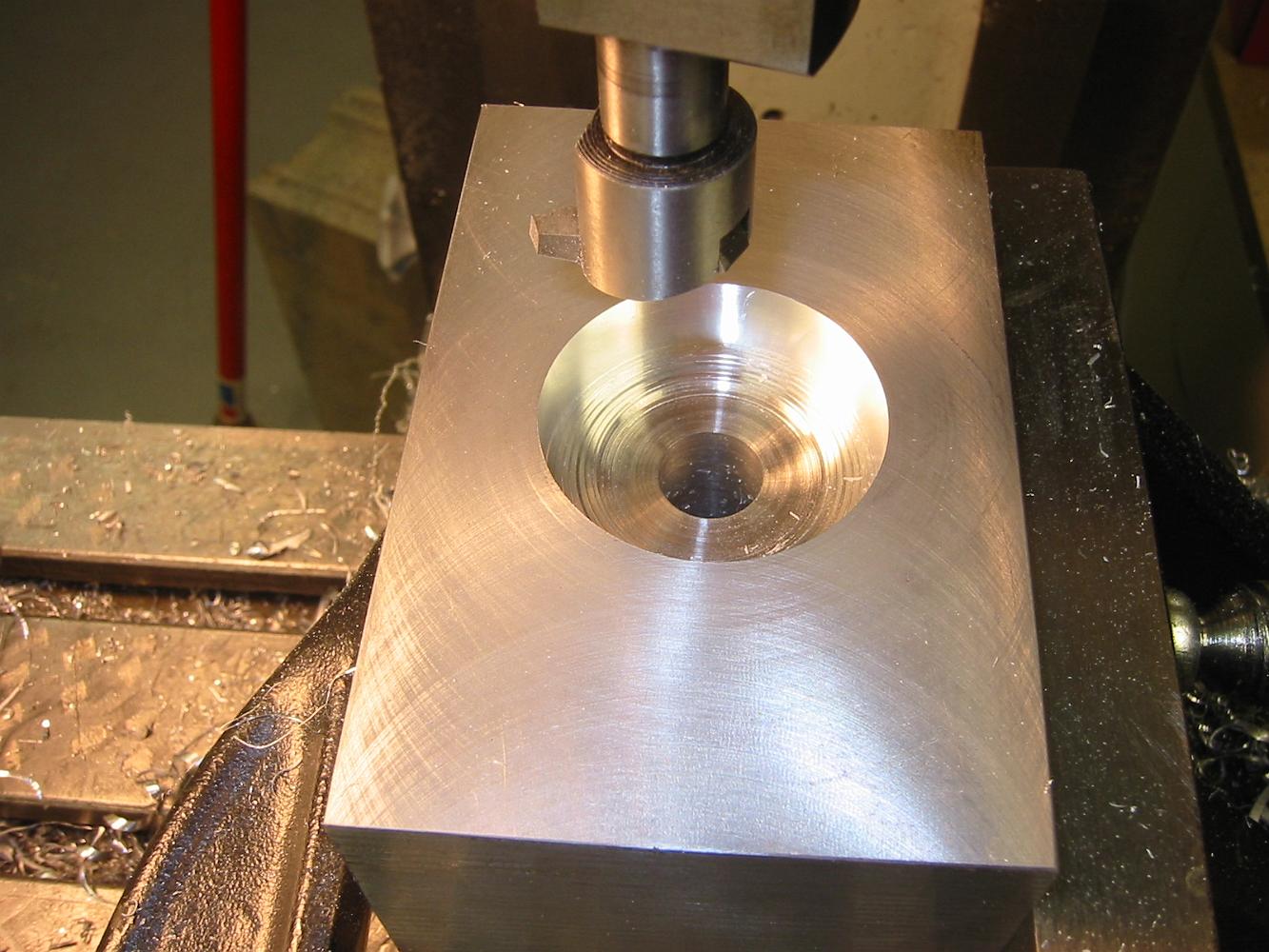
14-Oct-06 After fly cutting the top square to the angle plate, we begin to bore out a hole to bolt the Valve crosshead guide to.
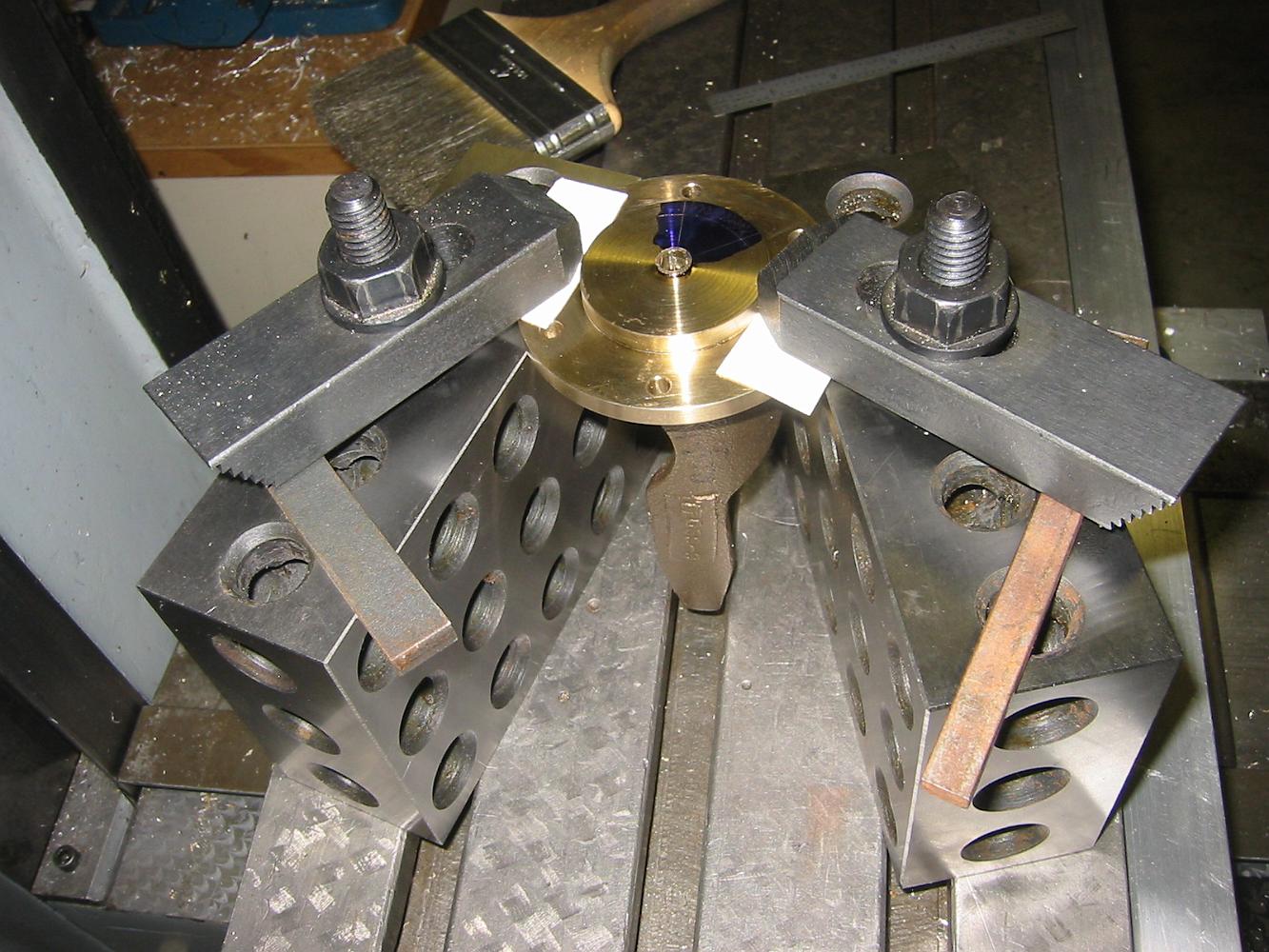
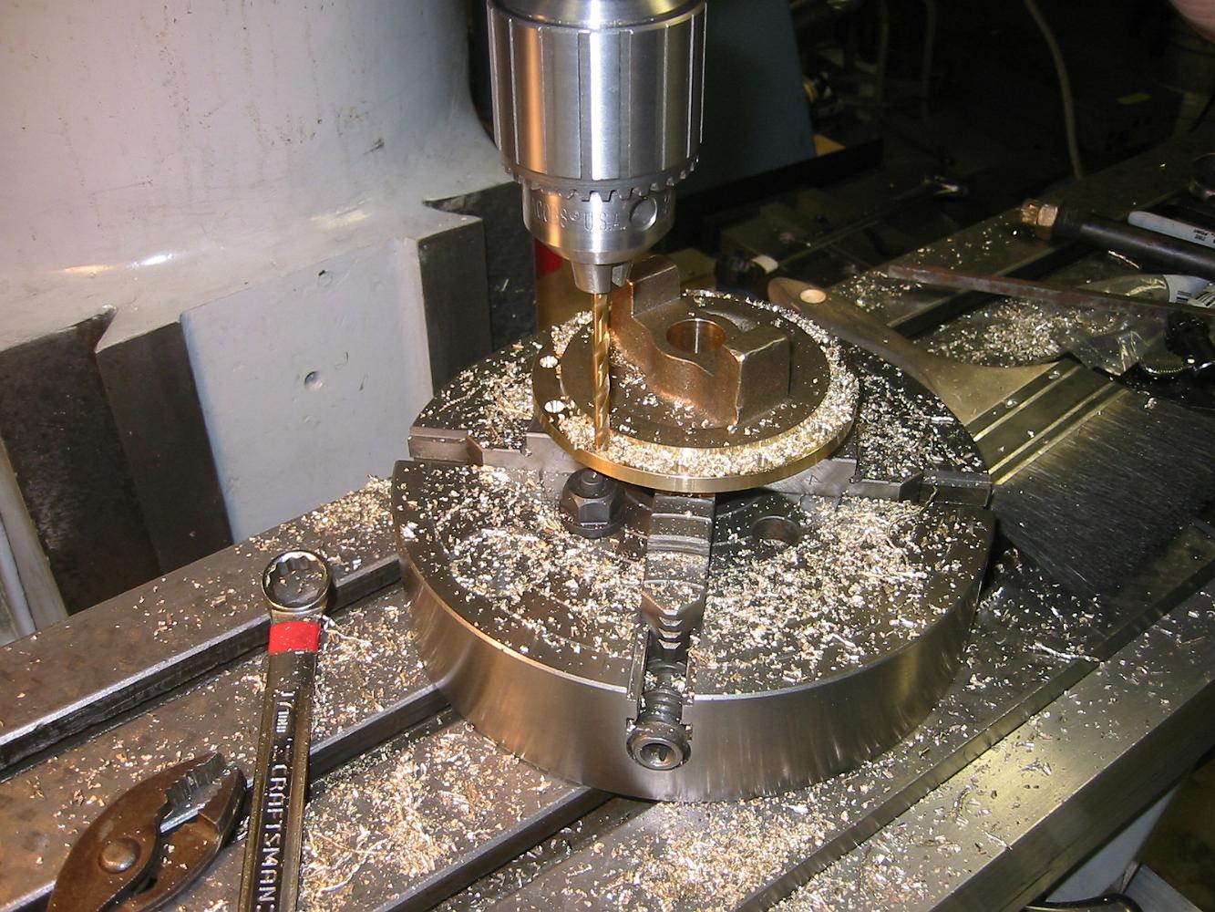
11-Oct-06 Drilling and tapping the piston crosshead guide lugs in a horizontal rotary index friend Alan H. gave me.
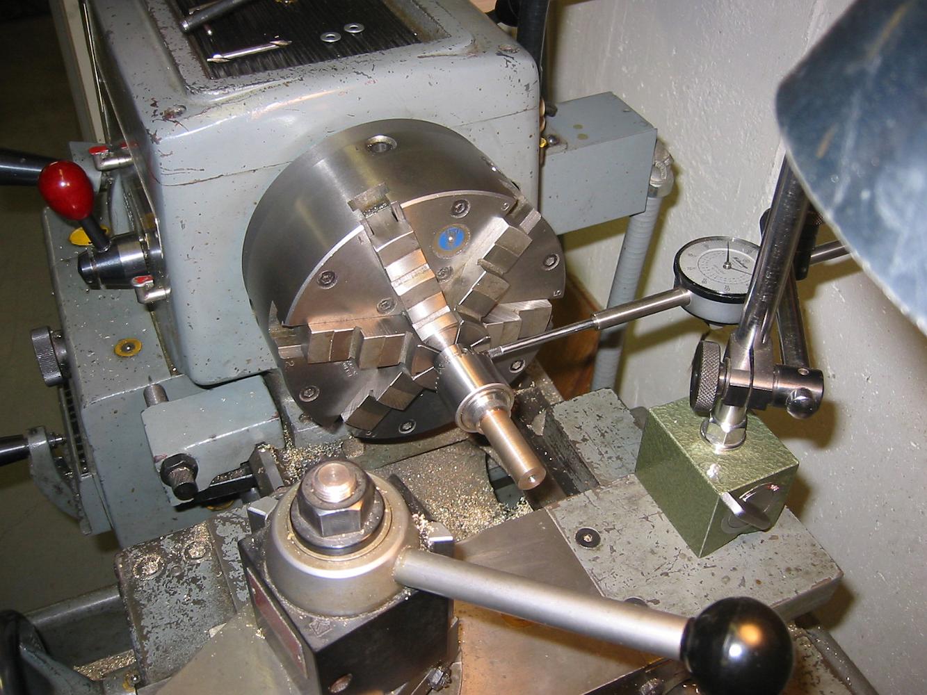
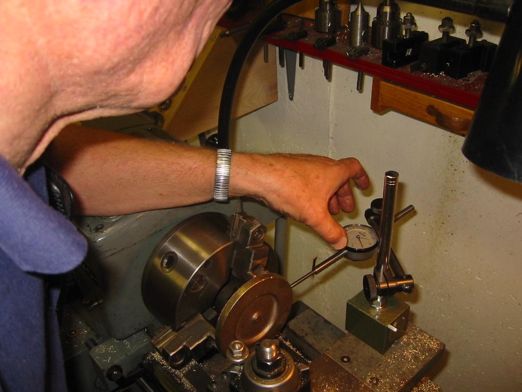
11-Oct-06 Checking the trueness of the horizontal rotary table. Even though it is a used veteran, it runs with 0.0005" runout. Very Nice!
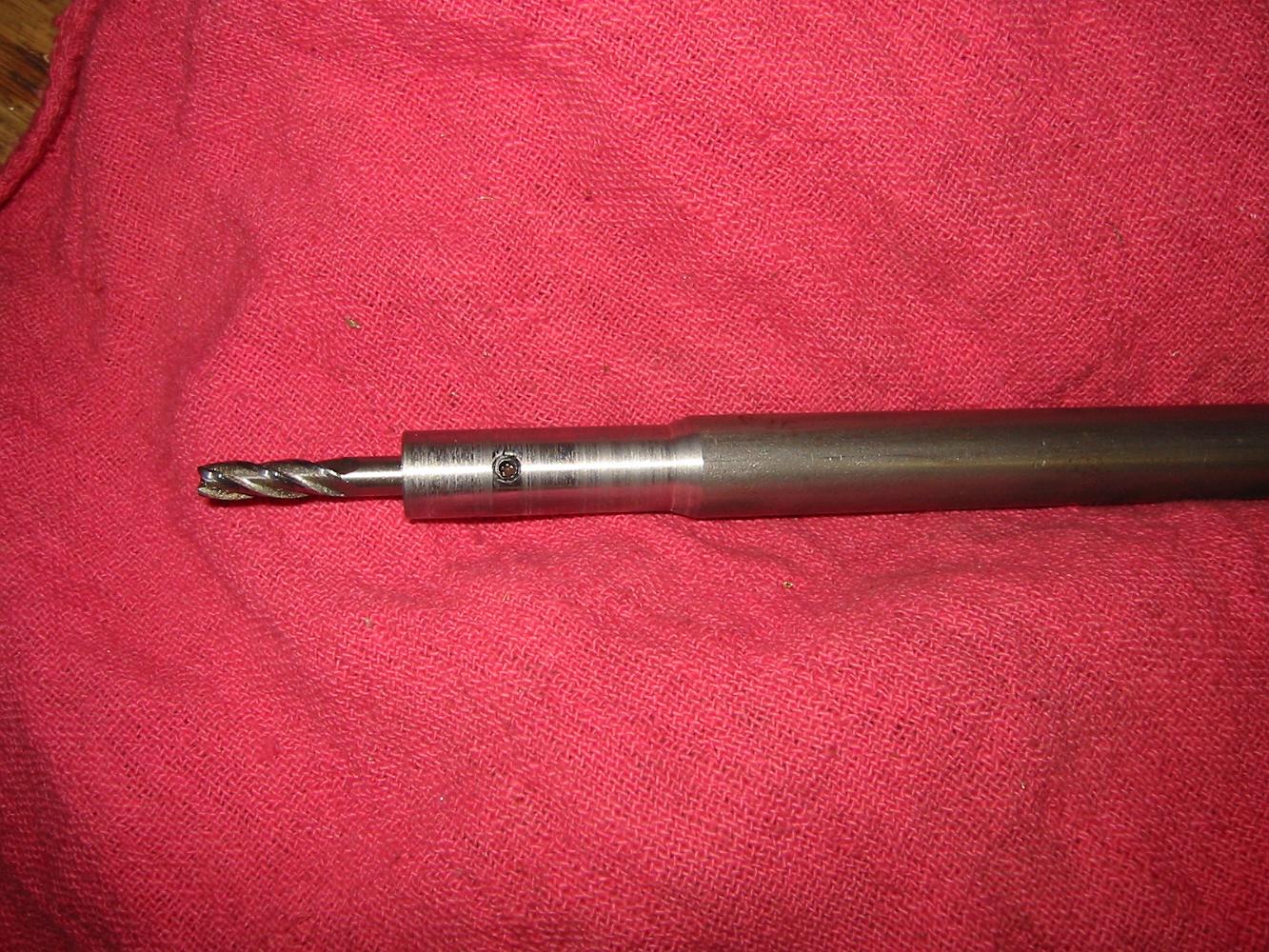
4-Oct-06 We made a custom six inch long end mill holder because the regular end mill holder and spindle would be in the way of where we wanted to mill.
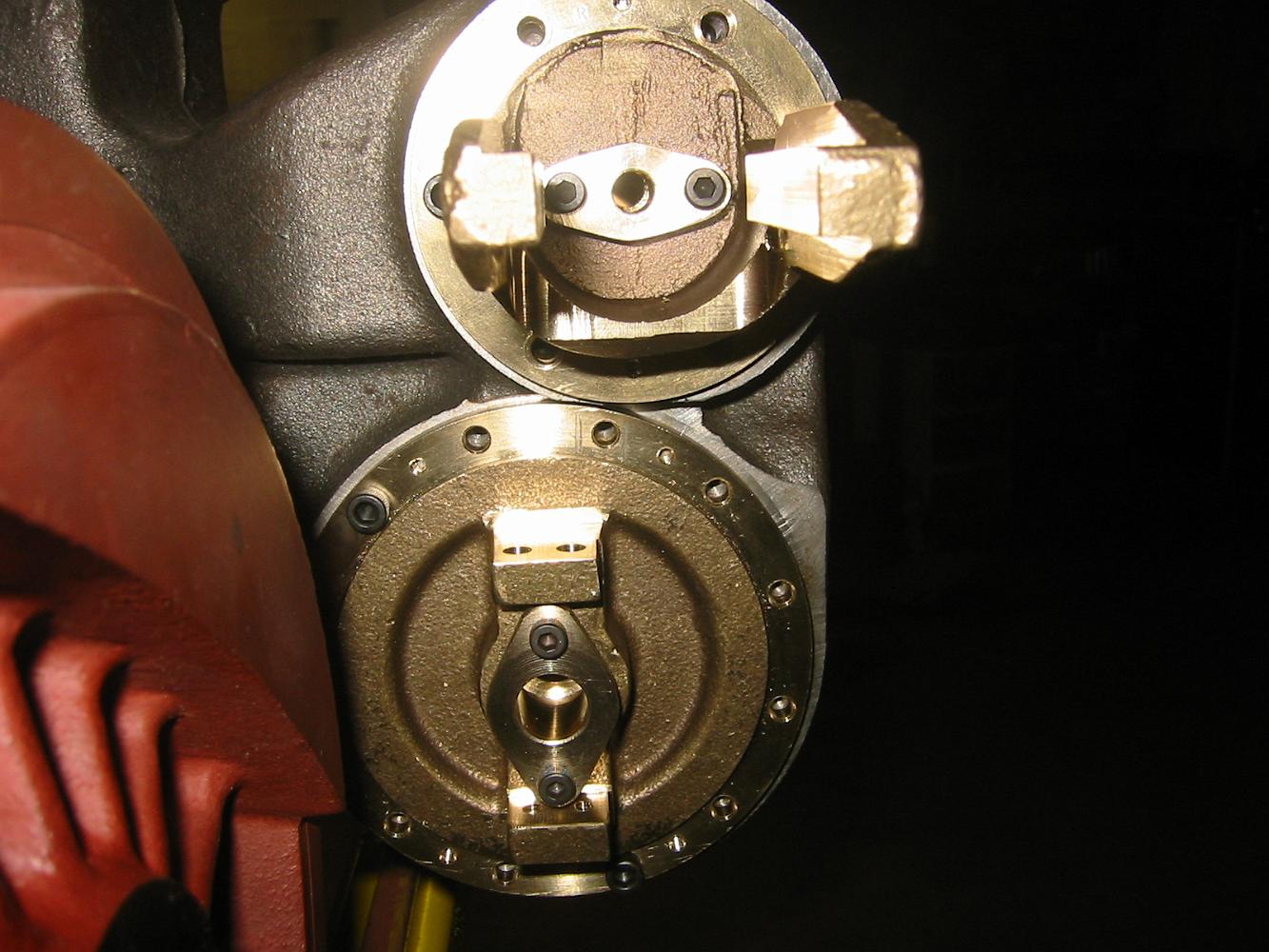
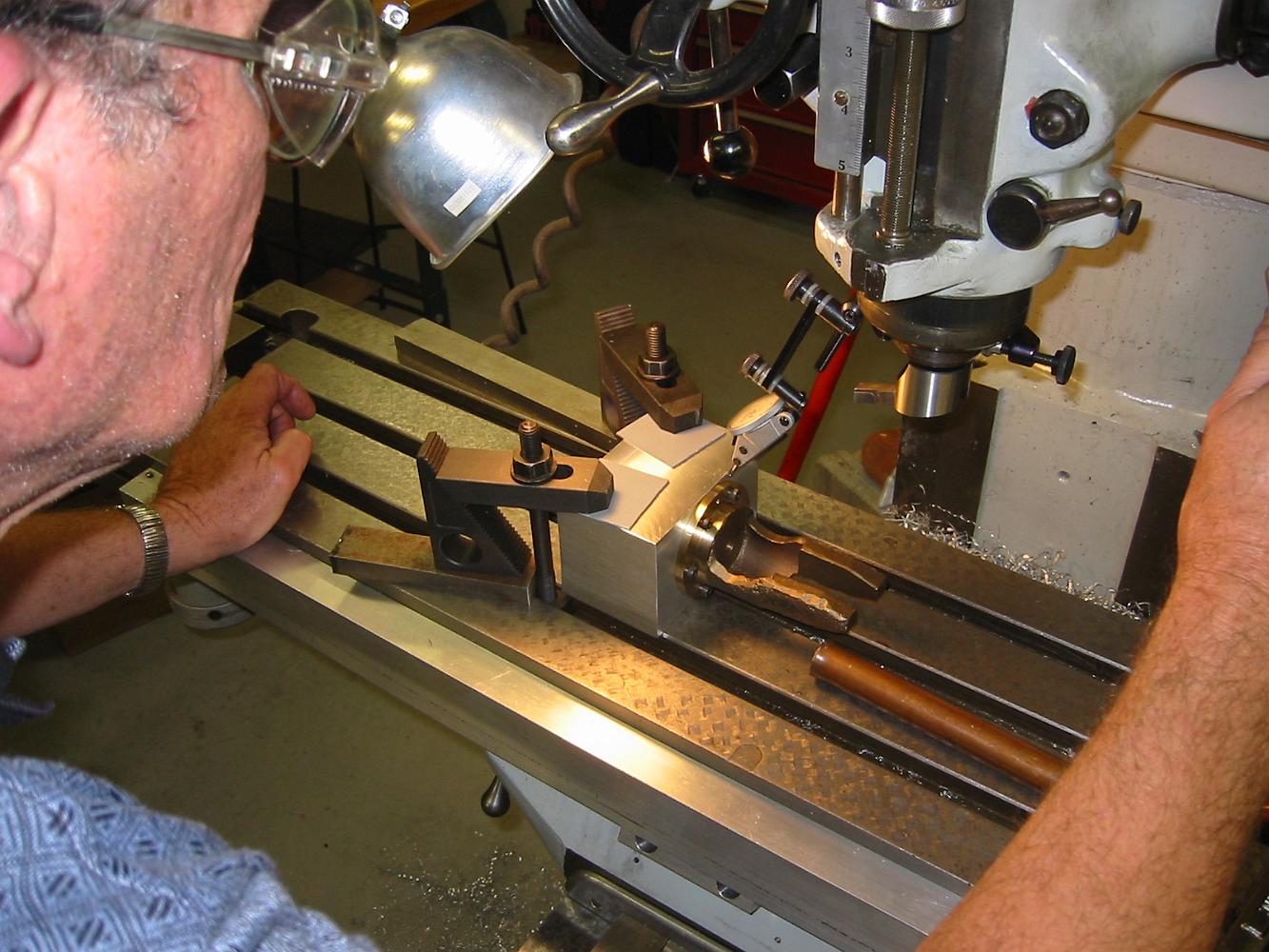
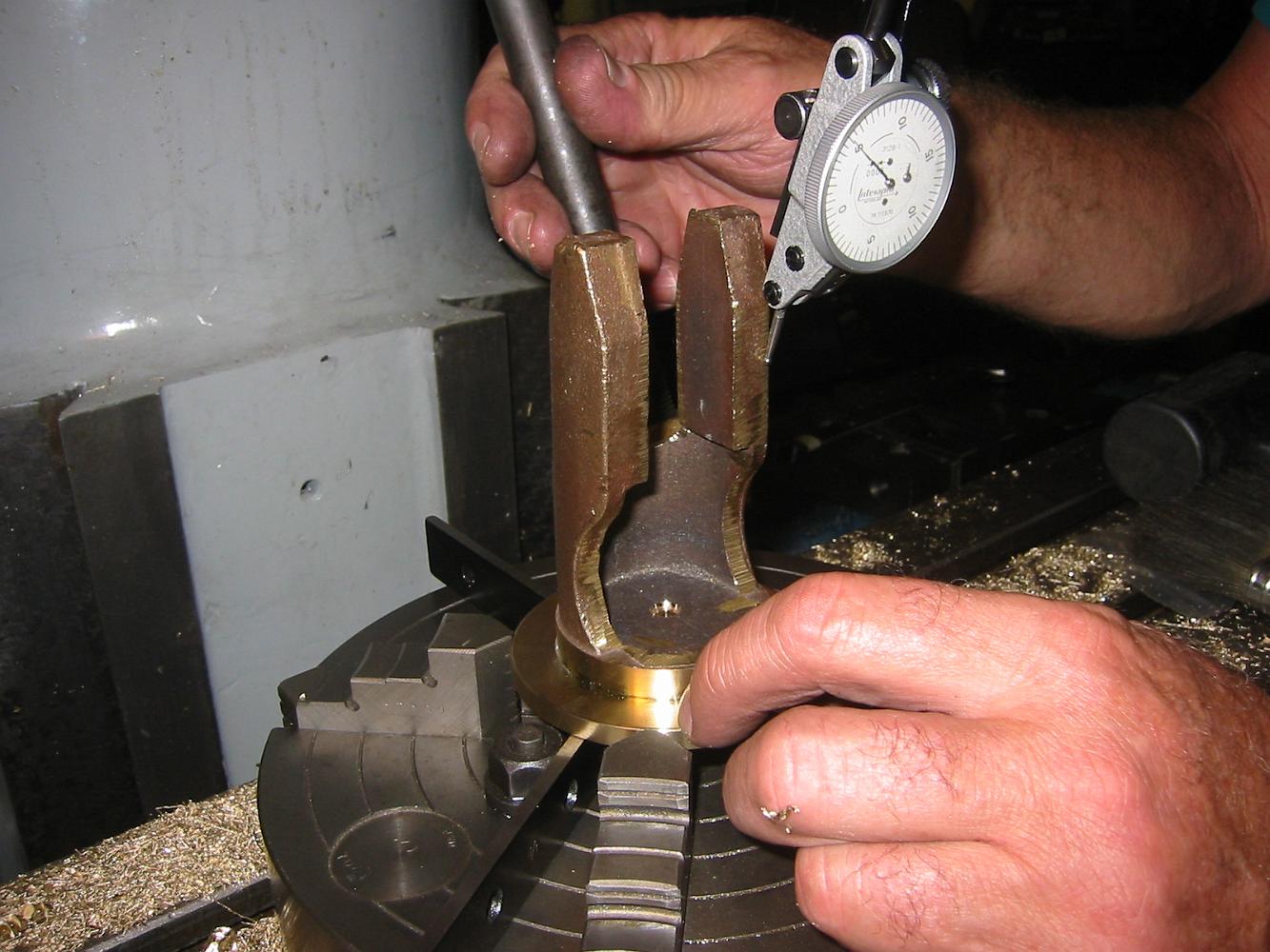
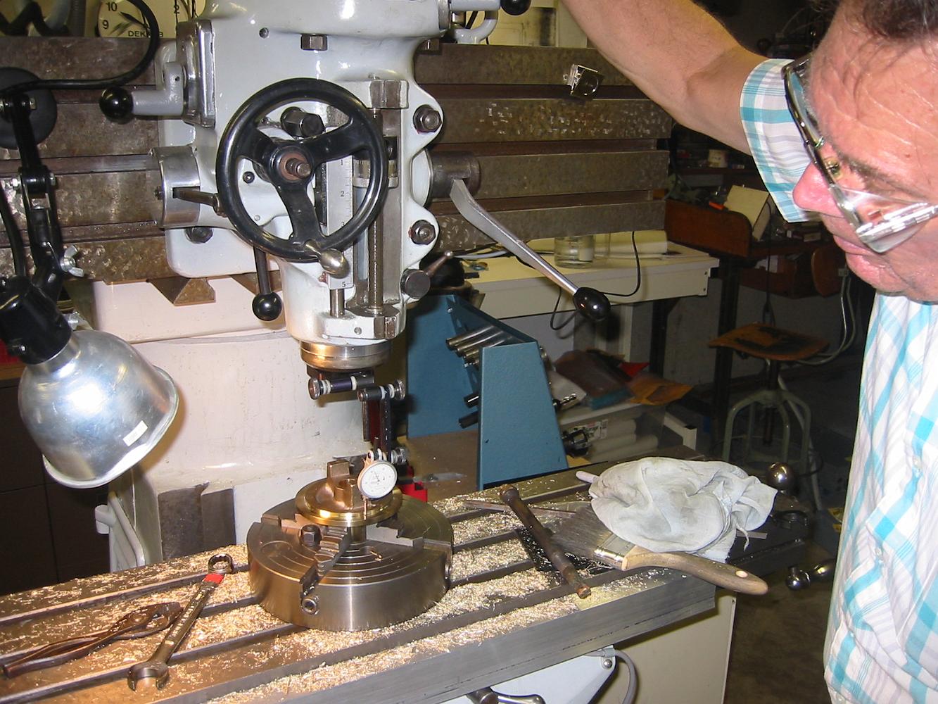
4-Oct-06 Bill taps around on the Rear Valve cover to align the casting in our 'chuck on a table' holder.
4-Oct-06 We discover the holes previously drilled are 0.014 off. We don't know why, maybe the y-axis handle got bumped. We have to make a custom endmill holder…
18-Sept-06 With the finished small Jacobs drill chuck held in the mill, we proceed to drill the rear valve cover holes.
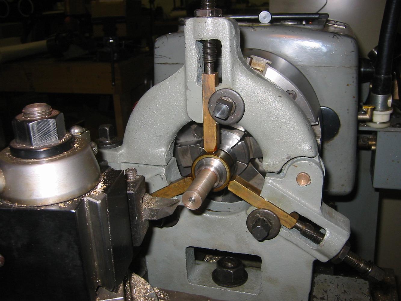
18-Sept-06 Since the center drilled hole in the end of the arbor is way out of center, we use the steady rest to hold the chuck and finish the arbor to size.
18-Sept-06 Making an arbor for a small Jacobs chuck. The drill chuck is clamped to a dowel pin, we indicate off the chuck body to remove the run-out.
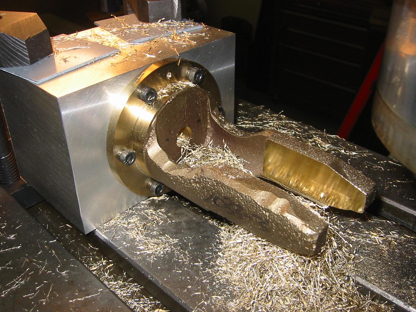
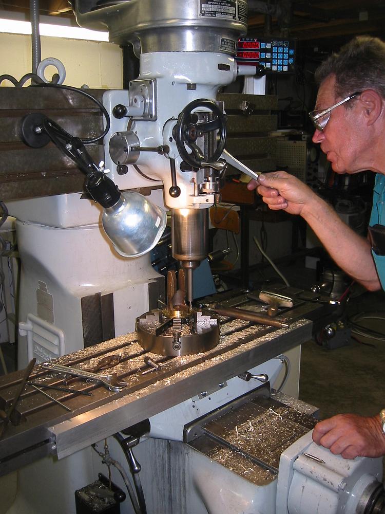
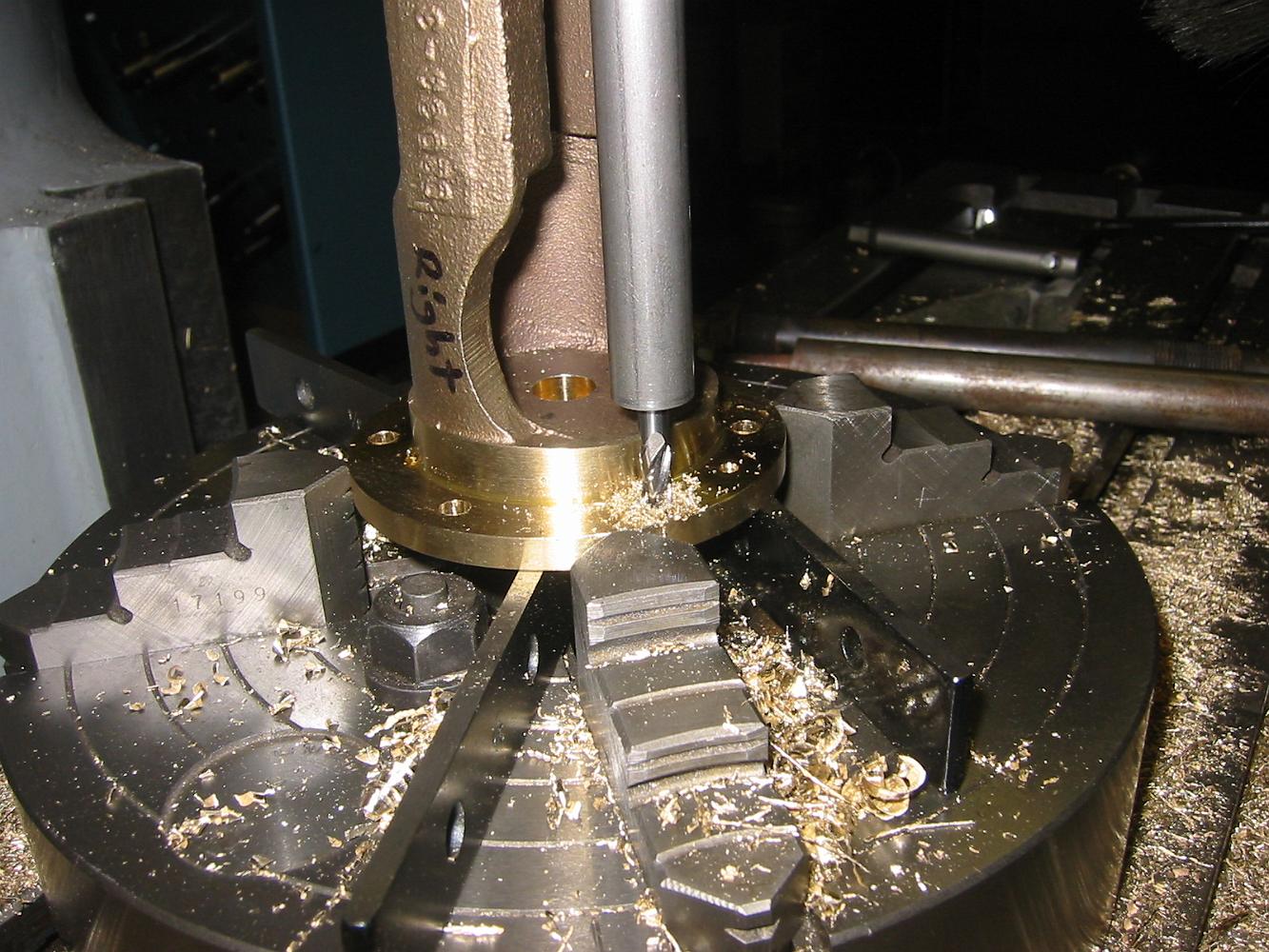
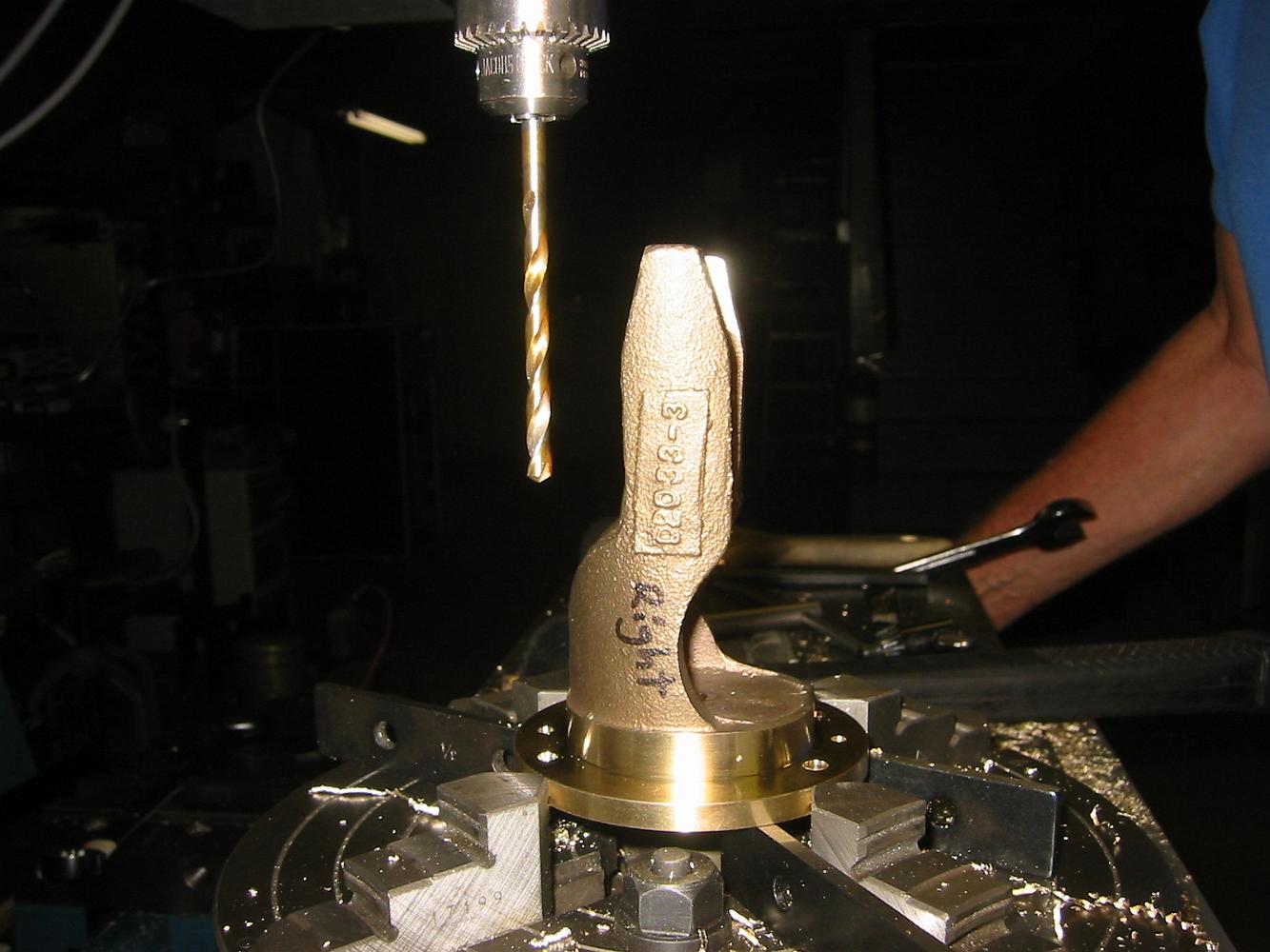
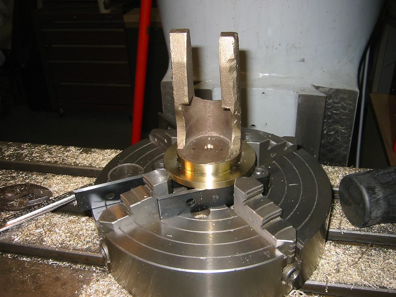
18-Sept-06 The most challenging part to chuck so far - the rear valve/crosshead casting. We will need extra long drills and taps to complete this job.
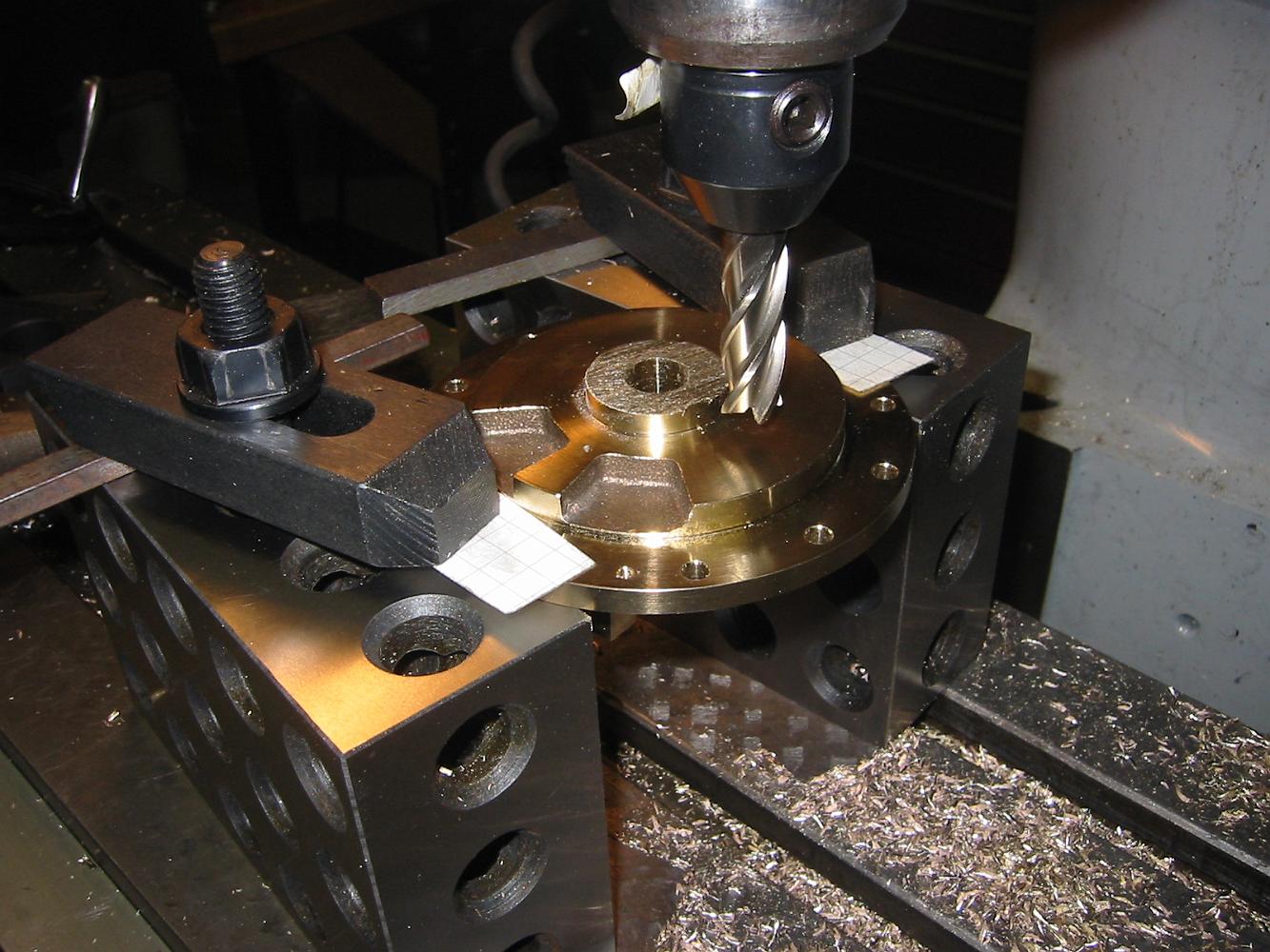
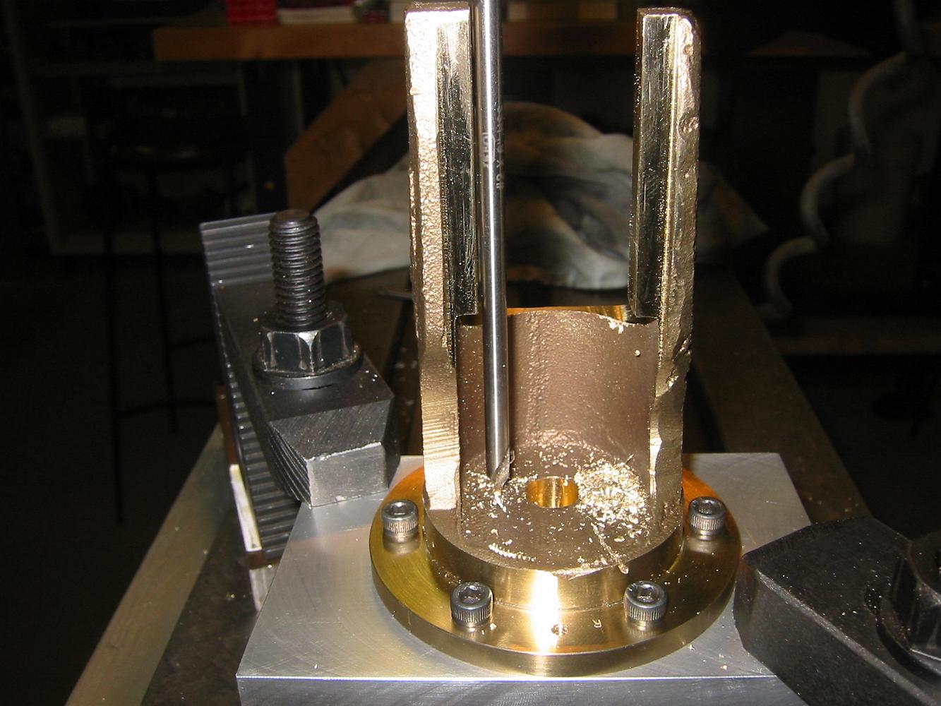
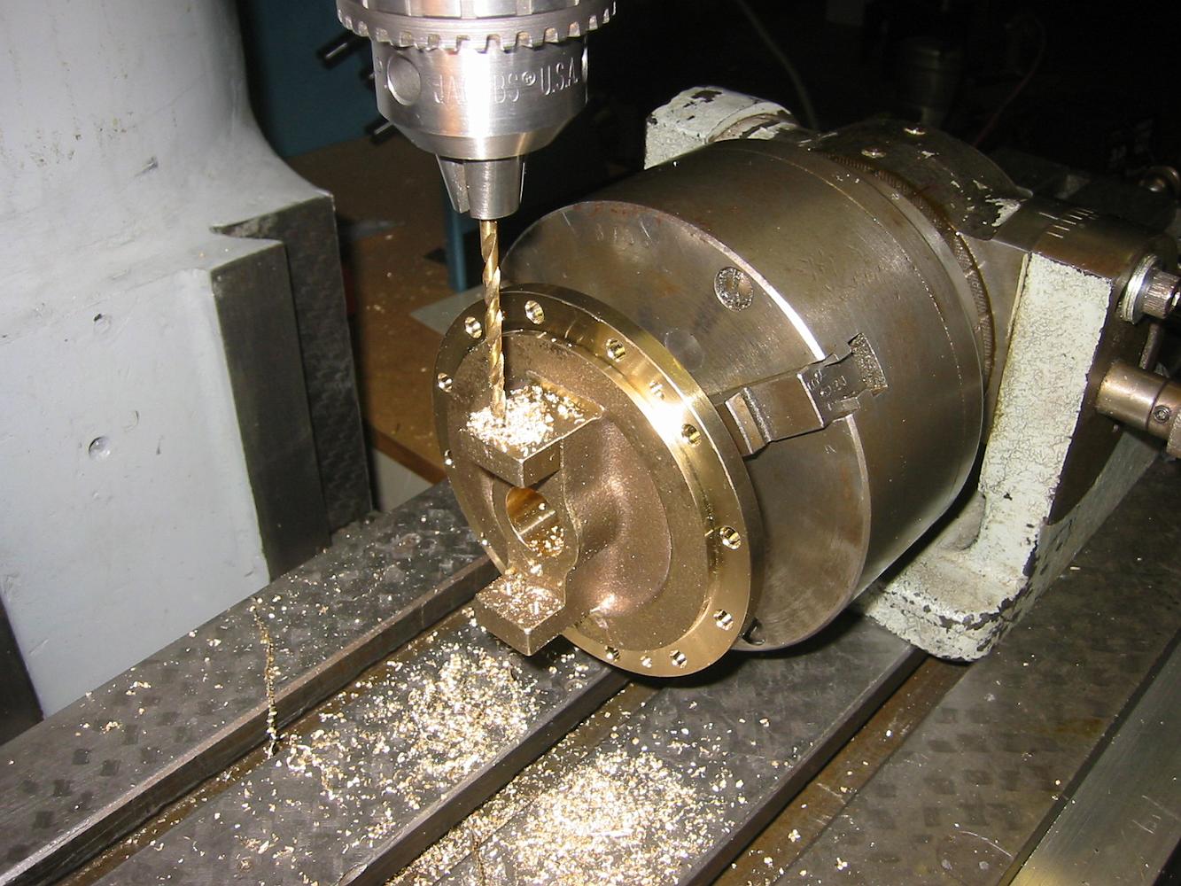
13-Sept-06 Drilling the bolt circle in the rear piston cover. The only way we could hold it was to remove the 4-jaw from the lathe backing plate and bolt the…
2-Aug-06 A thin grab in the 3-jaw. With the parallels temporarily in place to try and make the outside parallel with the inside, the piston cover is chucked up…
26-July-06 How to set a carriage stop when you do not have a micrometer stop. Use something, in case a drill bit, which is the same size of the offset you are…