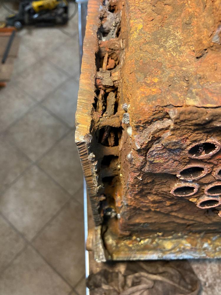
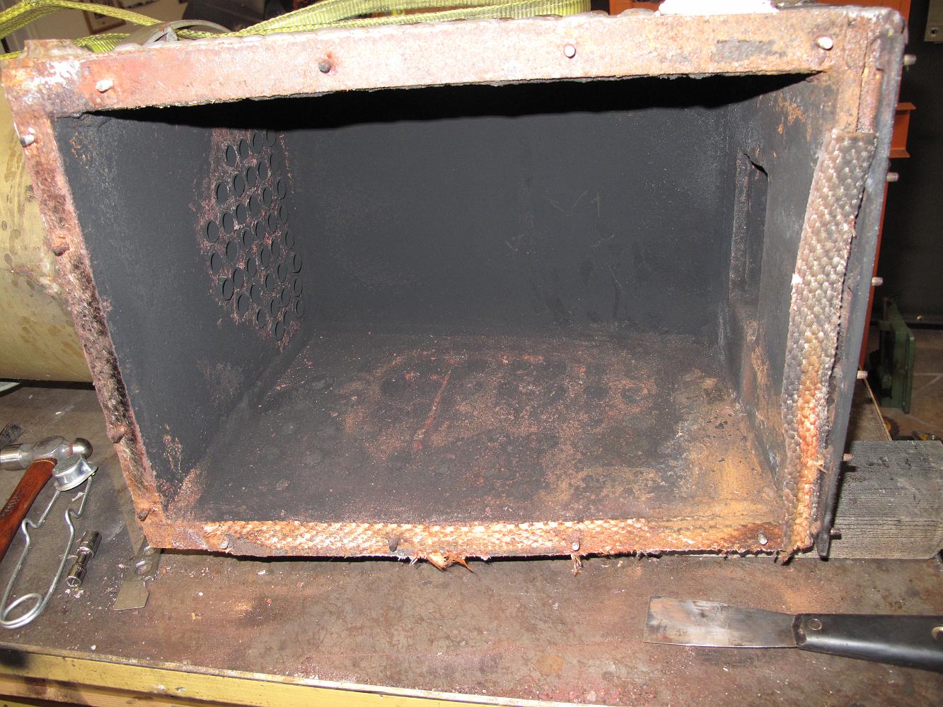
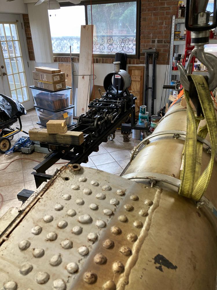
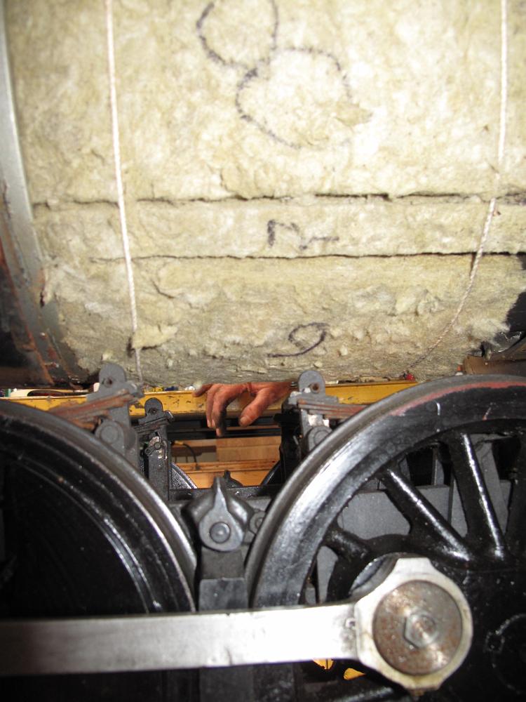
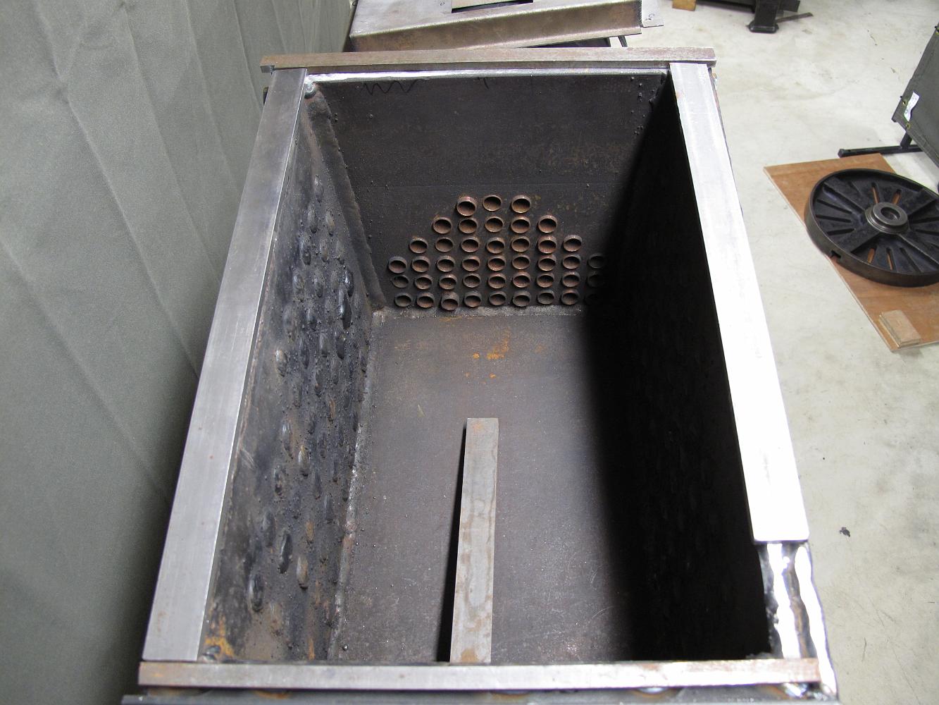
23-Jan-2022 With the firebox off the boiler, we can clearly see how packed up the tiny 5/8" water space is between the outside shell and the firebox. The 3/8"…
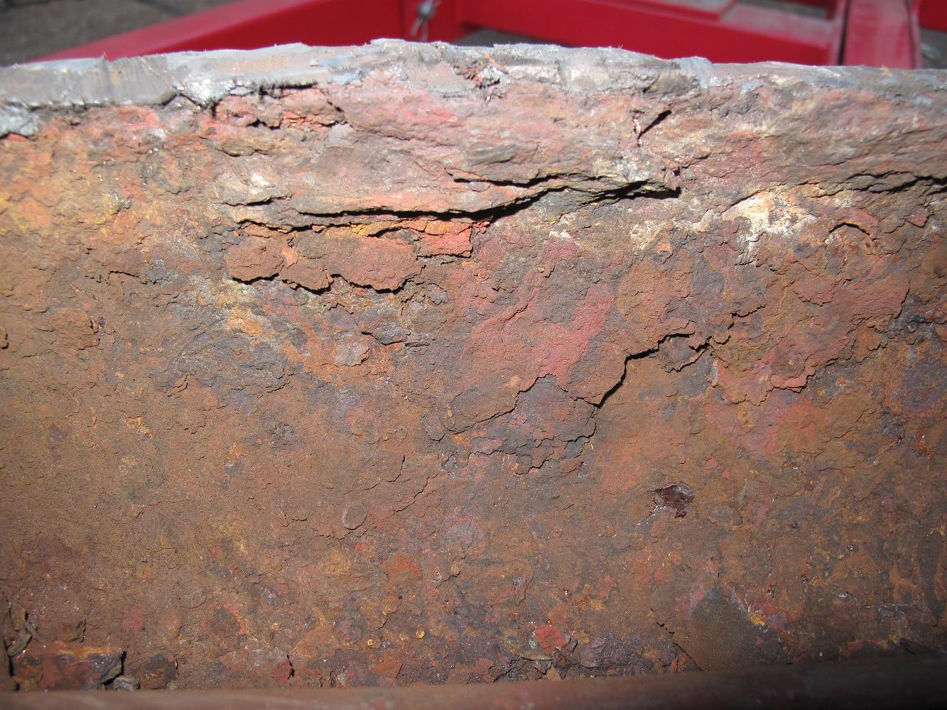
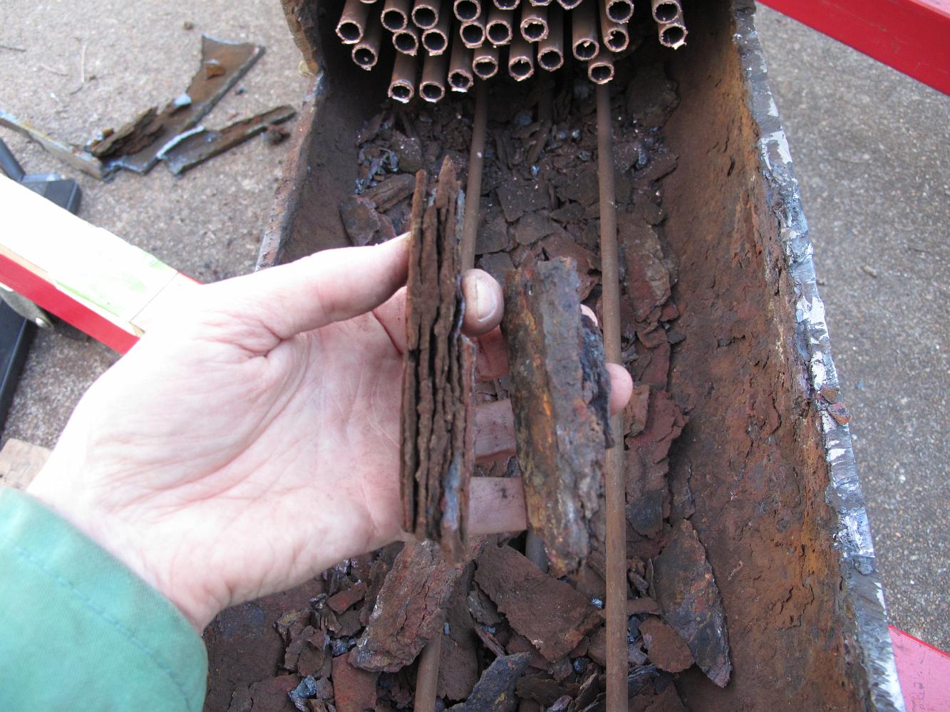
22-Jan-2022 The crown sheet and crown bars _after_ cleaning. The steel was delaminating, layer by layer.
22-Jan-2022 All the debris from the crownsheet fell into the upside down boiler shell from sawing and beating we were doing to separate the firebox. Some of…
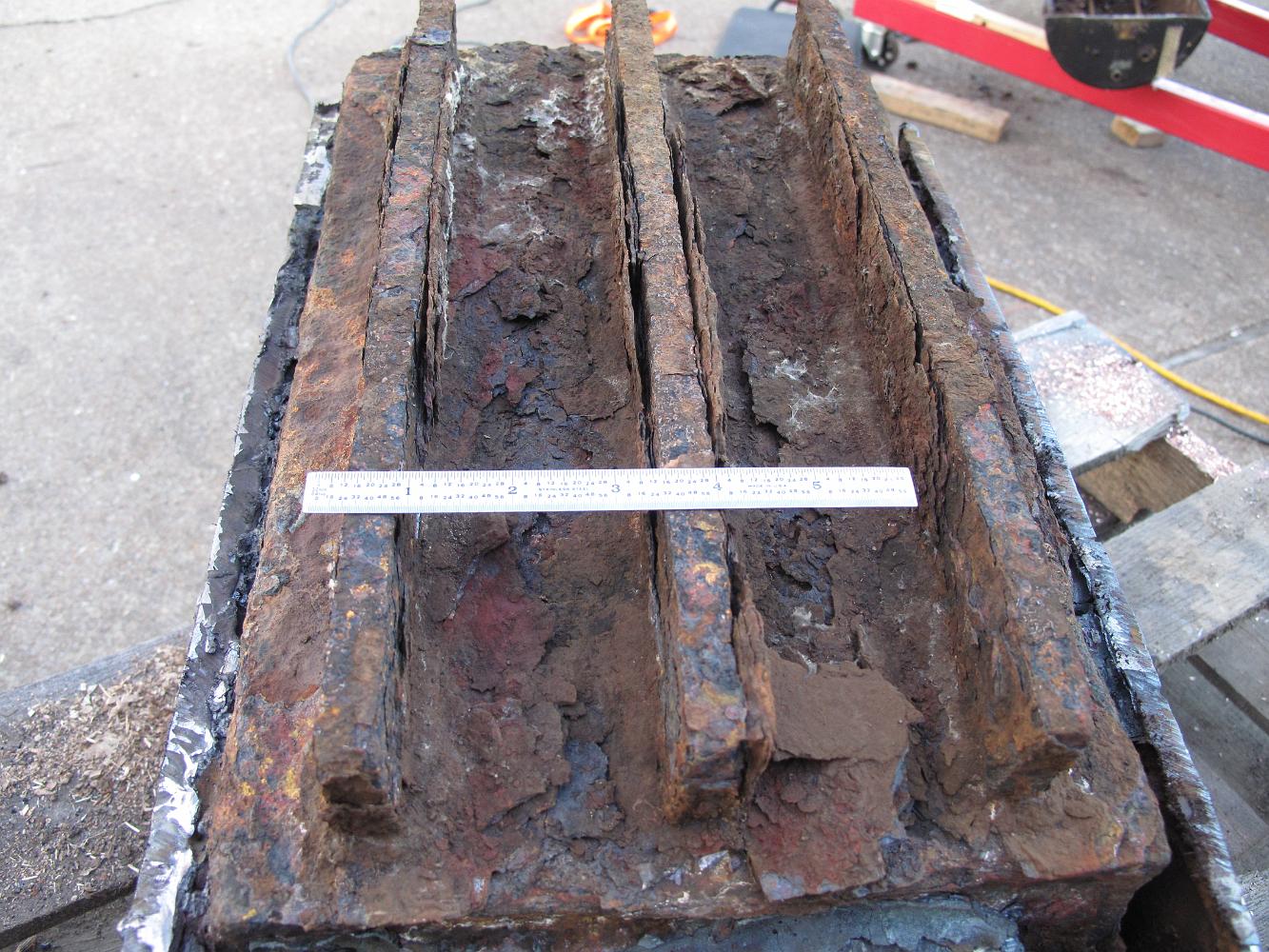
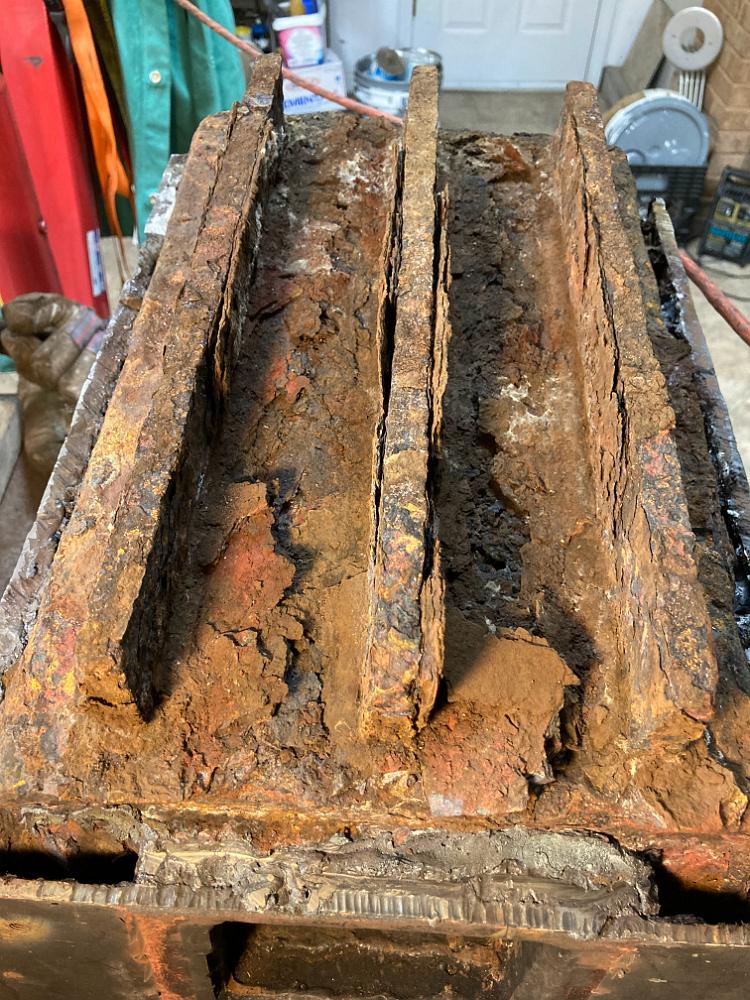
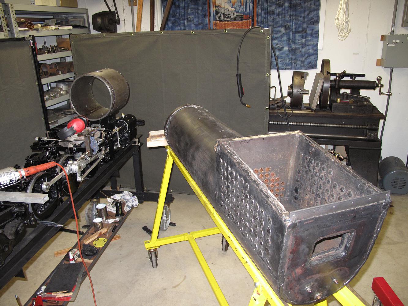
22-Jan-2022 The firebox is freed from the boiler tube and the flues. I can finally see how badly eroded the crown bars are. They were 1/2"x2"x16" new.
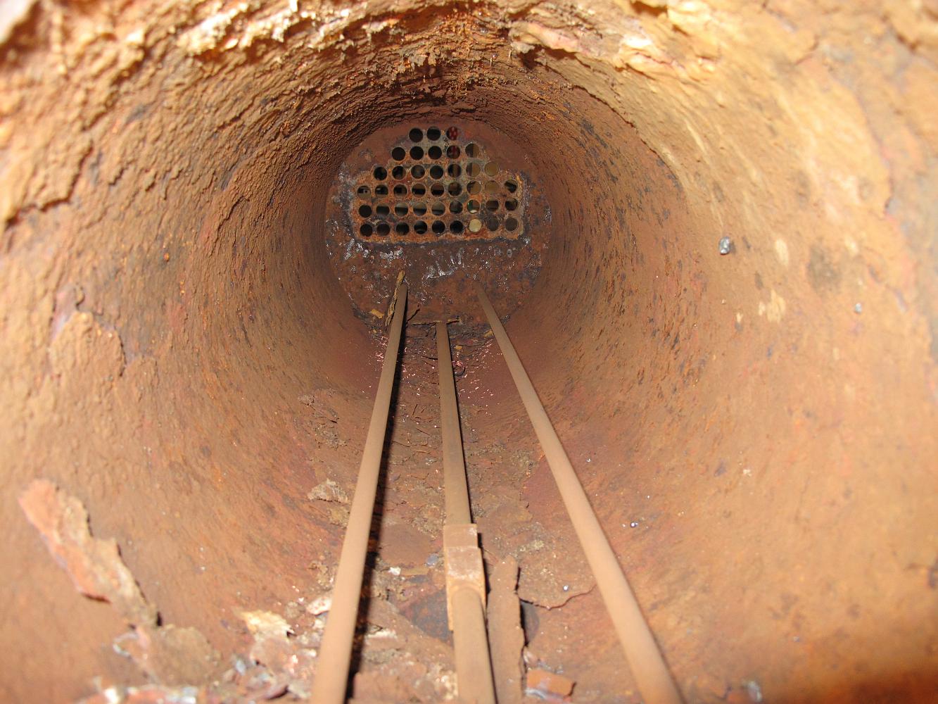
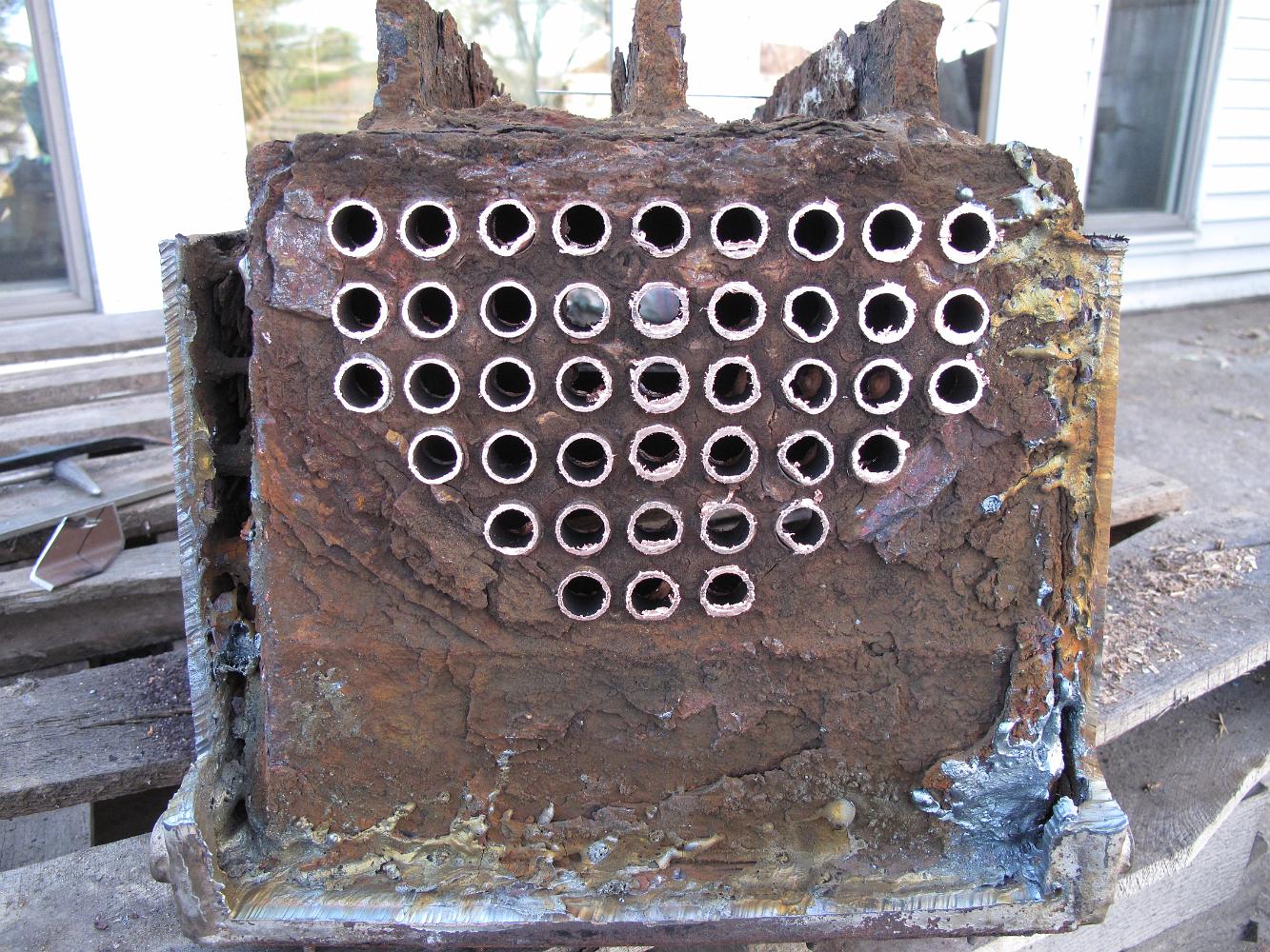
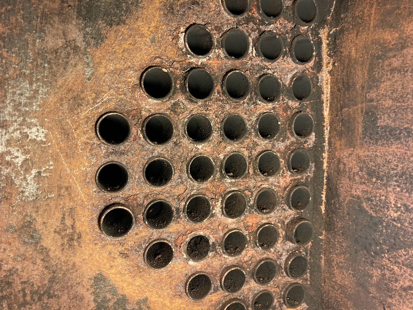
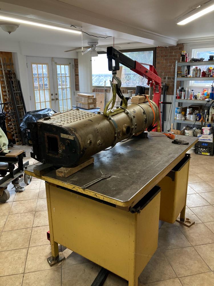
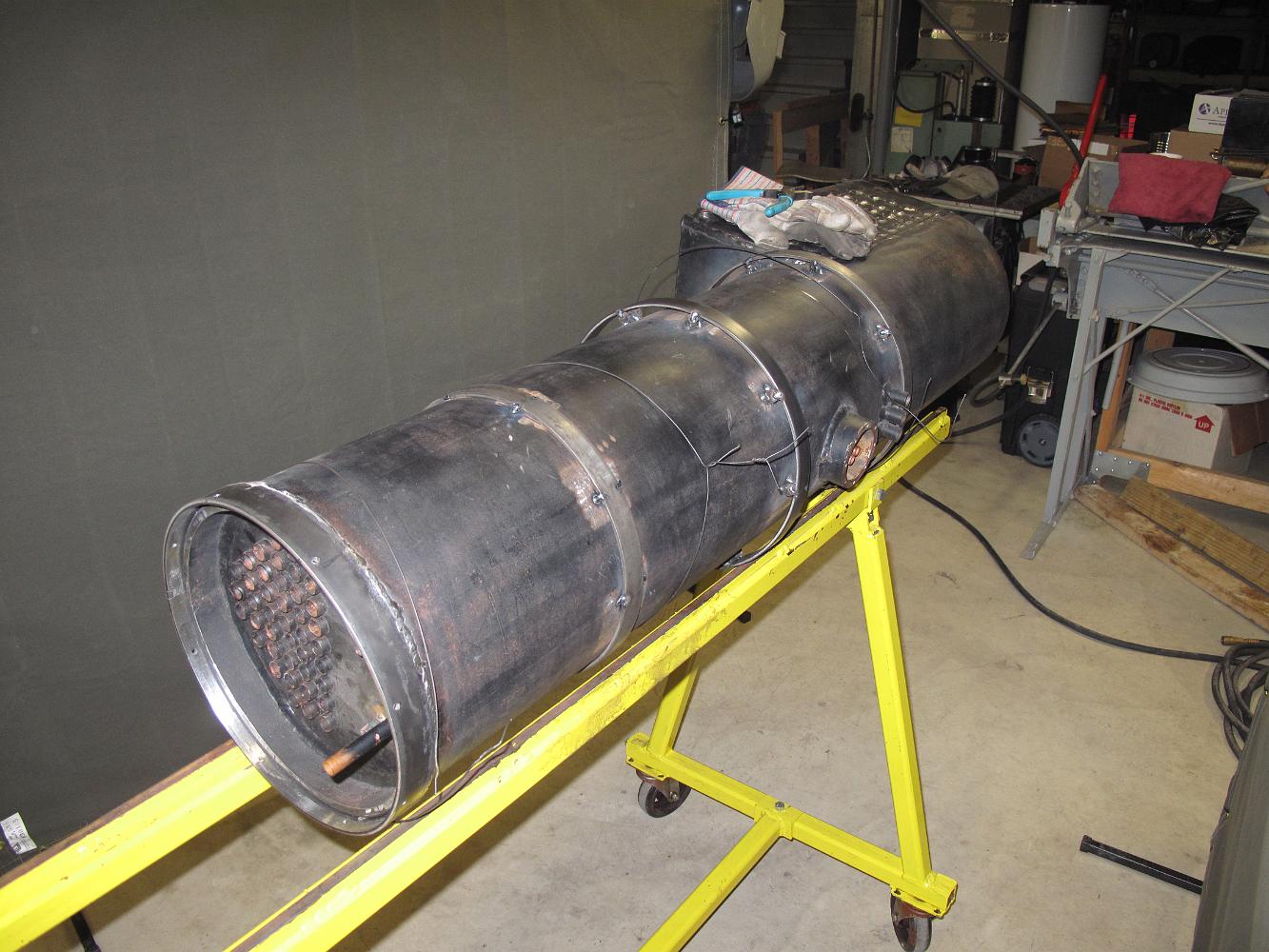
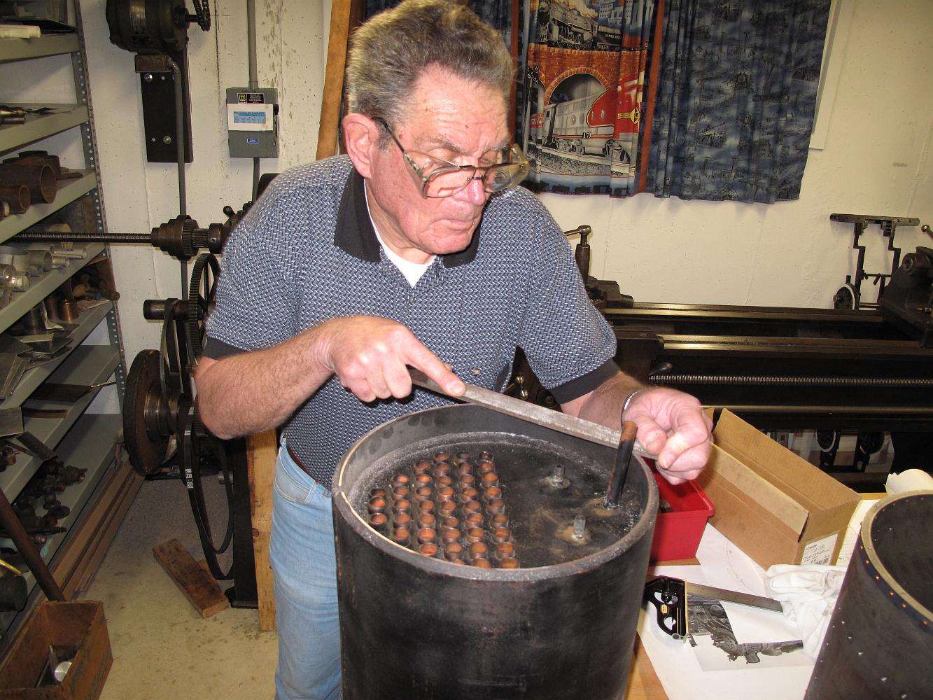
22-Jan-2022 I'm impressed how well the 42 1/2" copper flues are anchored into the front fluesheet. I've drilled and reamed them in an effort to loosen them,…
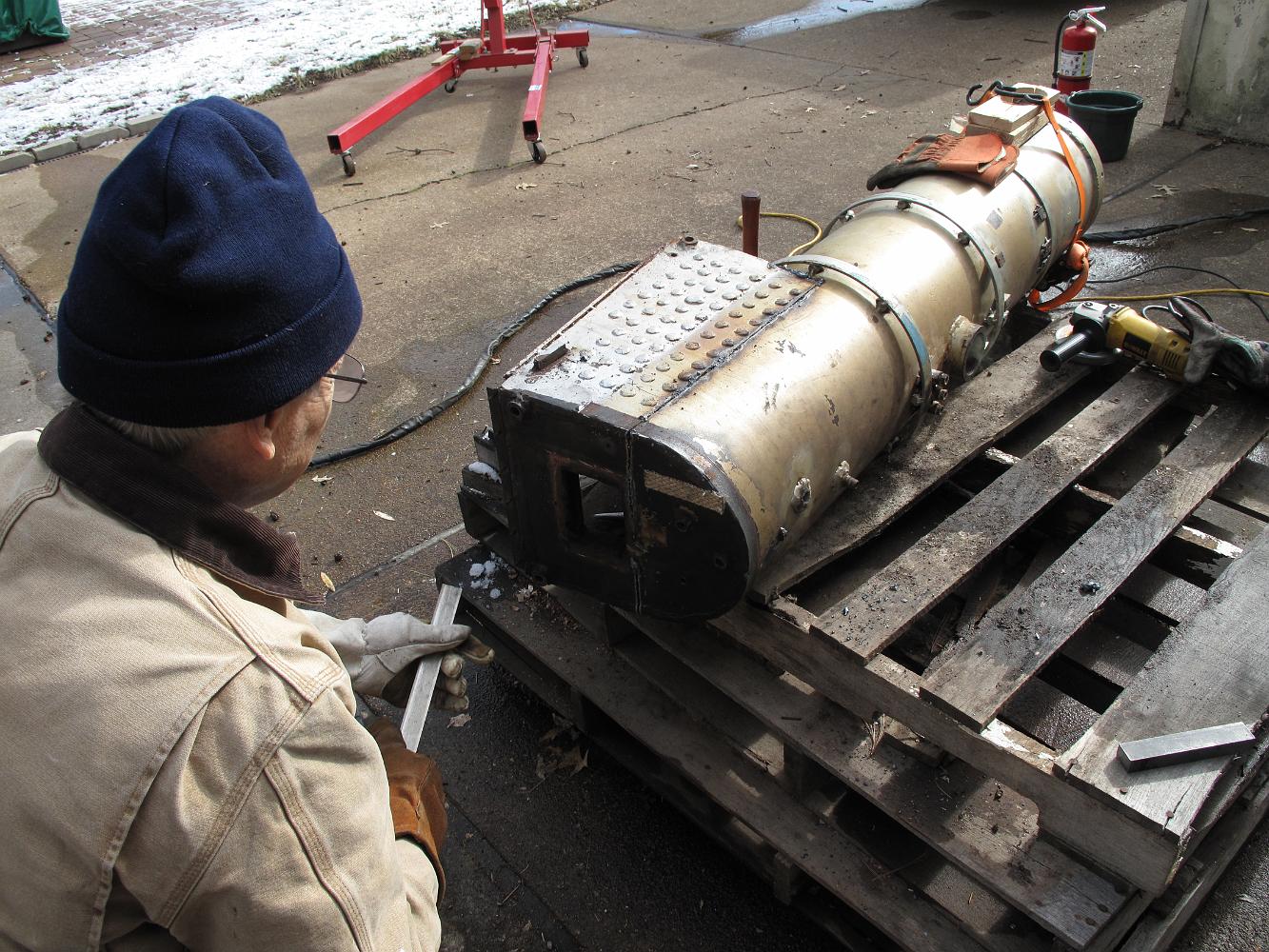
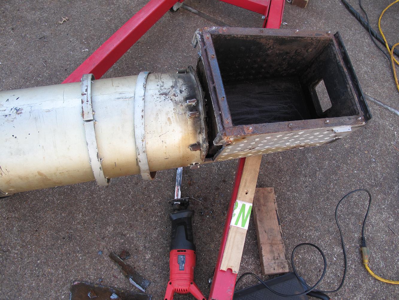
17-Jan-2022 Rich's plasma cutter makes neat and quick work separating the firebox from the boiler tube. I spend the next couple of days trying to drill and…
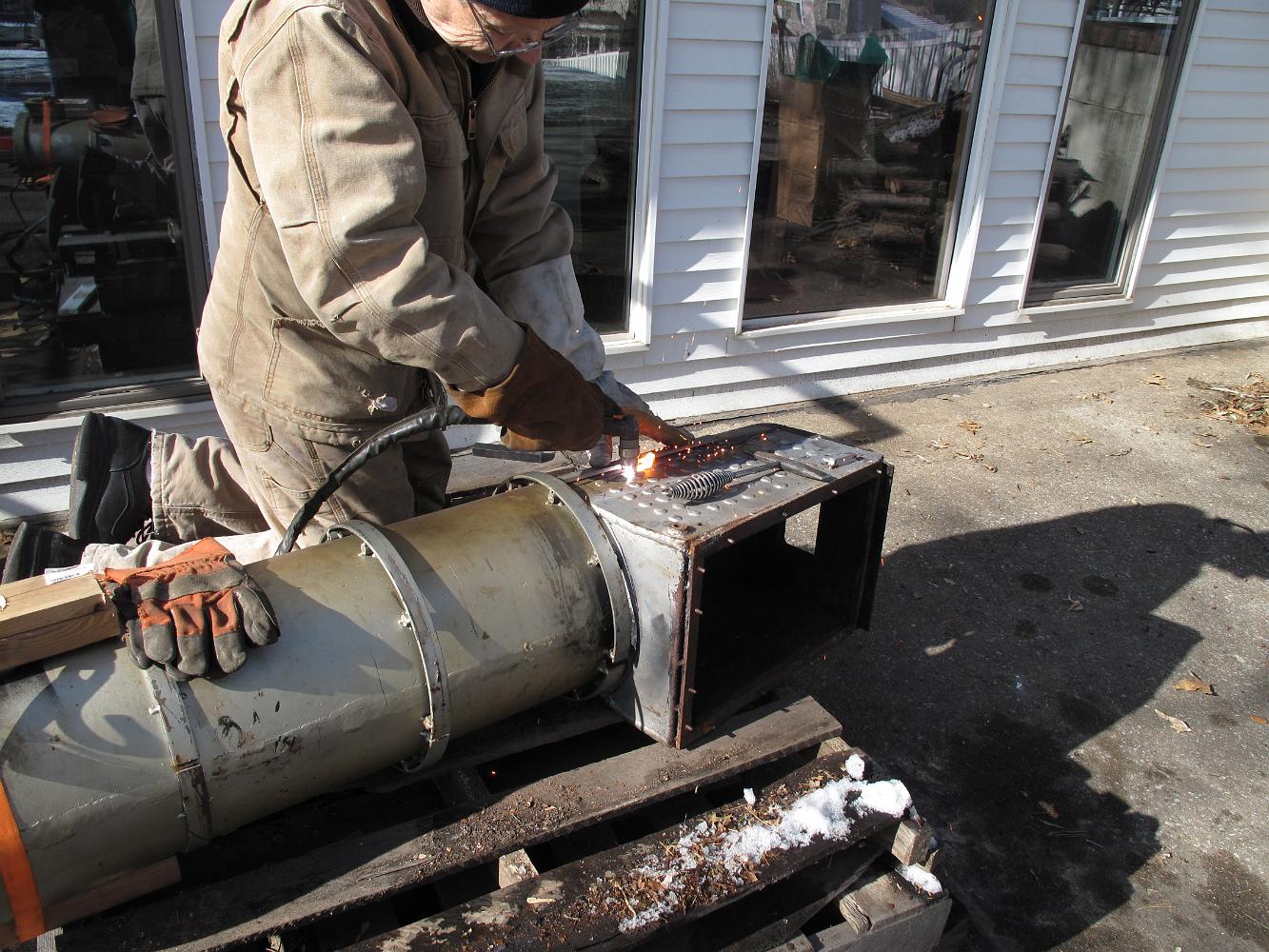
17-Jan-2022 Richard Rahn uses his plasma torch to cut the firebox away from the boiler tube. I hope I can re-use the tube and just replace the firebox.
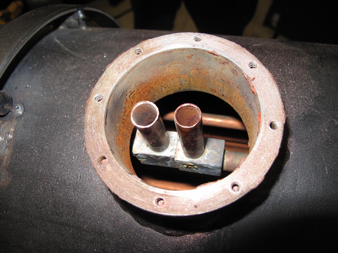
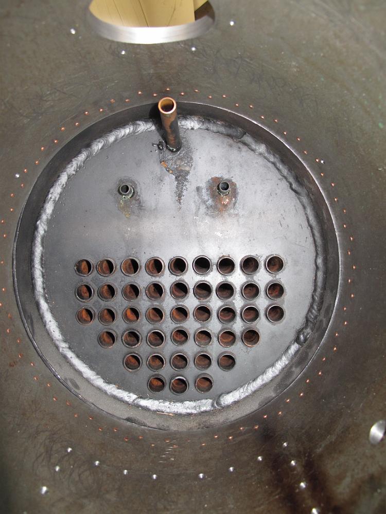
27-Dec-2021 A close inspection in the firebox shows a small amount of corrosion of the steel around the flues, but the flues themselves are in good shape, the…
27-Dec-2021 View of the firebox and the failure. The engineers side sheet failed with a hole about the size of pencil lead in the back right side. The stripe of…
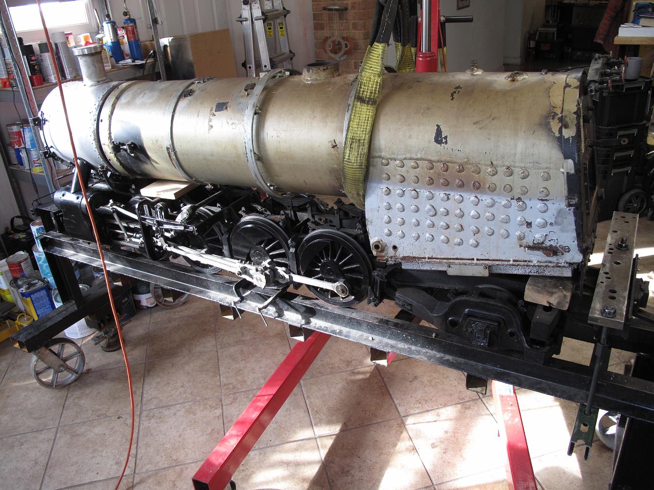
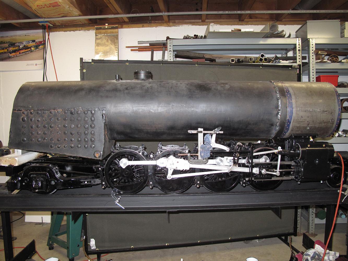
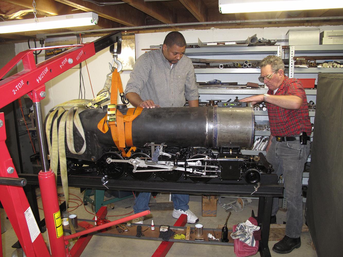
27-Dec-2021 The boiler and Chassis are separated for the first time in 15 years.
27-Dec-2021 Using the shop crane, the boiler is removed from the chassis.
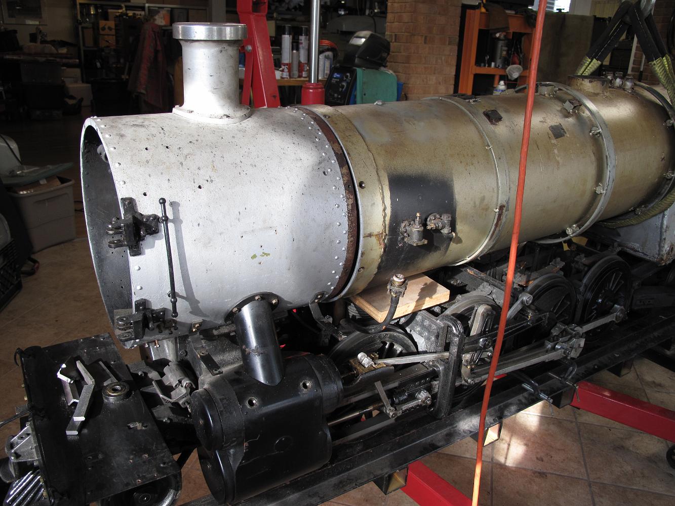
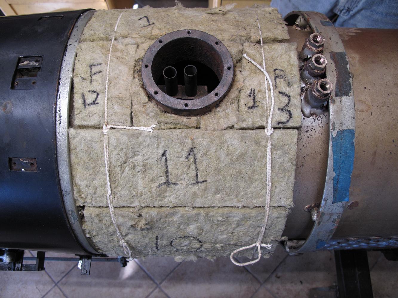
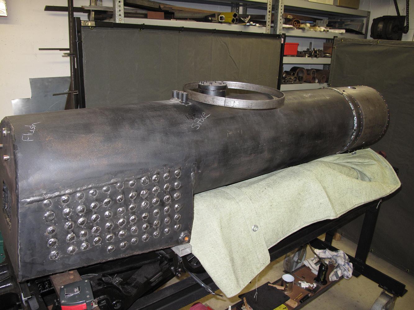
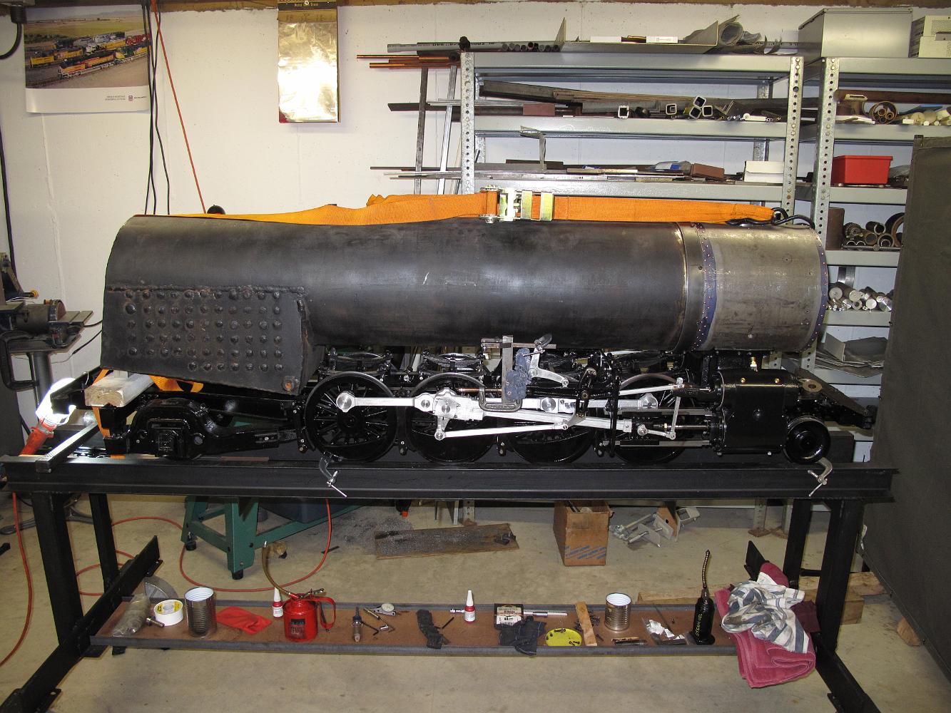
27-Dec-2021 She looks a bit gangly without any jacketing. I am very happy to find the exterior condition of the boiler shell is excellent, with very little…
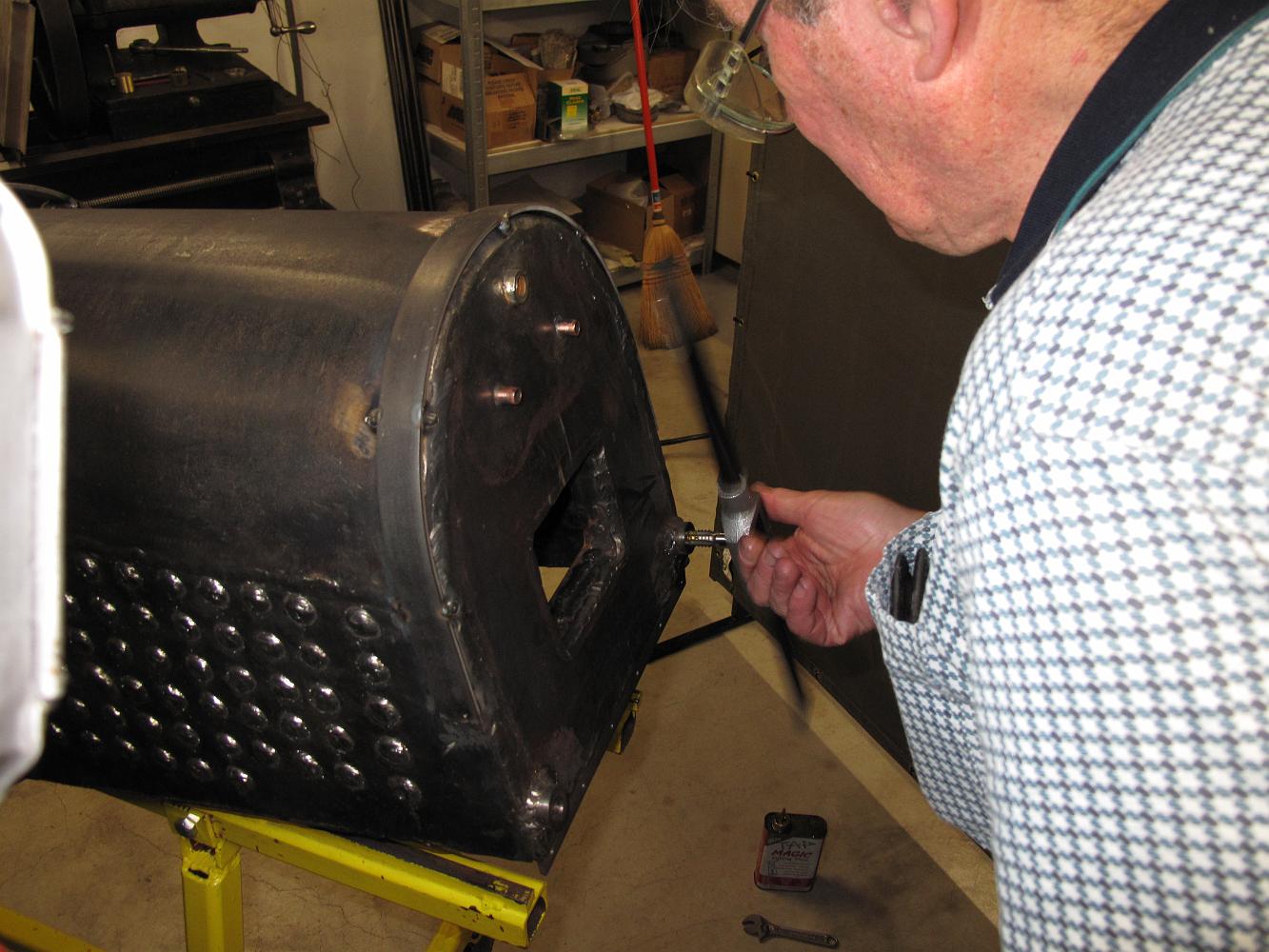
27-Dec-2021 The boiler has been stripped of all plumbing, accessories, cab shell and jacketing in preparation for removal from the chassis.
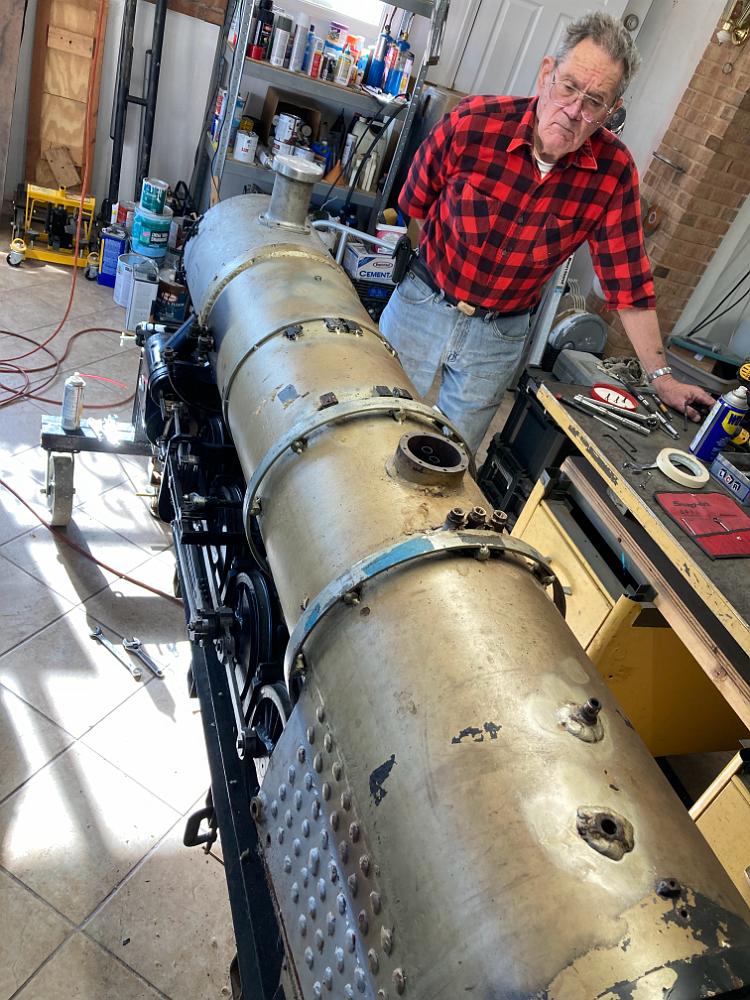
20-Dec-2022 Bill and I prepare to remove the boiler from the chassis, but leave the smokebox bolted to the cylinder saddle.
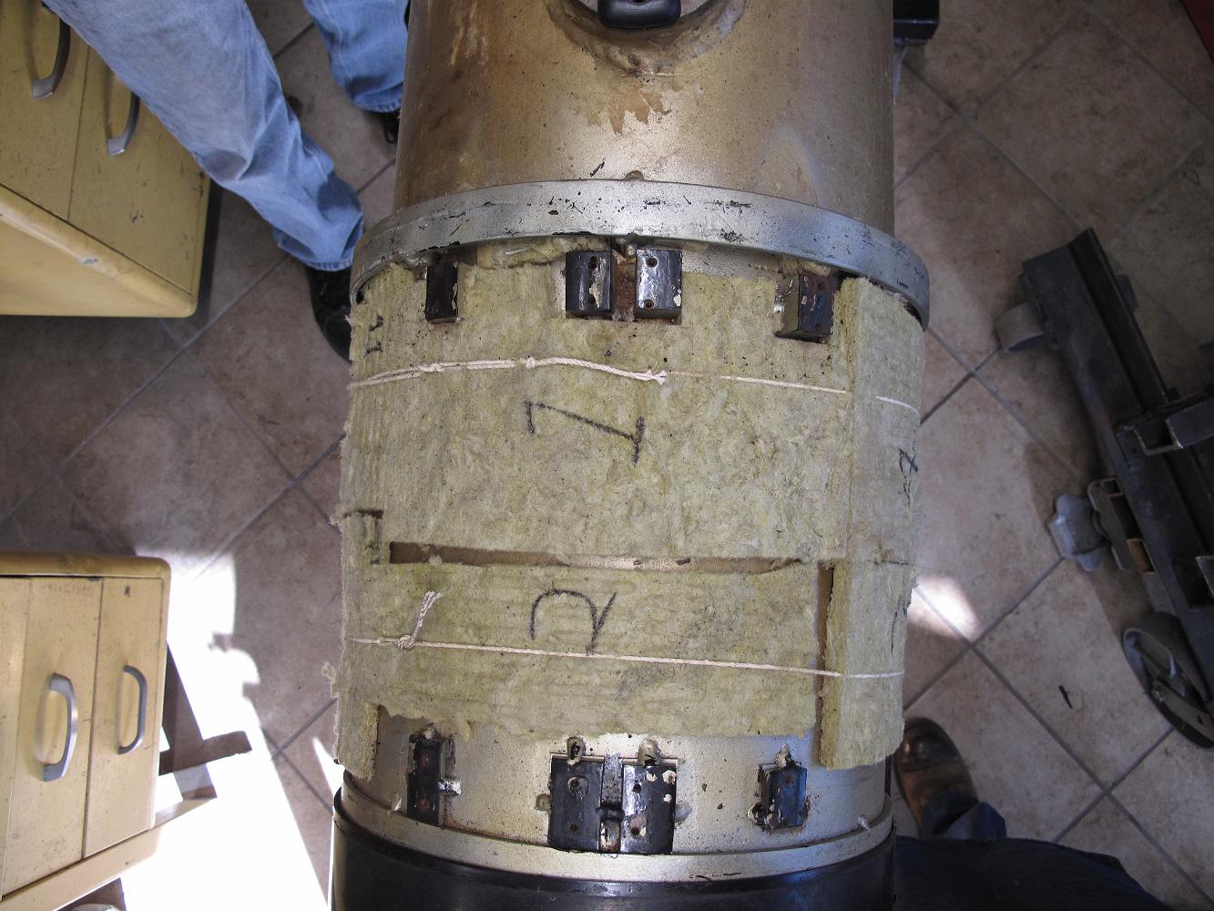
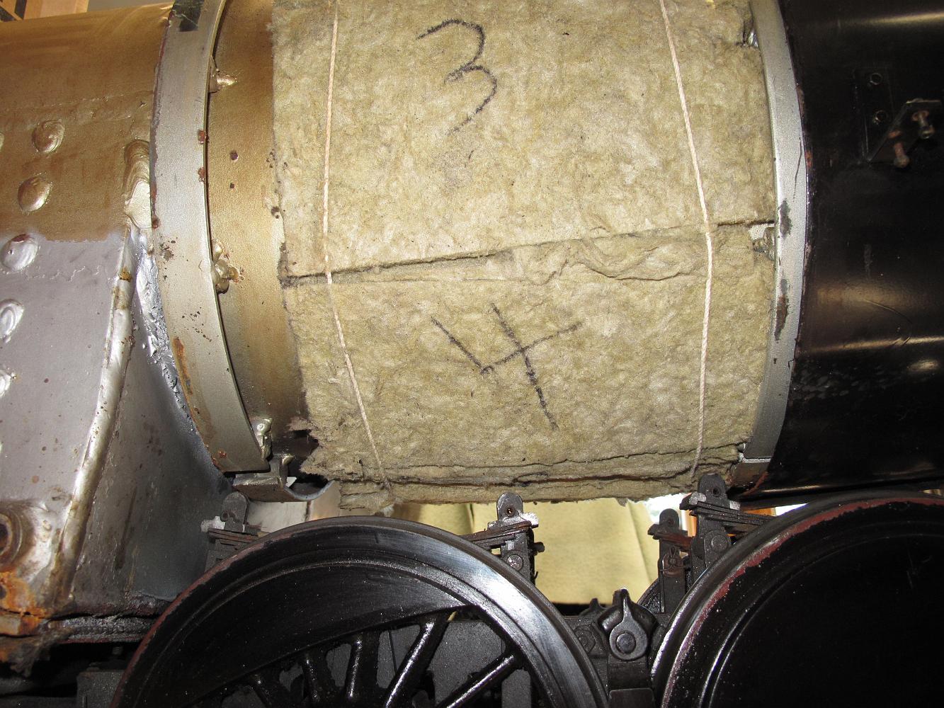
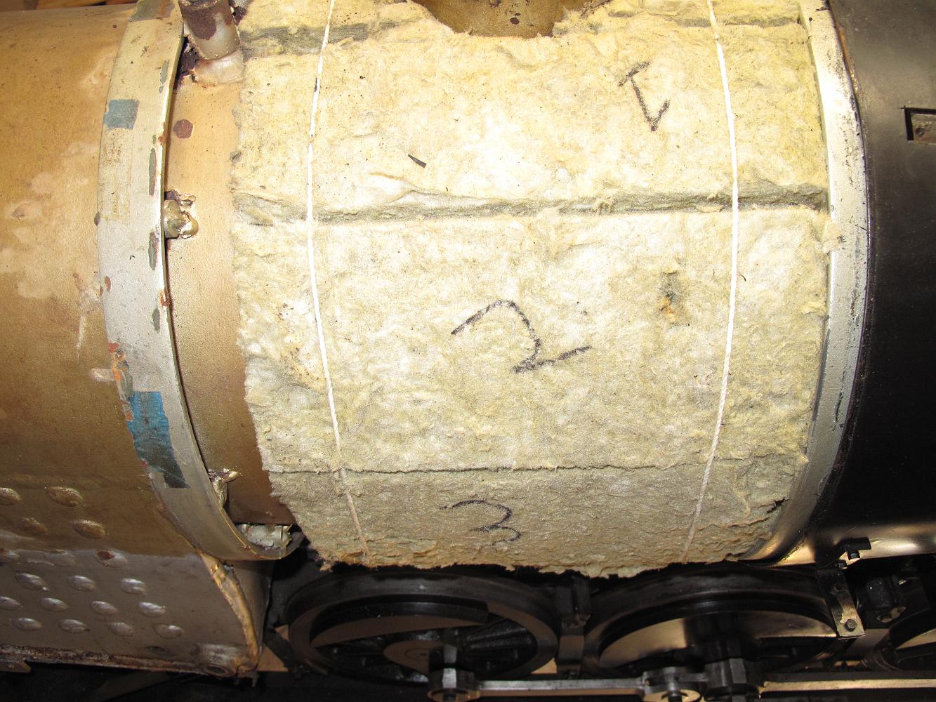
21-Dec-2021 More jacketing removal and the hope I can re-use the insulation.
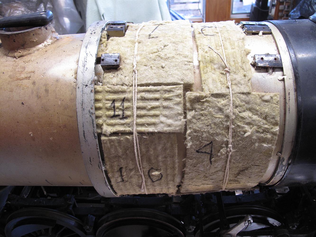
21-Dec-2021 More jacketing removal and the hope I can re-use the insulation.
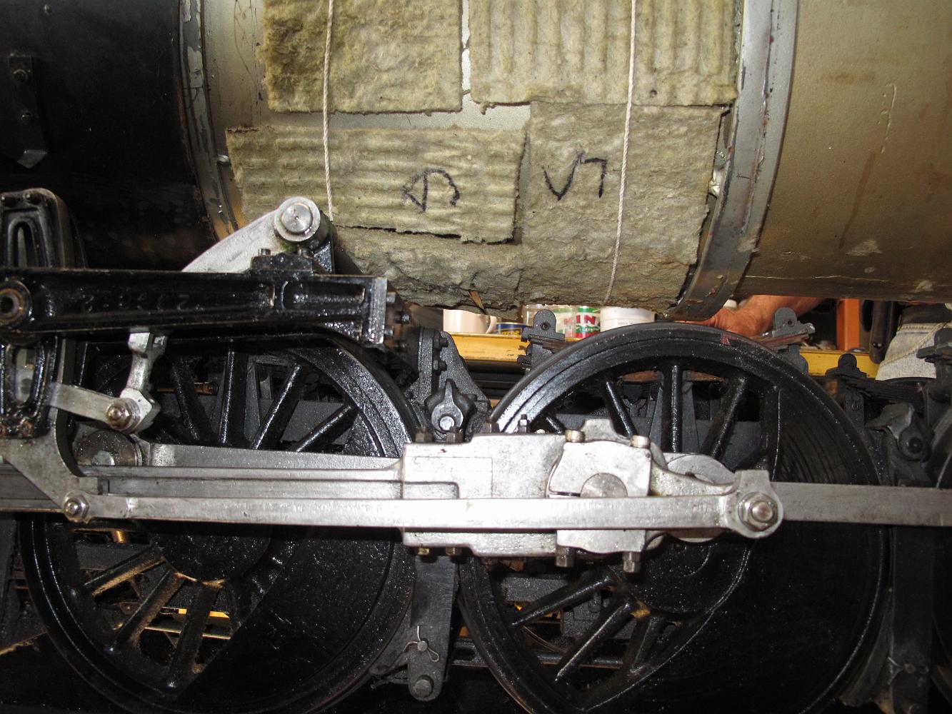
21-Dec-2021 More jacketing removal and the hope I can re-use the insulation.
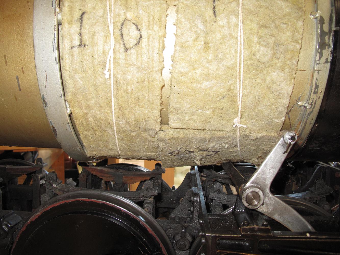
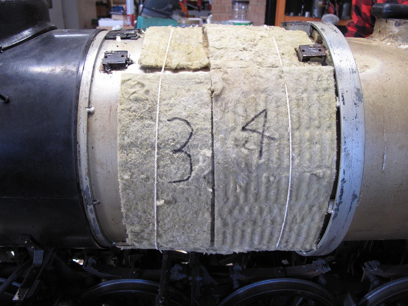
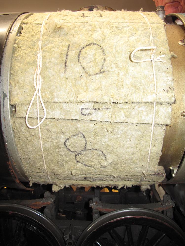
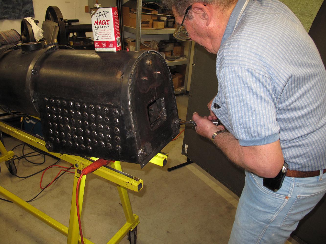
21-Dec-2021 We start the process of stripping the boiler down to the shell for replacement. I'm happy to find the rockwool insulation in pretty good shape.
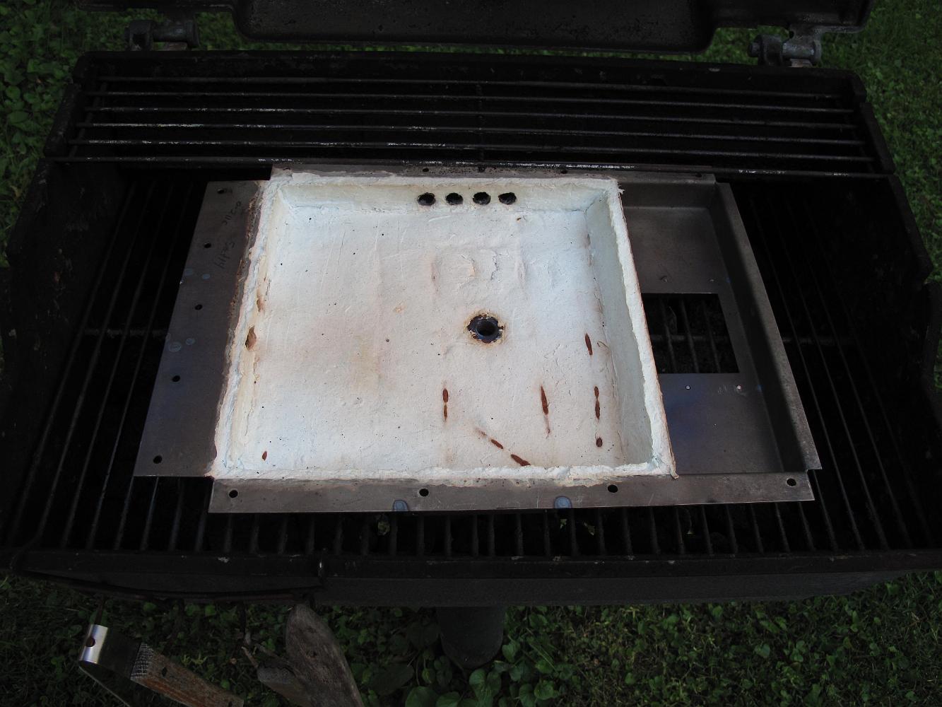
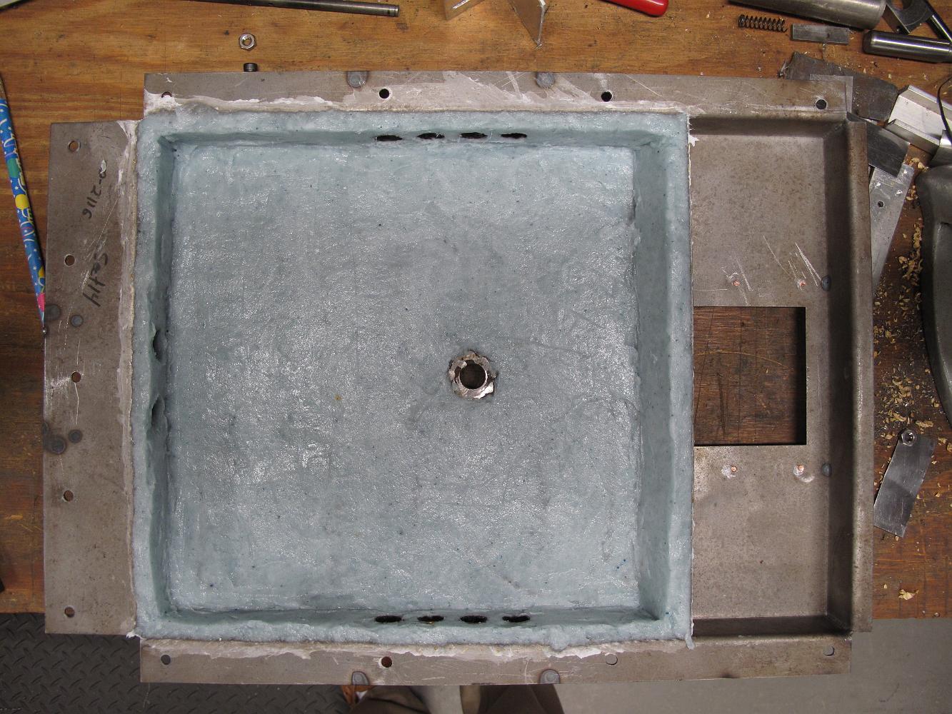
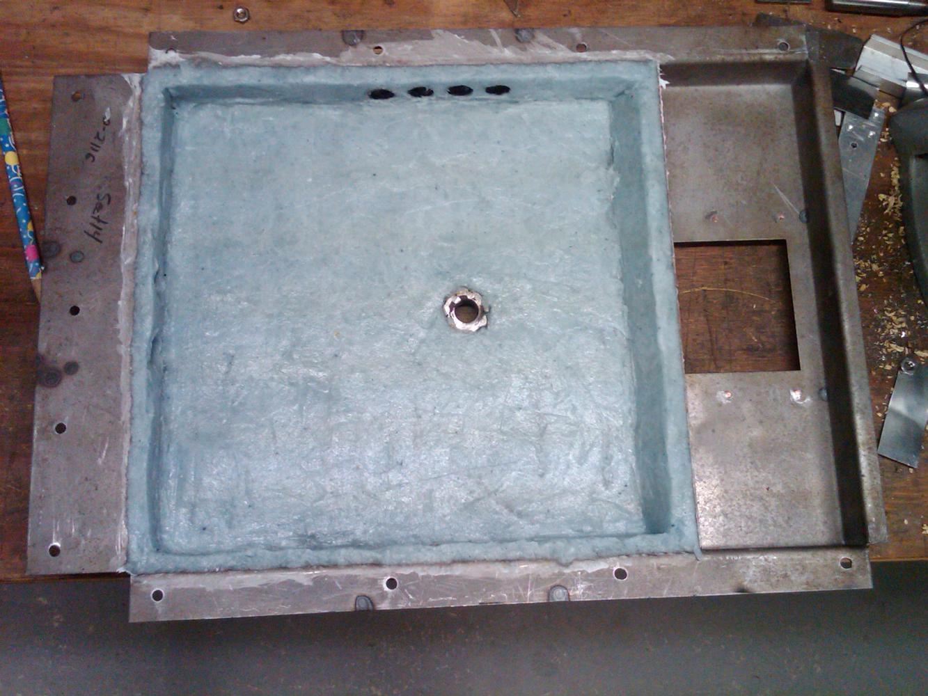
11-May-10 Here is the fire pan baking on the grill. I thought the fiber reinforced refractory cement would air dry, but this morning I found it uncured and…
I'm pretty happy with how it turned out seeing how this was my first time ever working with this cement. And it only took me an hour for this job. Yes, the…
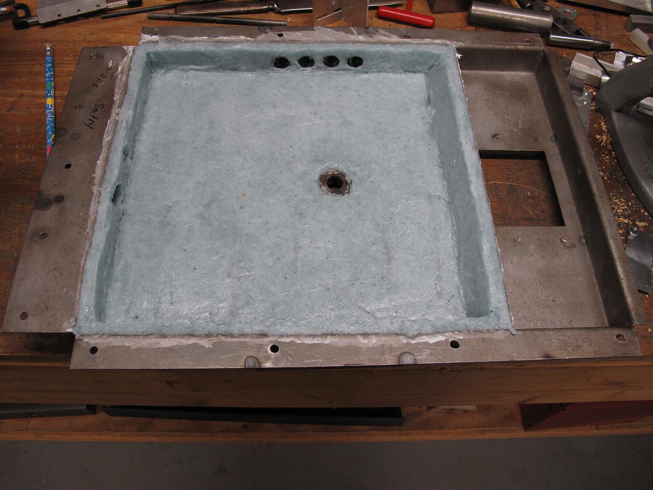
10-May-10 Oh Happy Day, I finally have the refractory cement in the fire pan! I have been hanging onto this wet, fiber reinforced cement for almost a month now…
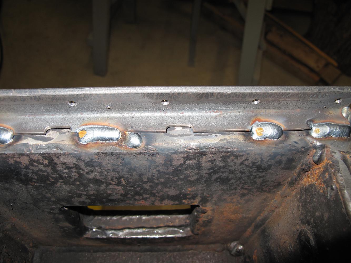
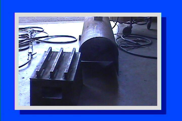
7-May-10 Since the bottom of the boiler is very uneven, and I don't want to drill and tap blind holes into the mud ring, I tack welded 1/4" thick flat stock to…
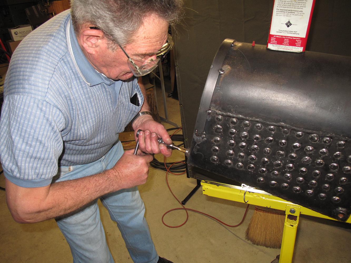
While Bill was making a new Riveting buck, I took some mild steel mending wire and did my best to spot weld it to the pan for the refractory cement would have…
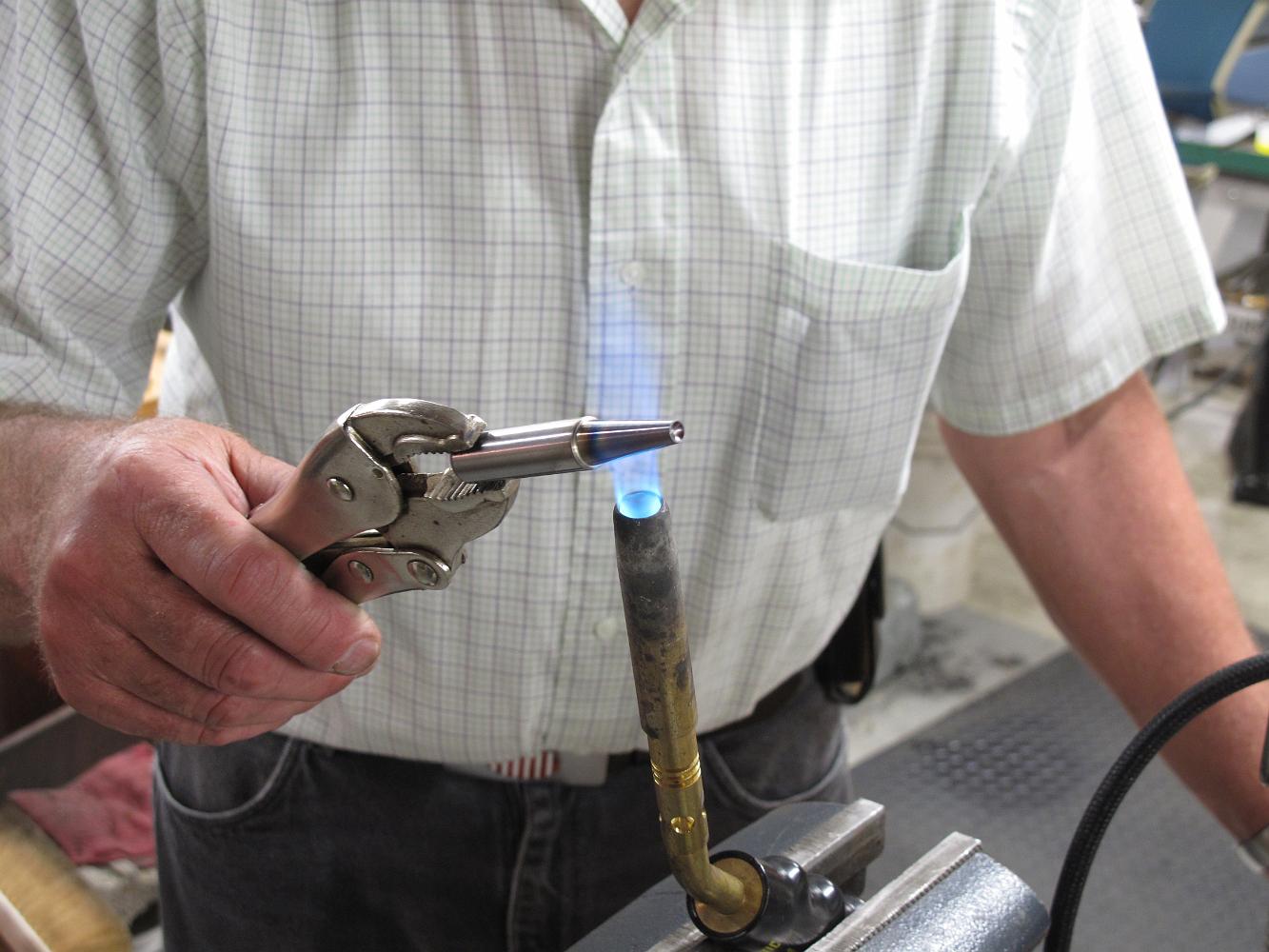
Tempering a new riveting buck after hardening it. This is O-2 oil-hardening steel. We used 40 psi for the riveting gun for the rest of the rivets.
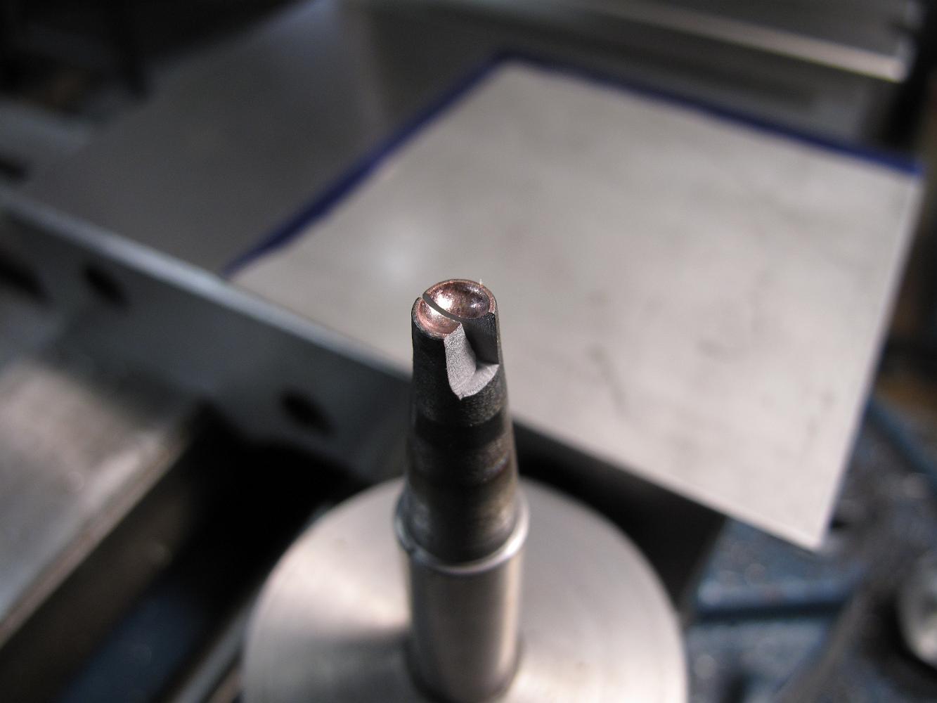
Too much pressure! This is the broken end of my riveting buck which shattered while putting the damper guide bars on. Bill thought 120psi was a 'little too…
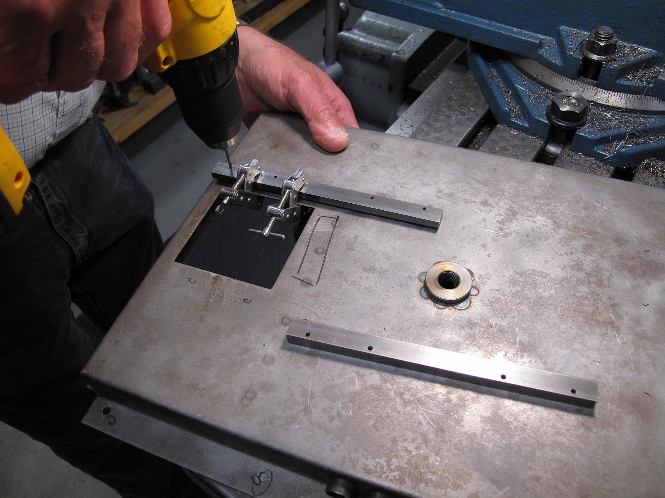
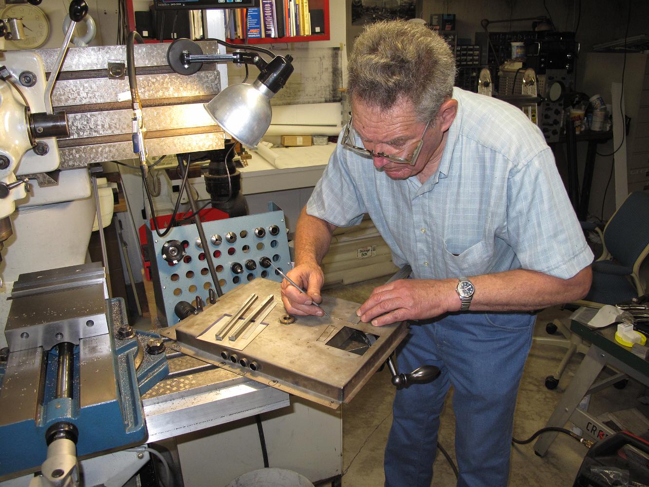
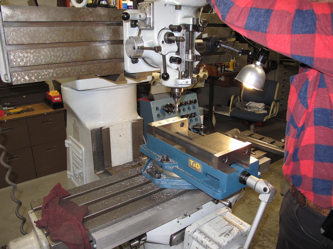
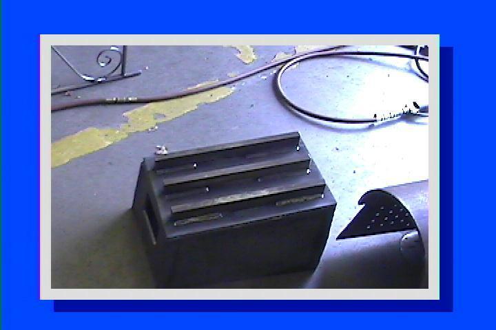
5-May-10 Match drilling the fire pan damper guide bars to the pan. We machined them from solid instead of the build up like the plans call for because this is…
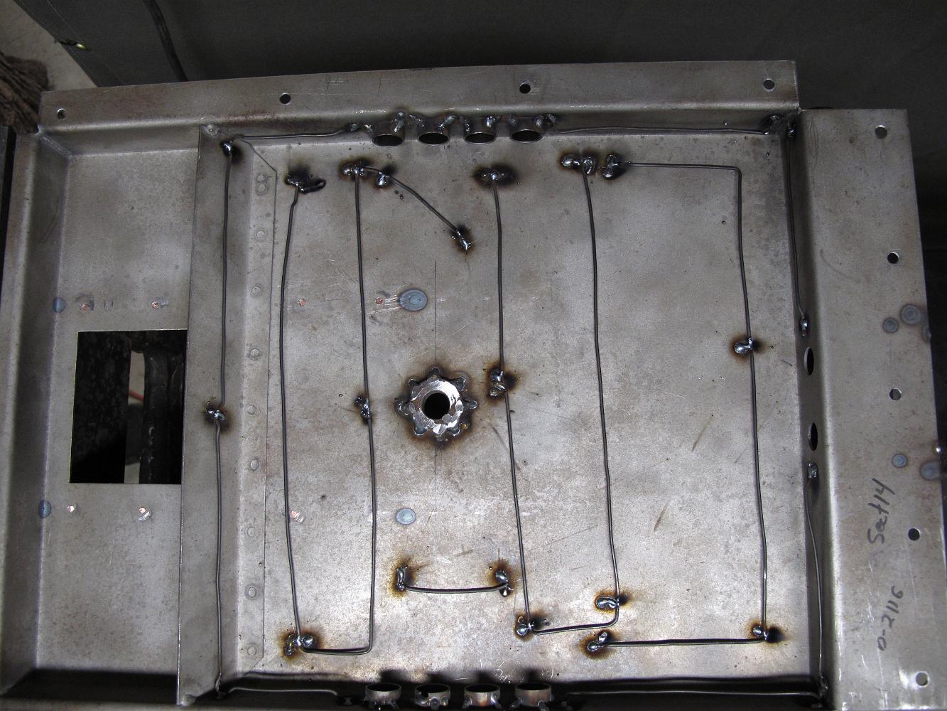
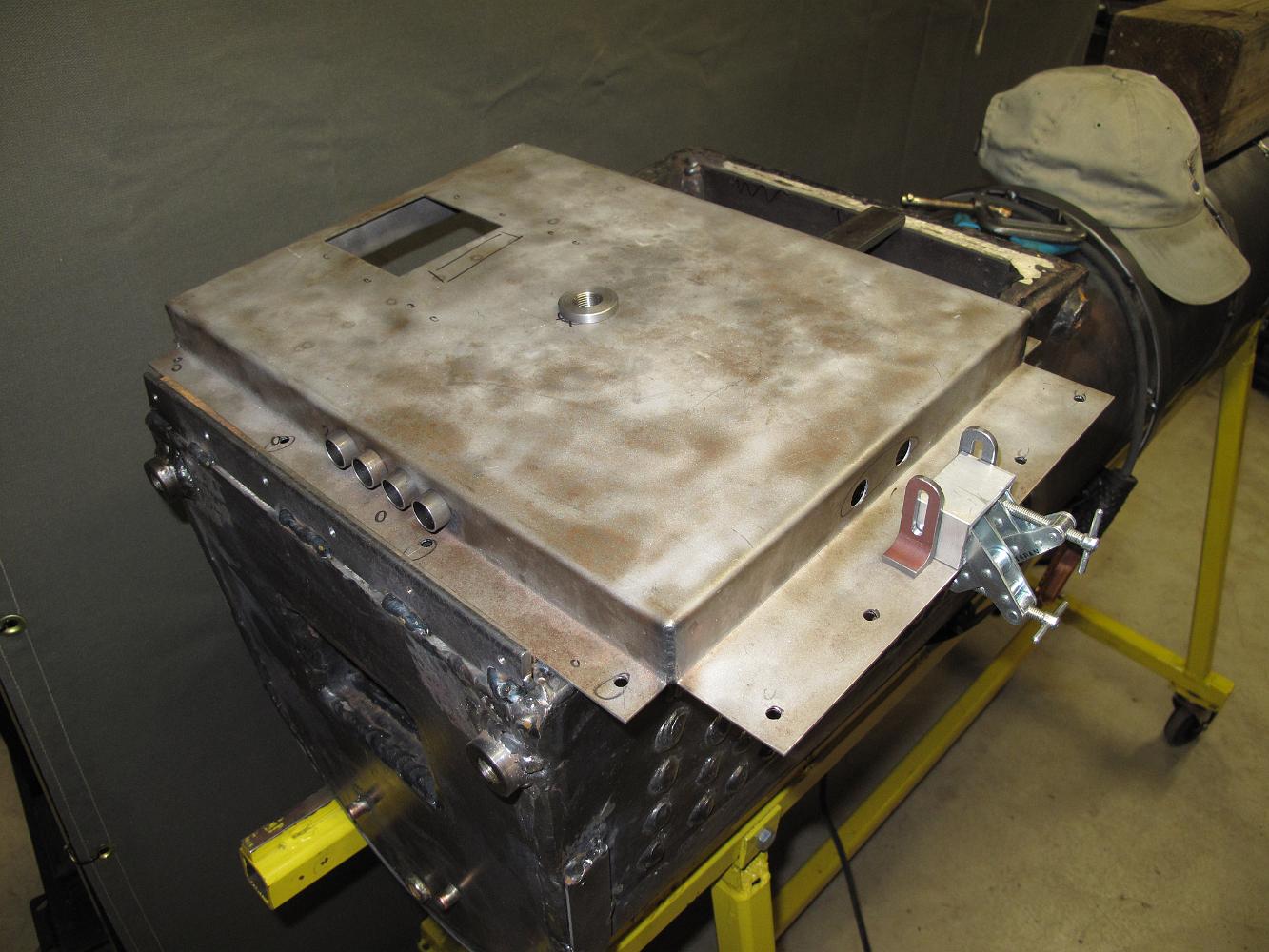
The air intake tubes are spot welded to the fire pan and the burner brackets are ready to be positioned and welded. We used a sizing block to make sure they…
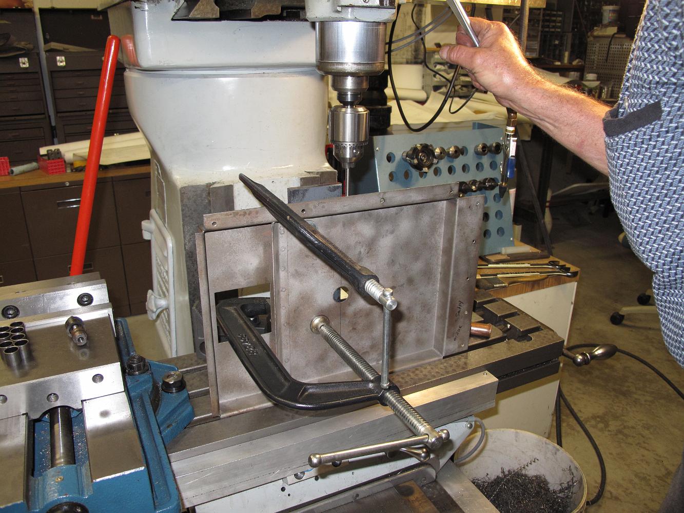
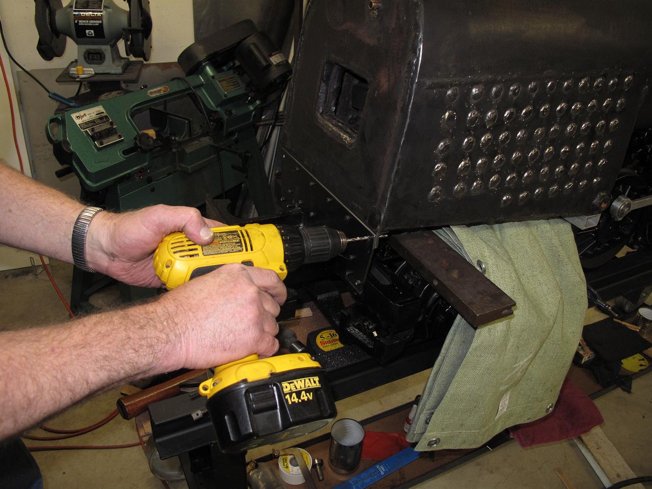
26-April-10 I decide I will weld 1/4" thick bars to the bottom of the boiler to anchor the firepan. I will drill and tap them to match the pan mounting holes…
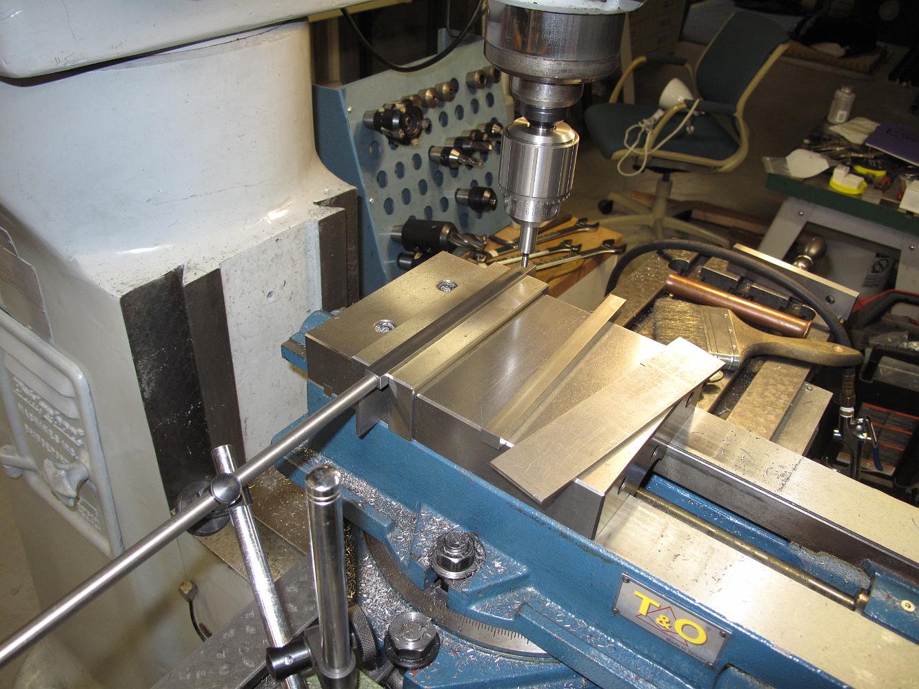
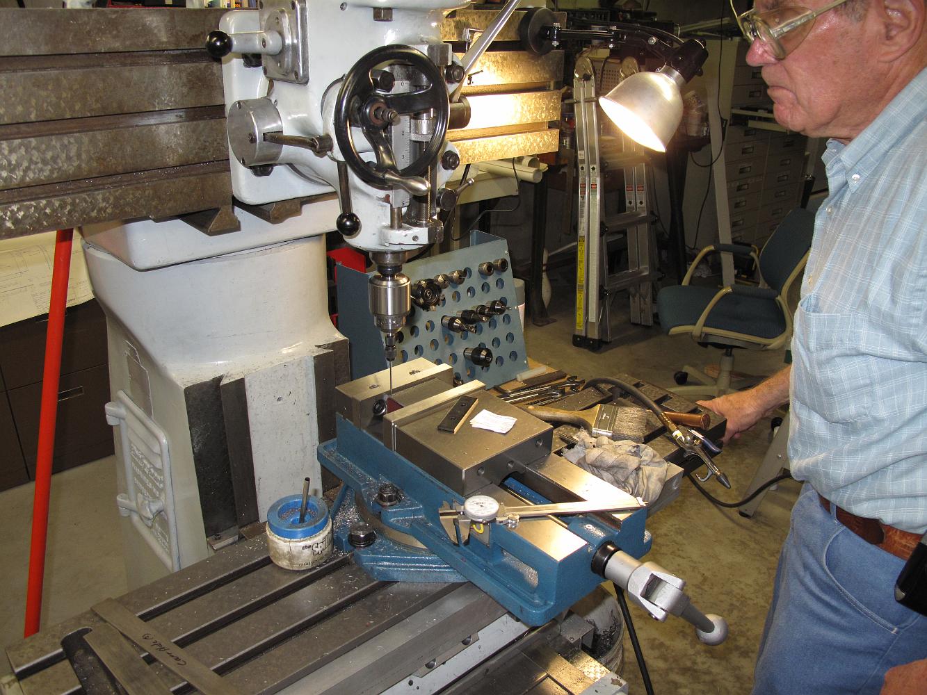
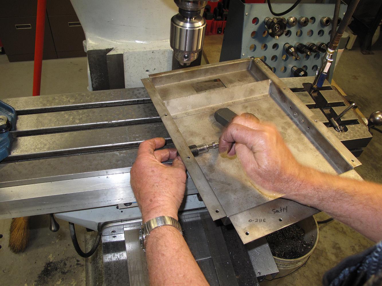
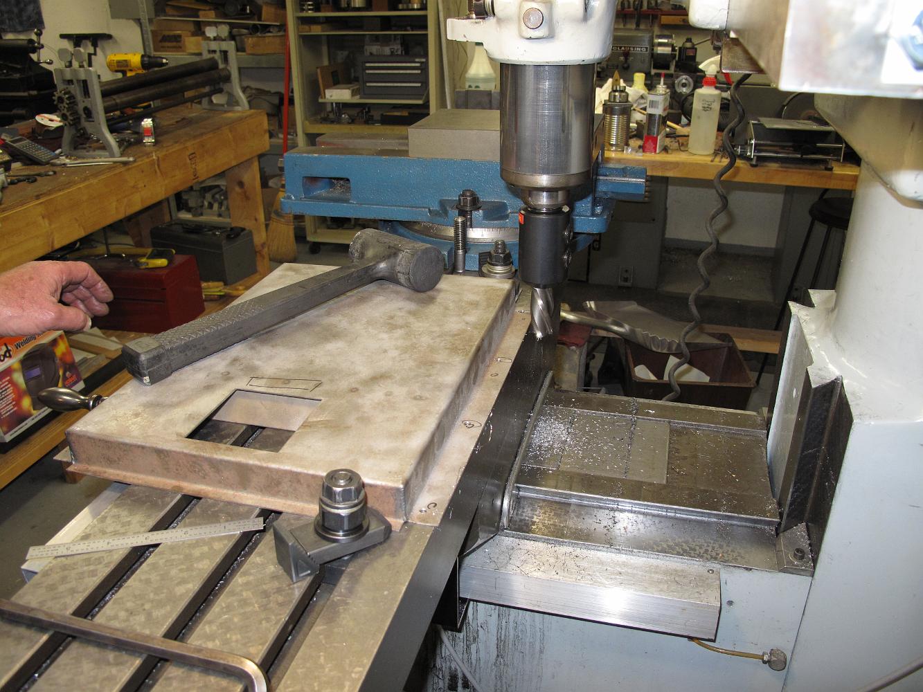
With the pan bolted to table to keep it in one place, we drill two holes for the burners in the end, and finish the holes with the knockout plug cutters.
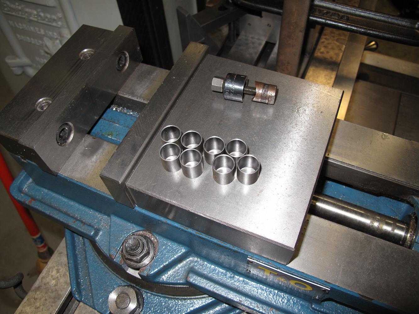
While Bill was putting the holes in the pan, I chucked a piece of 5/8" steel tube in the lathe and turned out eight air intake tubes. In the background you can…
21-April-10 We switched back from working on the Freight Elevator to the firepan because I acquired some wet refractory grout to line the pan with -- only the…
24-Mar-10 Once again I have to thank the generosity of others to have the right tool when needed. Here we are trimming the fire pan width to fit the actual…
Here's one of those 'get around to it' tasks. While we had the boiler upright, we needed to cut the dry pipe down a little. As delivered there was only 1/16"…
24-Mar-10 One week later with a new tap wrench and new skip tooth pipe tap, the holes are threaded quickly and easily. So easy in fact we had to check to see if…
16-Mar-10 You can see both cleanout bosses here. I did not have a "Straight" handle style tap wrench large enough for this reluctant tap, so we tried to use a…
16-Mar-10 After welding two more cleanout bosses on the back of the boiler, Bill tries to tap the 1/4" NPT hole. Even with an oversized hole, a new cobalt…
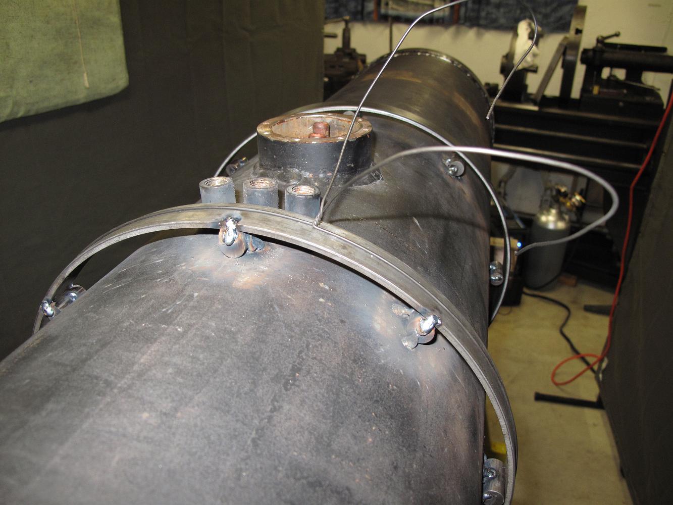
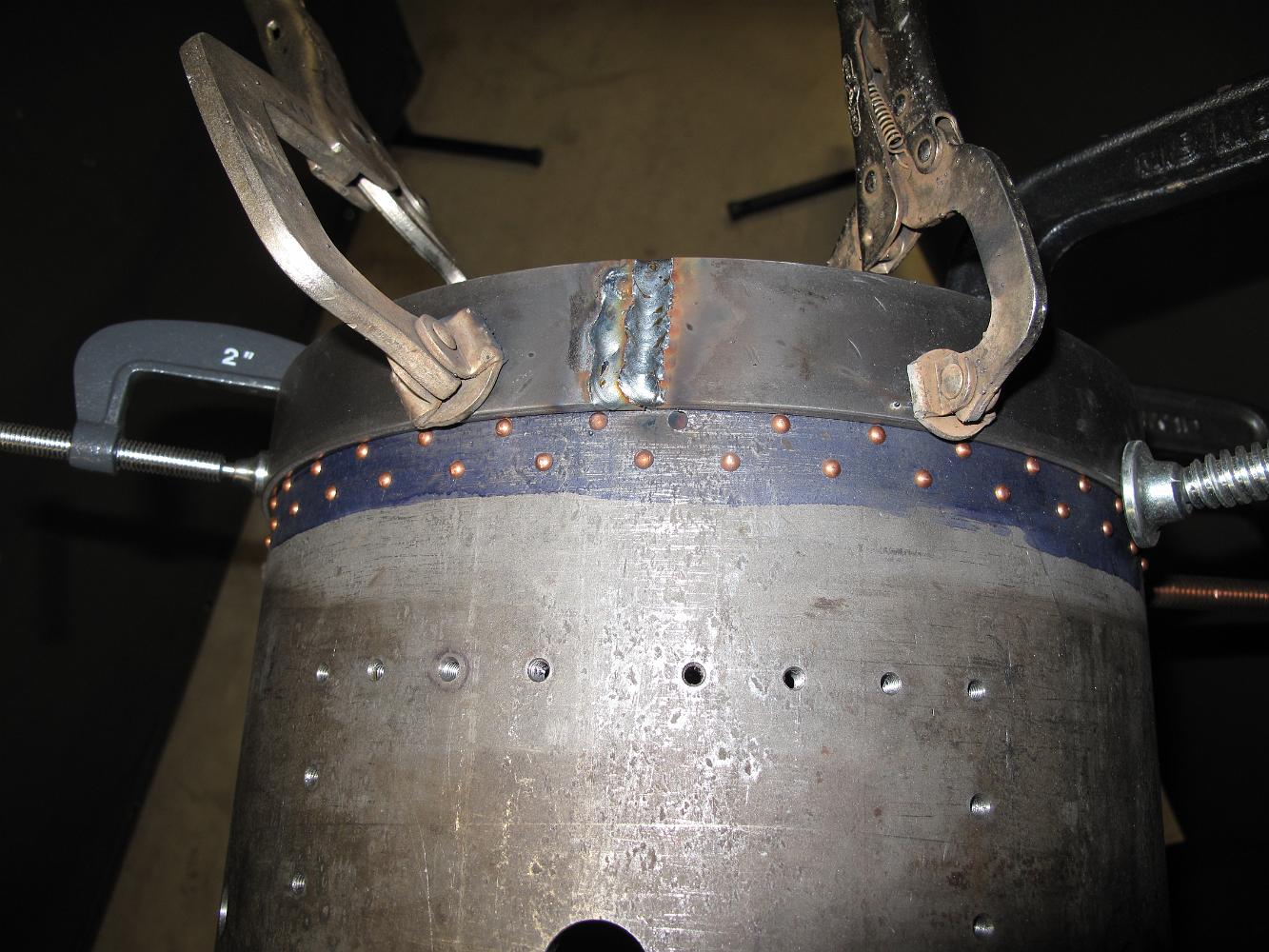
10-Mar-10 The boiler with four rings finished, next to the backhead band. The smokebox mounting ring doubles as the jacketing mount band.
10-Mar-10 We rolled the boiler band mounts, slipped them over the boiler and used bailing wire ('Ford wire' said Bill) to squeeze it down for tack welding. We…
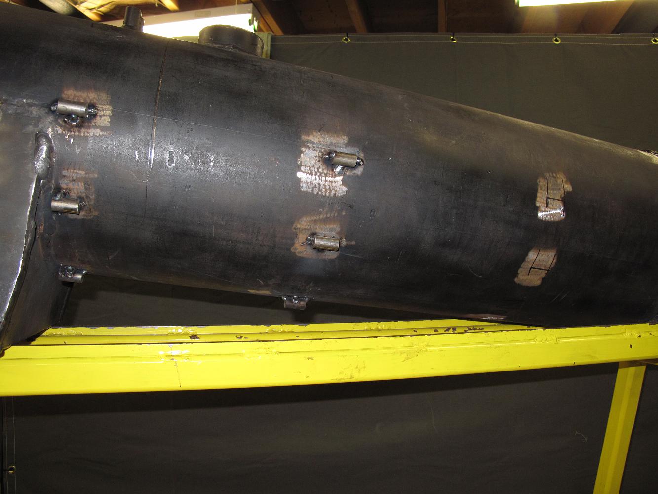
24-Feb-10 We decided to weld the boiler mounting bracket to the bottom of the boiler instead of bolting it like the print calls for. I didn't want to grind all…
17-Feb-10 After considerable effort to remove the smokebox from the boiler thanks to the now Press Fit boiler band (instead of a slip fit), we prepare to finish…
Match drilling the rear boiler support bracket. We had to remove the wood blocking holding the boiler up to install the support bracket. Using machinists jacks…
Here's one of the blueprint mysteries: How do you bend a 3/4" angle 3/16" thick to a 7 degree angle?? I don't know how you hold this small bracket to bend it…
13-Feb-2010 Machining the rear boiler support bracket plate. After waiting 5 weeks from my metal supplier, I finally have some stock to work from. First we laid…
10-Feb-10 The rear boiler mounting bracket has been fabricated, temporarily installed and the angle bracket clamped in place to be tack welded.
6-Feb-10 The boiler temporarily installed on the chassis, front smokebox mounting ring welded to the boiler.
Strips of metal used to fill the gaps between the out-of-round boiler and very round smokebox and mounting ring. You can tell I'm not an experienced…
6-Feb-10 The first mounting of the boiler on the frame. The orange strap is keeping the boiler tight against the smokebox until I can weld the mounting ring.…
Previously, the mud ring on the bottom of the boiler was ground a little bit flatter to better fit the firepan, and the front of the boiler was ground to fit…
My buddy Al stopped by and gave Bill and I a hand. Here we are mounting the smokebox to the cylinder saddle in preparation for the boiler.
Saturday 6-Feb-10. Another wet, snowy day outside means no track work, we retreat to the shop instead! Bill and I drill and tap for eight 10-32 screws to hold…
3-Feb-10 The smokebox to boiler mounting band has been rolled, sized and welded together. We have had to adapt the blueprint plans to the boiler since the…
Bill test fits the band. We are getting close to the right diameter, looks like we need to cut a little more off the ends. This is not the final position of the…
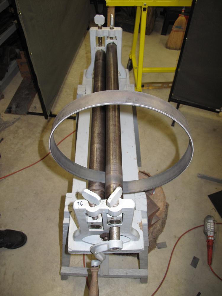
3-Feb-10 My poor aged pinch roller suffers abuse when I roll the 3/16" thick, 1-1/2" wide mild steel. The wooden stand the roll is on wobbled, swayed and jumped…
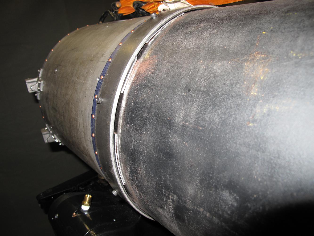
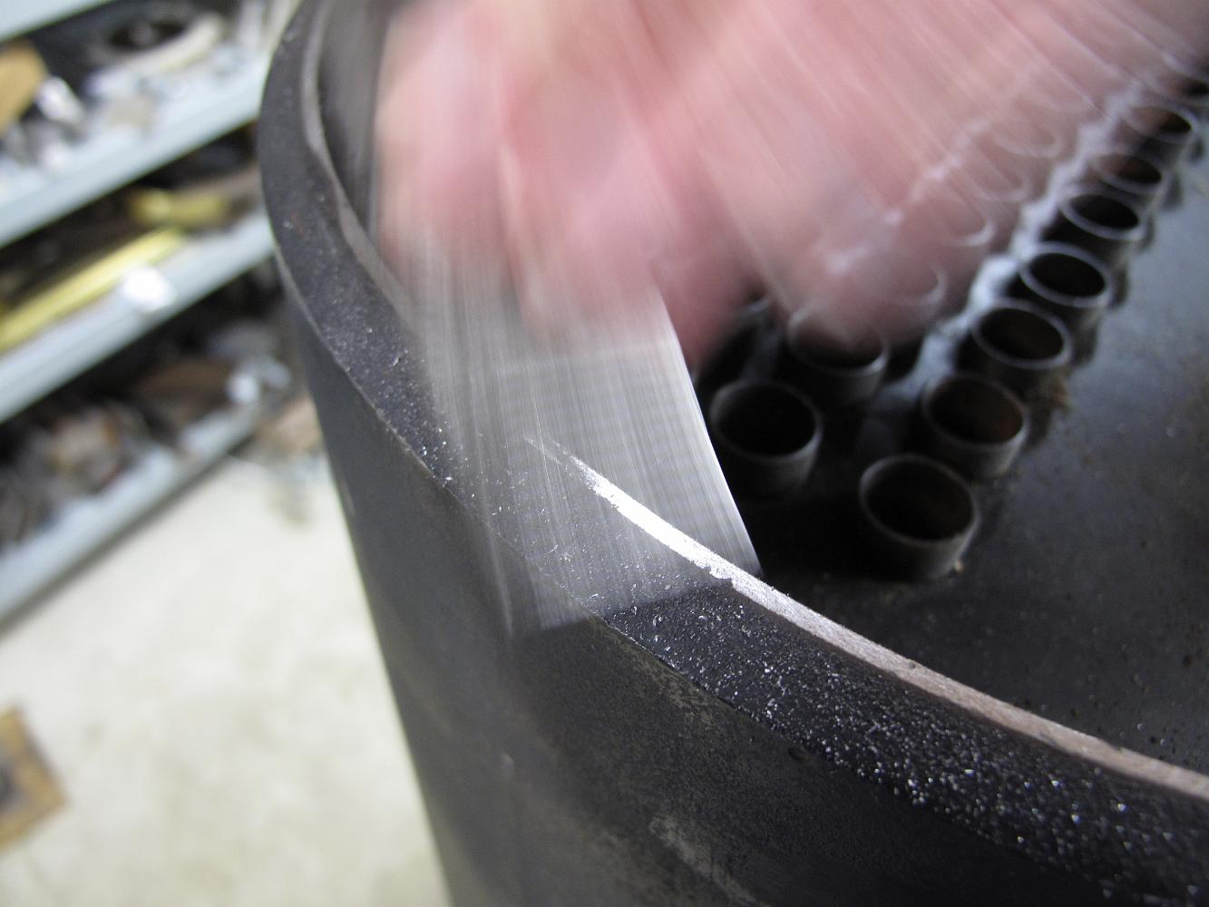
20-Jan-2010. Filing the factory bevel on the end of the boiler. The bevel is put on the pipe at the time of manufacture so the welders (when joining it to…
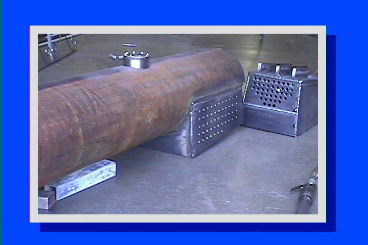
A look at the bevel edge that has to go. Another reason we need a flat surface is the boiler is not actually round, unlike the smokebox. The 12" pipe was cut…
Bill takes a large file to see how much of the factory welding bevel we will have to take off to make the smokebox fit on the end. Conclusion: A lot. Time to…
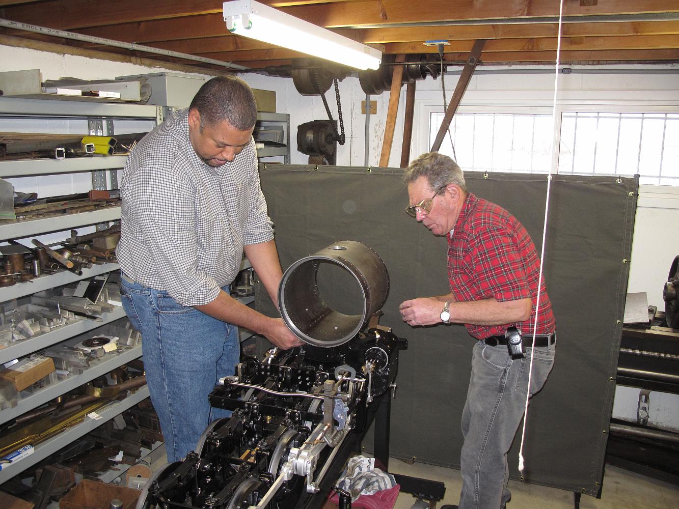
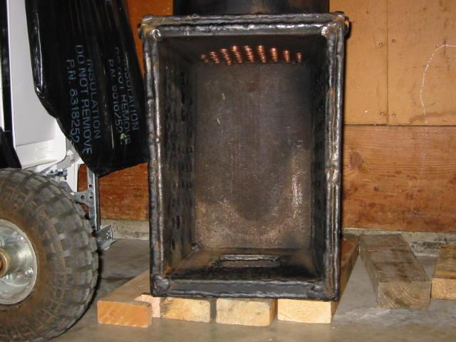
13-Jan-2010. Kind of an odd perspective here, you are looking inside the smokebox. The boiler is vertical standing on the floor and the smokebox is sitting on…
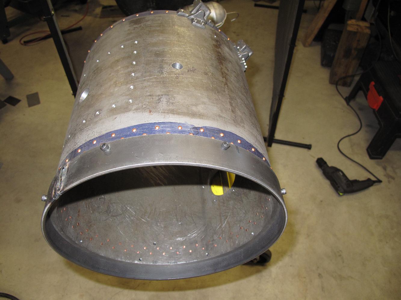
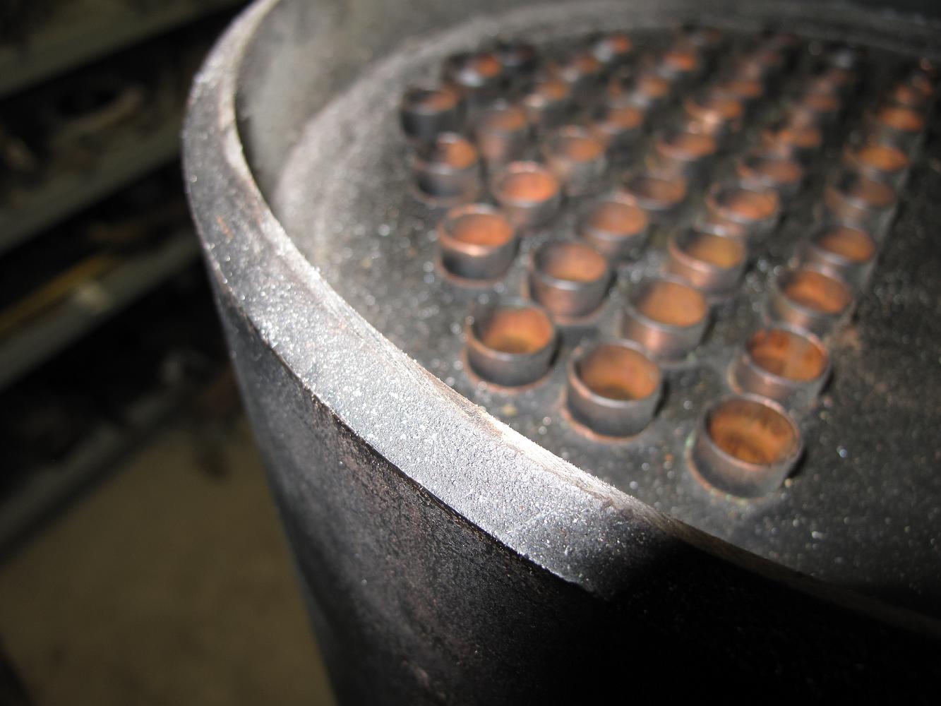
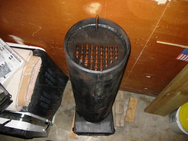
End view or smokebox view of the new boiler. The perspective is a bit strange since the 50" boiler is sitting on the floor leaning against the wall and I had to…
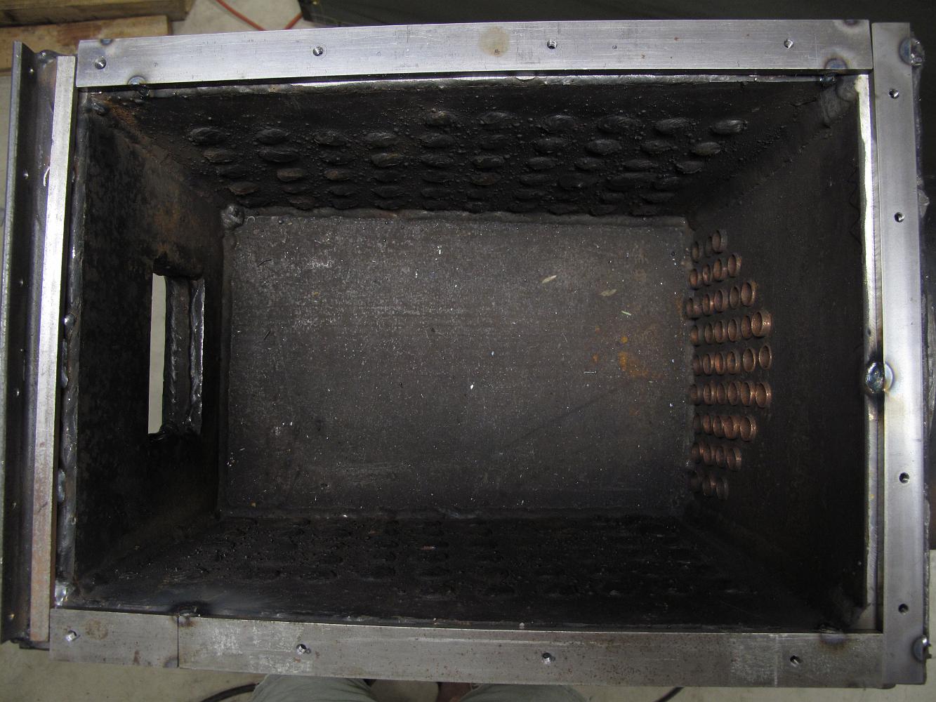
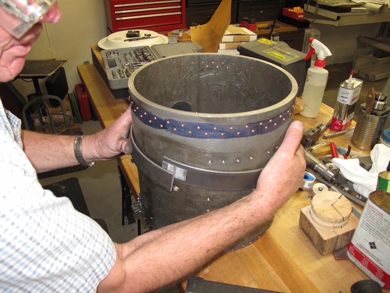
Bottom view of the big firebox. Inside the firebox you can see the copper ends of the flue pipes, called flues, these will allow the coal smoke to pass through…