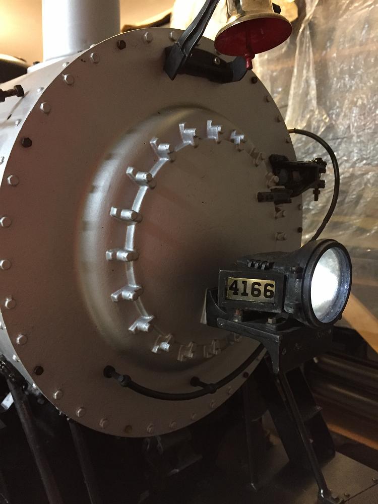
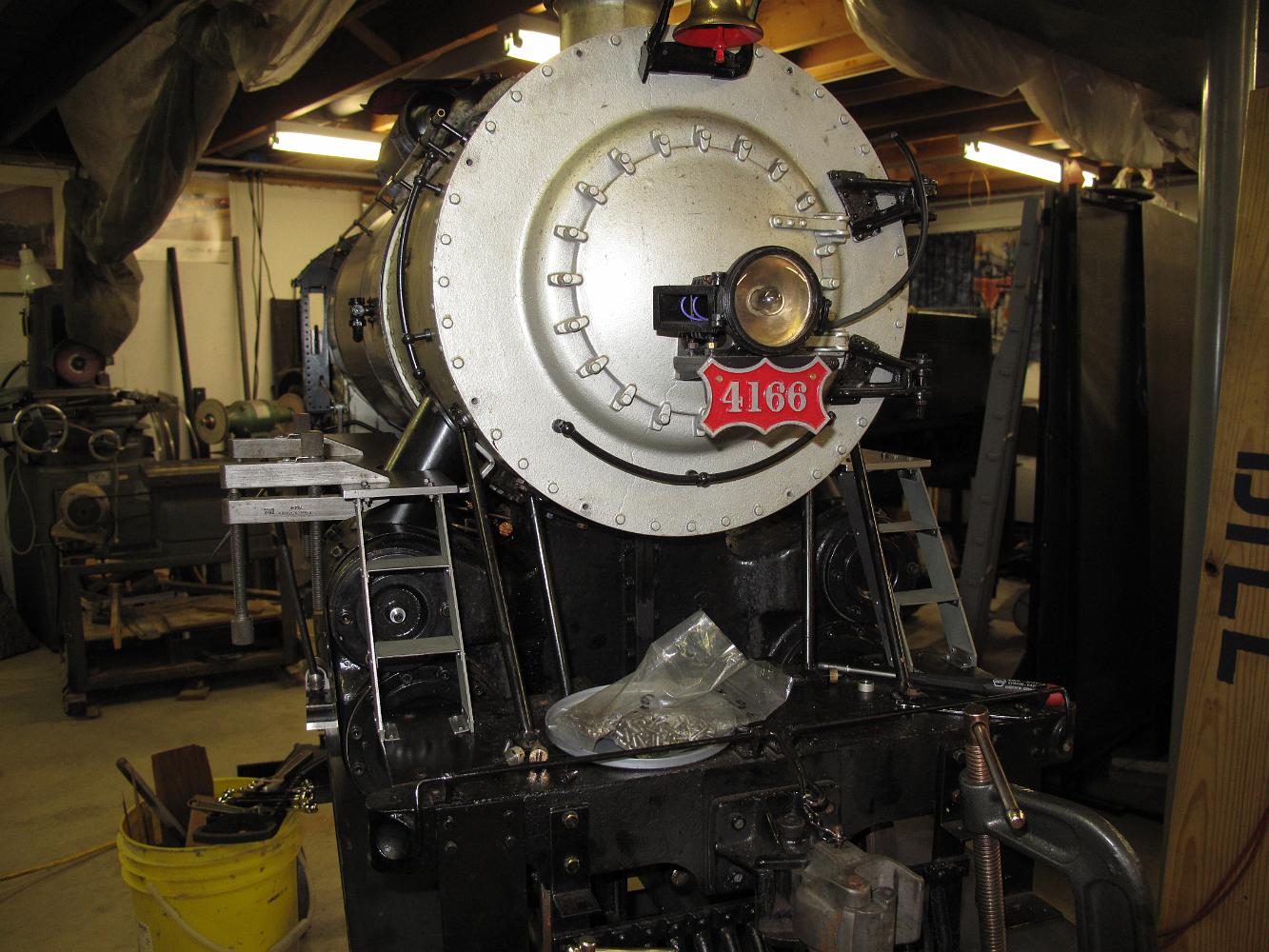
2019-04-16 - LED lights are wired up to illuminate the headlight number boards
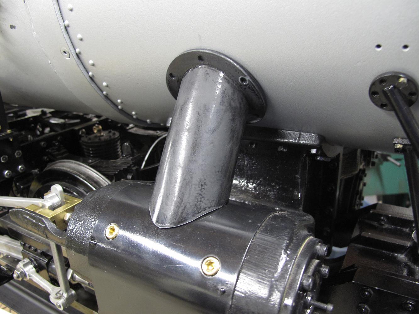
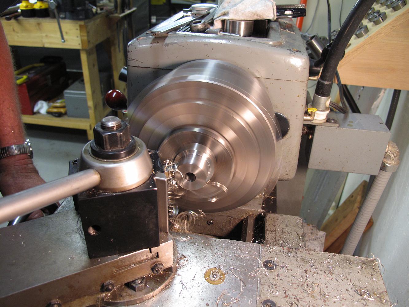
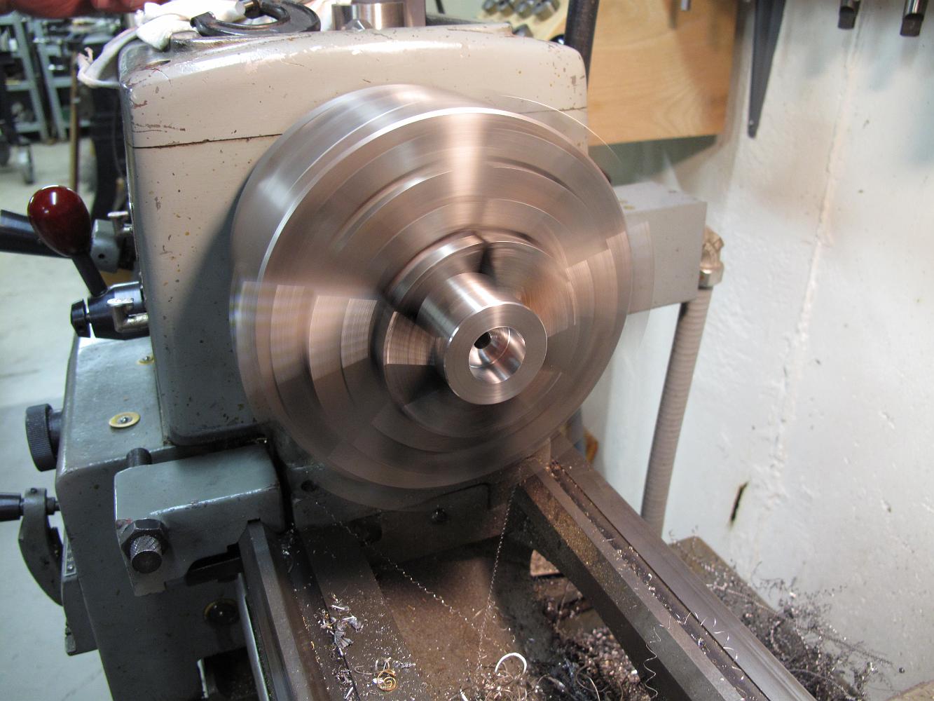
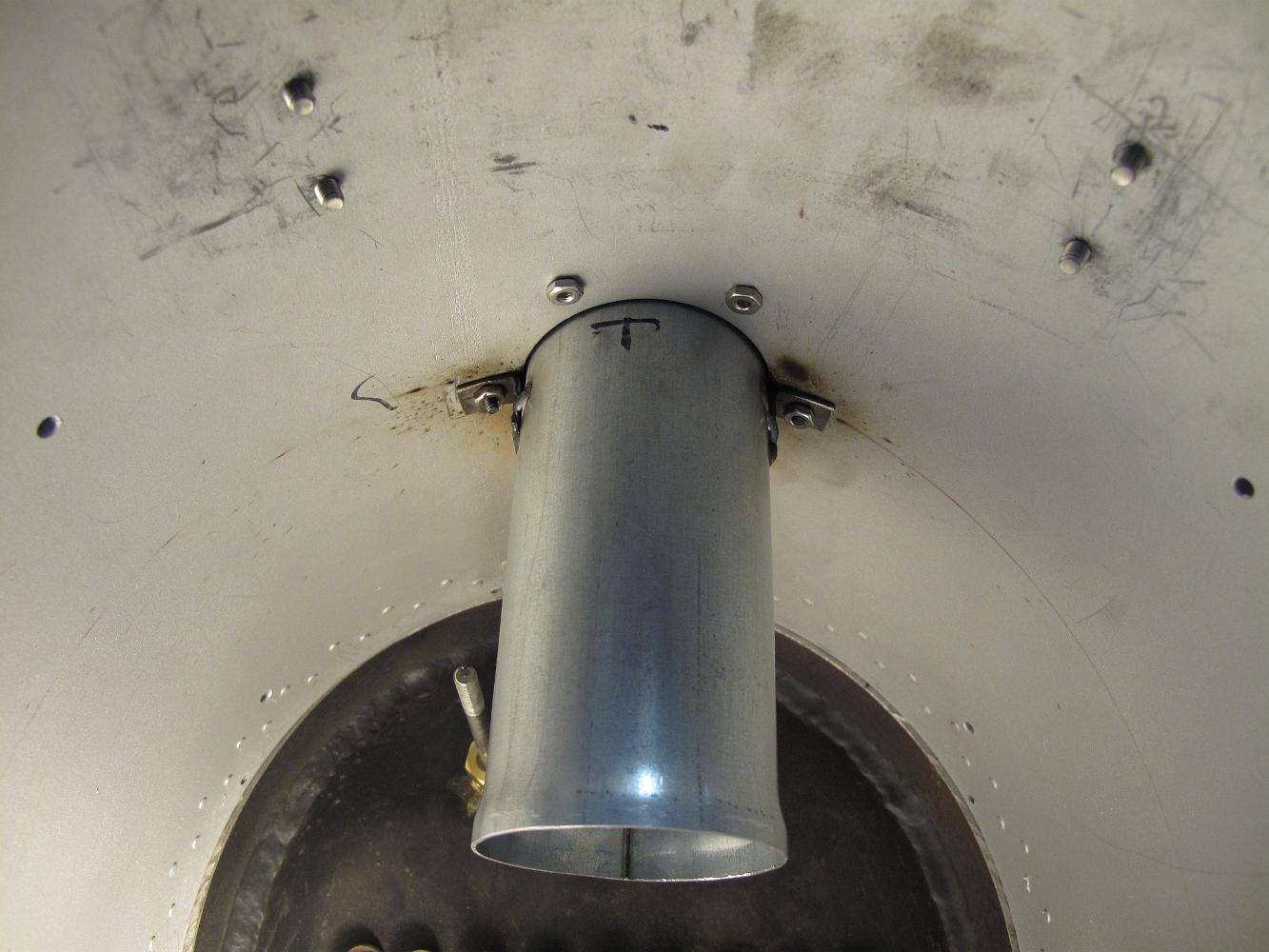
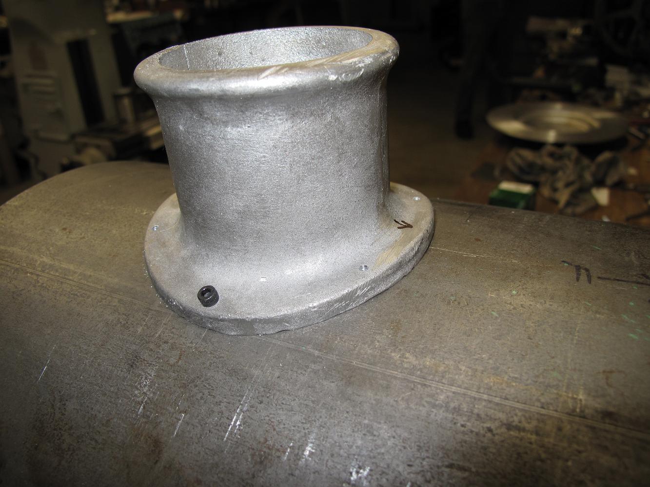
29-Jan-2019 Stack modification after machining, ready for paint.
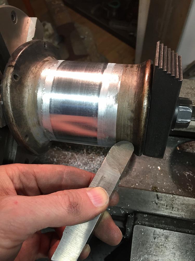
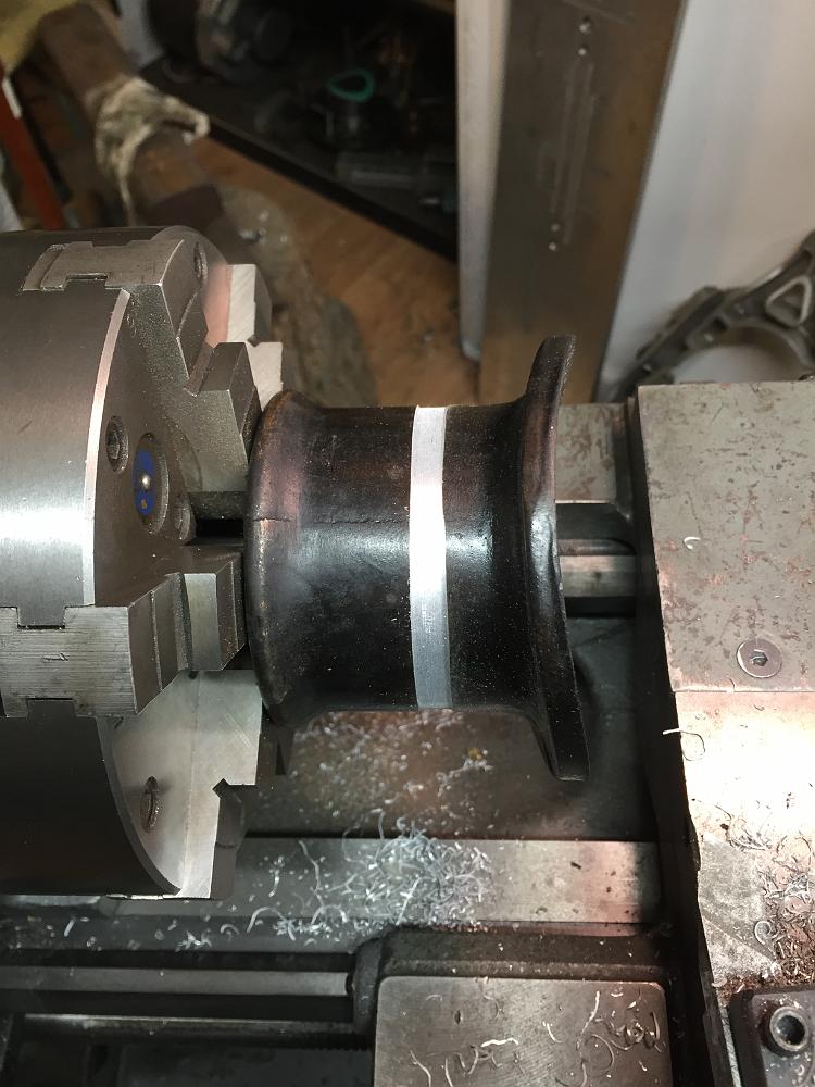
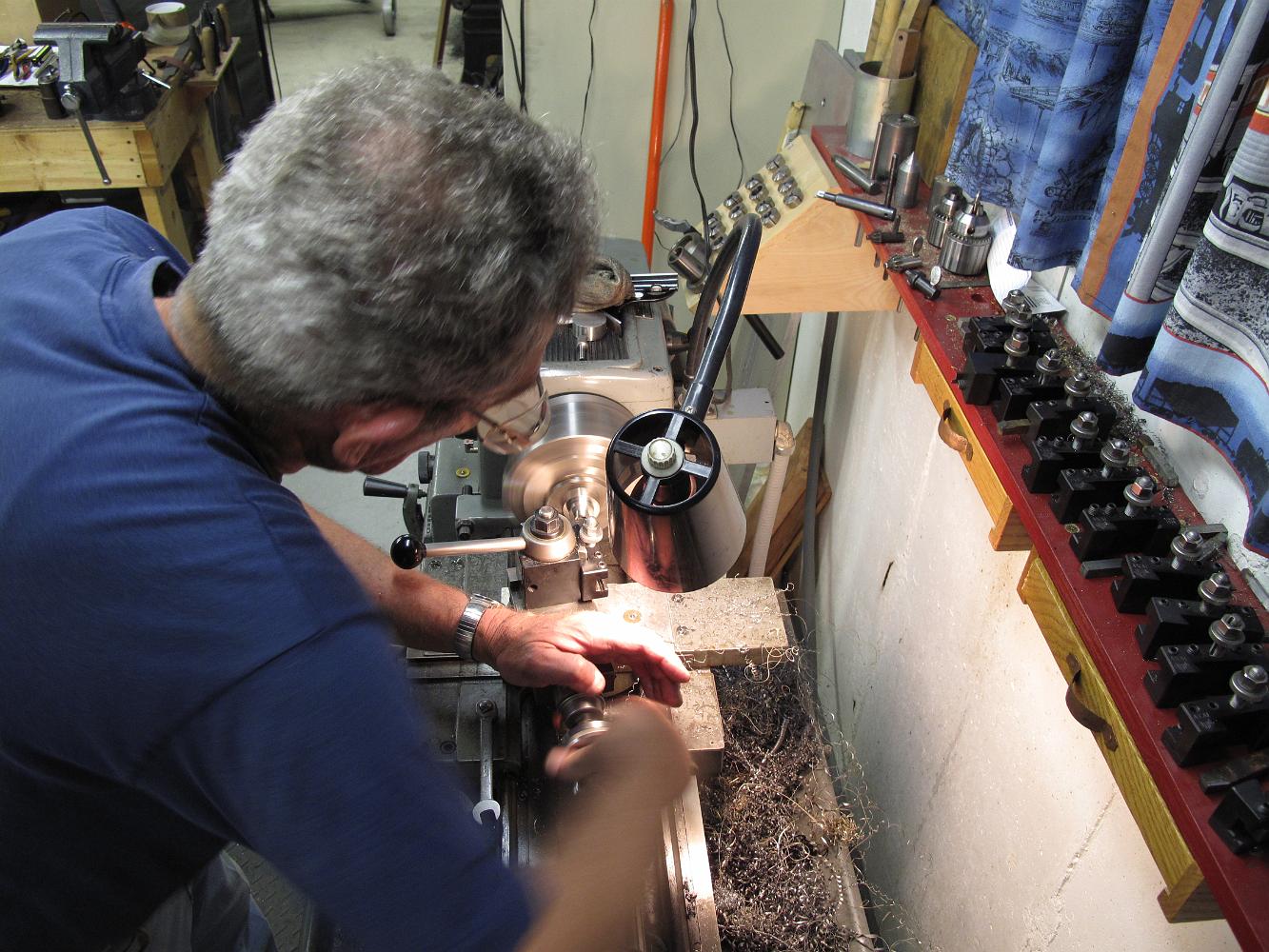
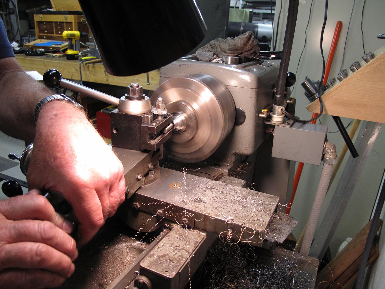
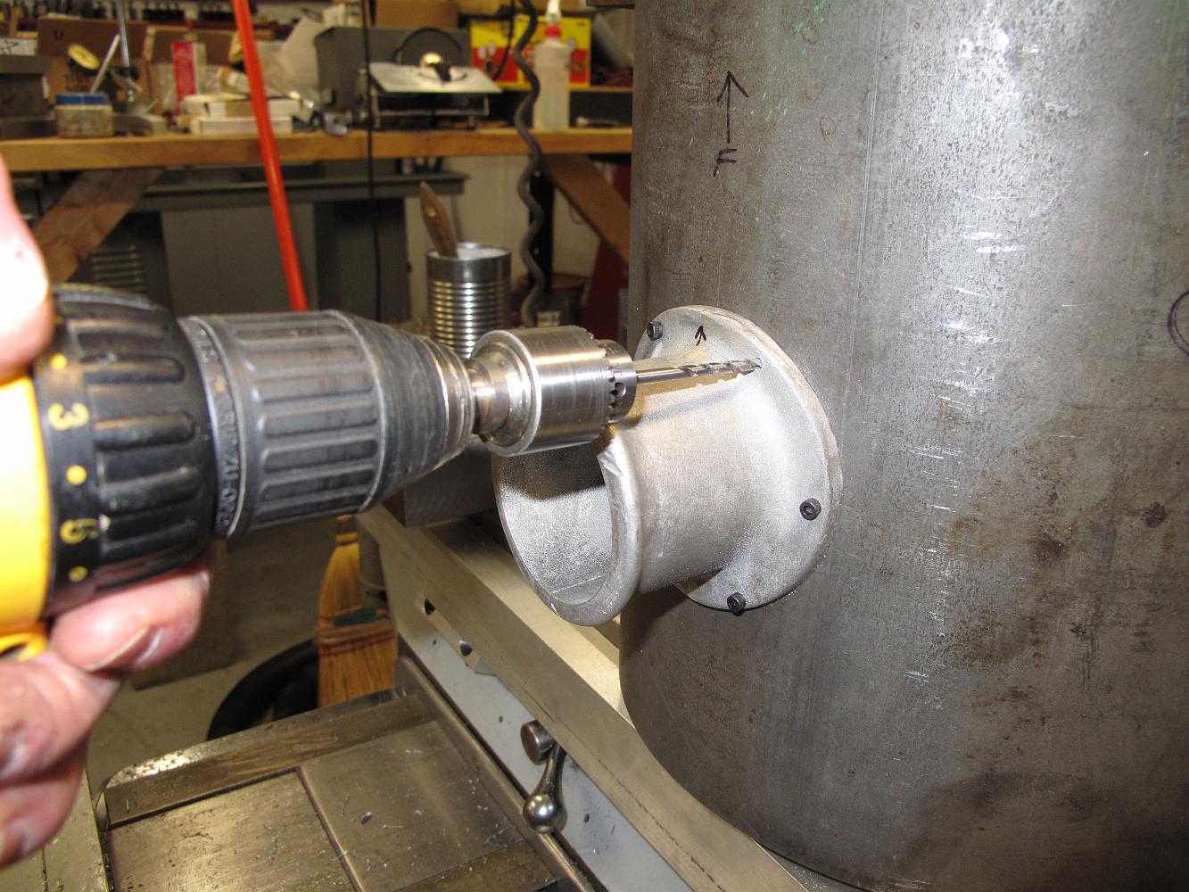
29-Jan-2019 Using a large radius lathe tool, we smooth the weld marks and blend the old casting to the new material.
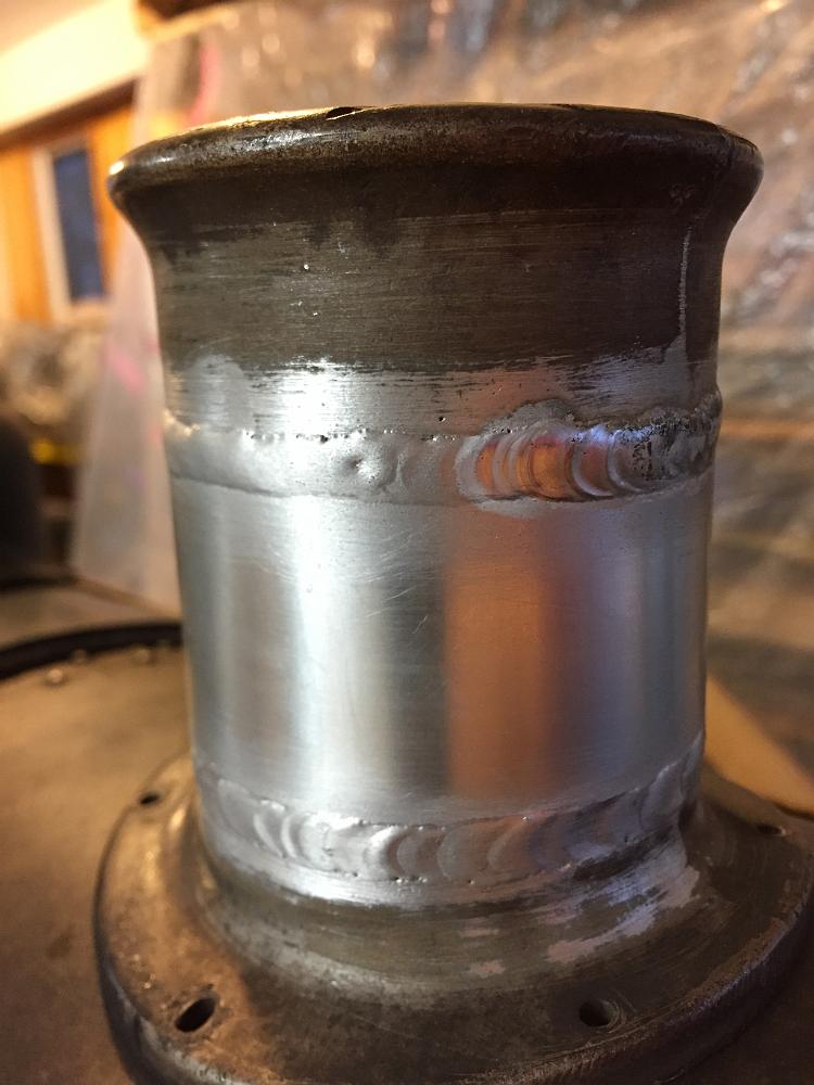
22-Jan-2019 The stack after TIG welding. I am thrilled with the results. Next is to machine the 'fishscales' welding marks smooth.
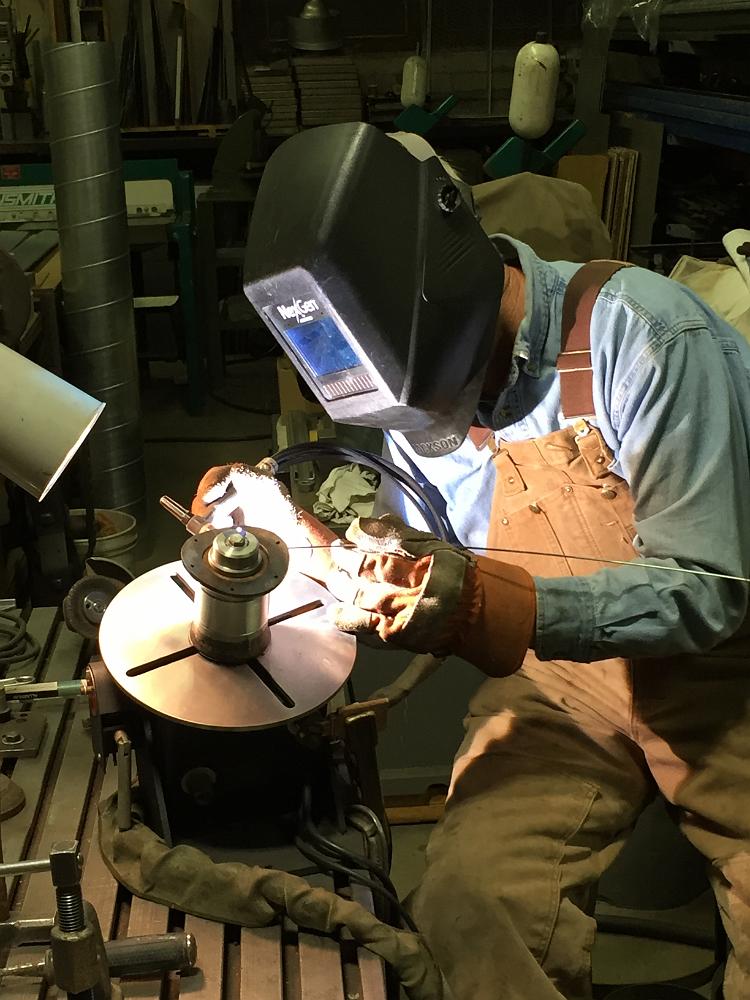
22-Jan-2019 Fellow club member Richard has both the welding experience and equipment to do the job. The aluminum stack casting, with new aluminum spacer in the…
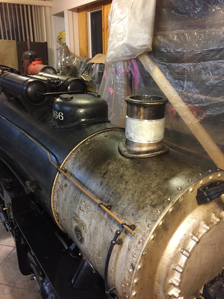
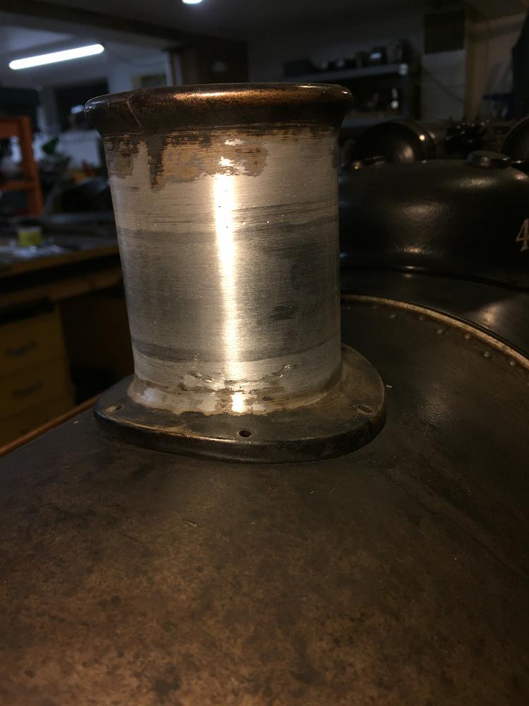
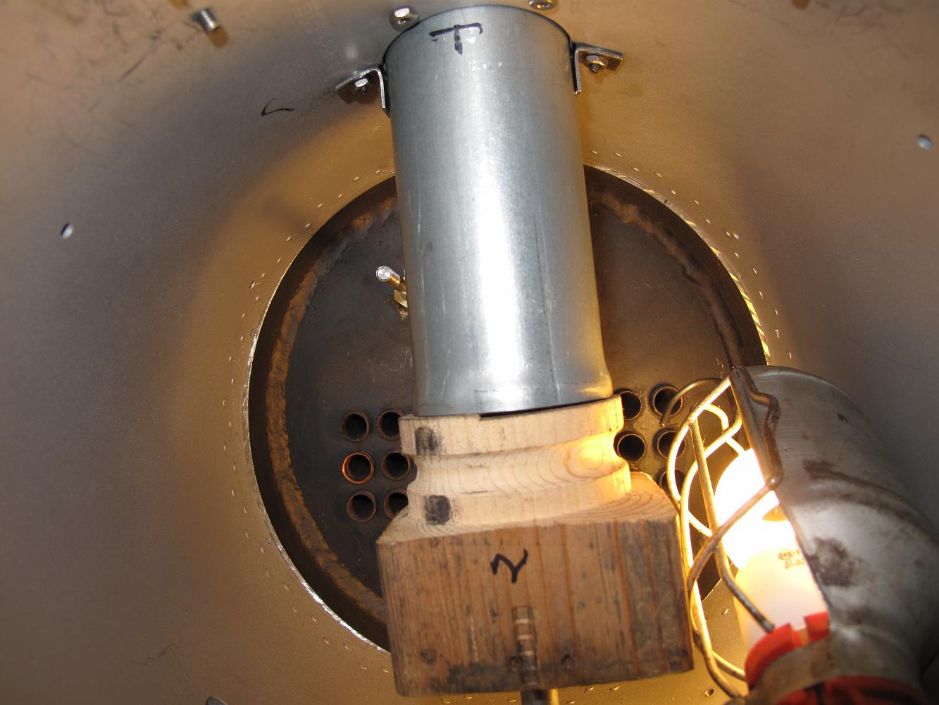
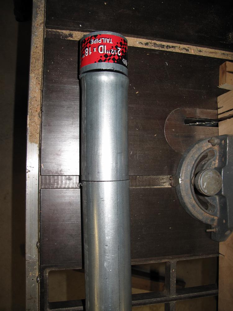
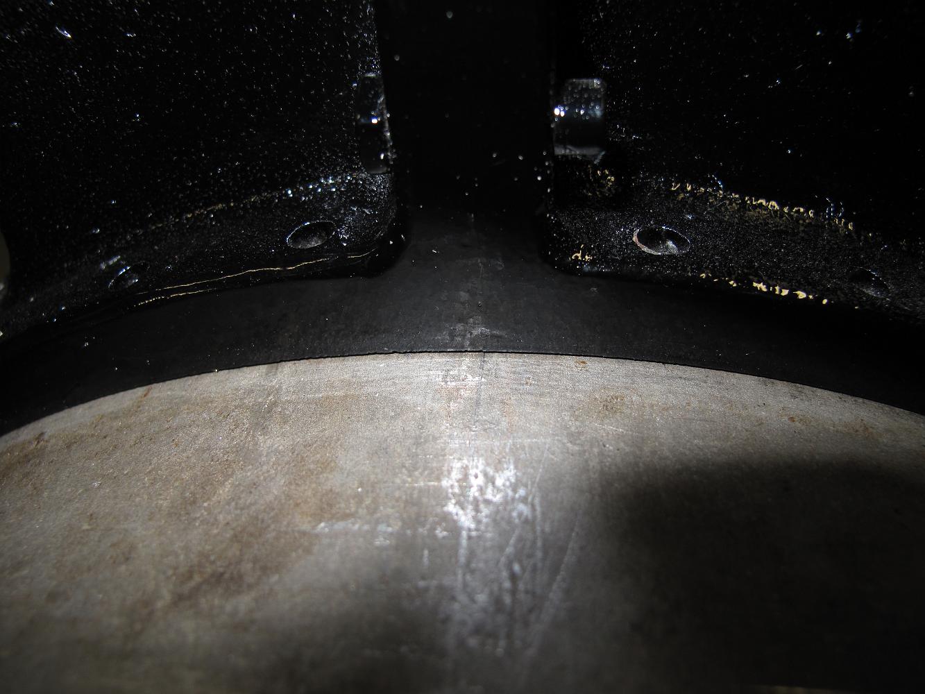
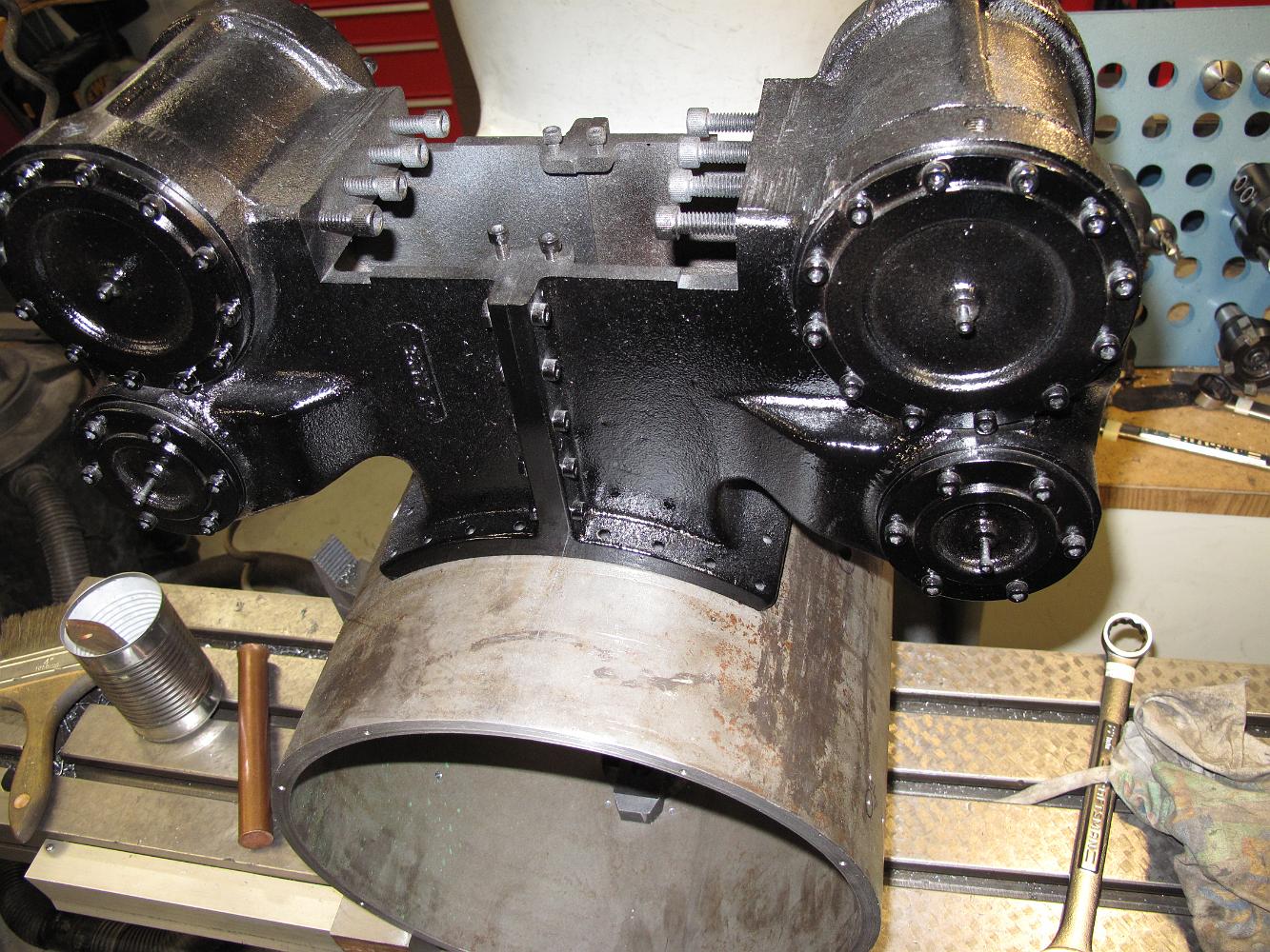
13-Nov-2018 The machined stack spacer test fitted on the engine. Now to figure out how to weld aluminum give the equipment on hand.
13-Nov-2018 After getting comments about the smokestack installed on this Frisco modeled engine being too short, we decide on a plan to lengthen the stack. This…
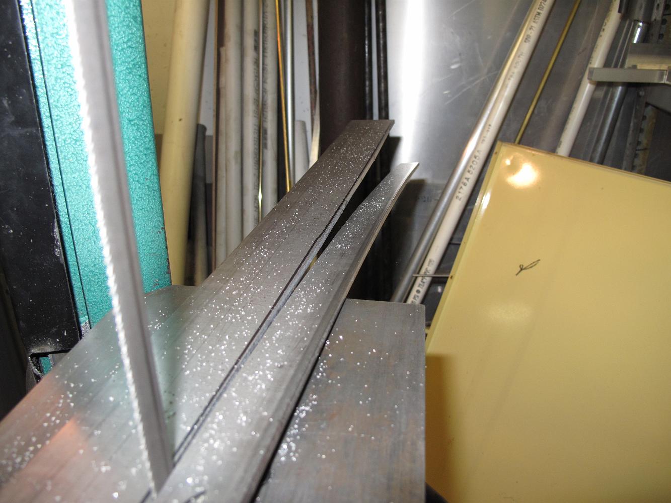
9-Feb-2015 Using the bandsaw to rough cut the rear running board. Cutting a long stip like this releases the internal stresses of the cold-rolled 1018 causing…
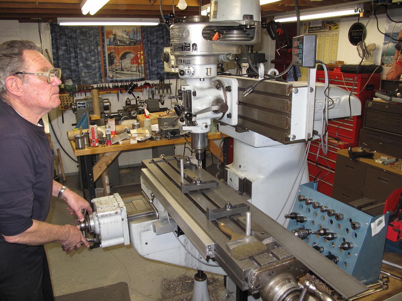
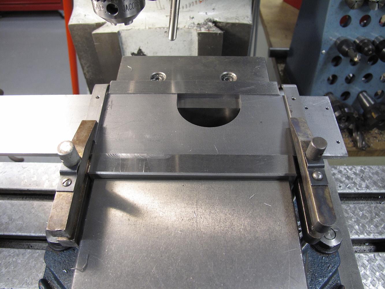
9-Feb-2015 Preparing to finish machine the tapers on the rear running board.
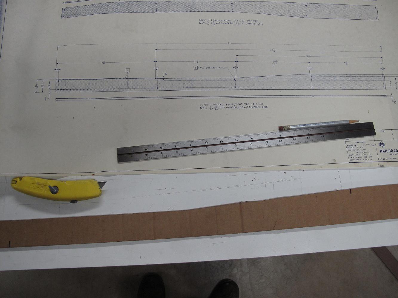
9-Feb-2015 Cardboard template of rear running board. I used it to rough saw cut the stock before machining.
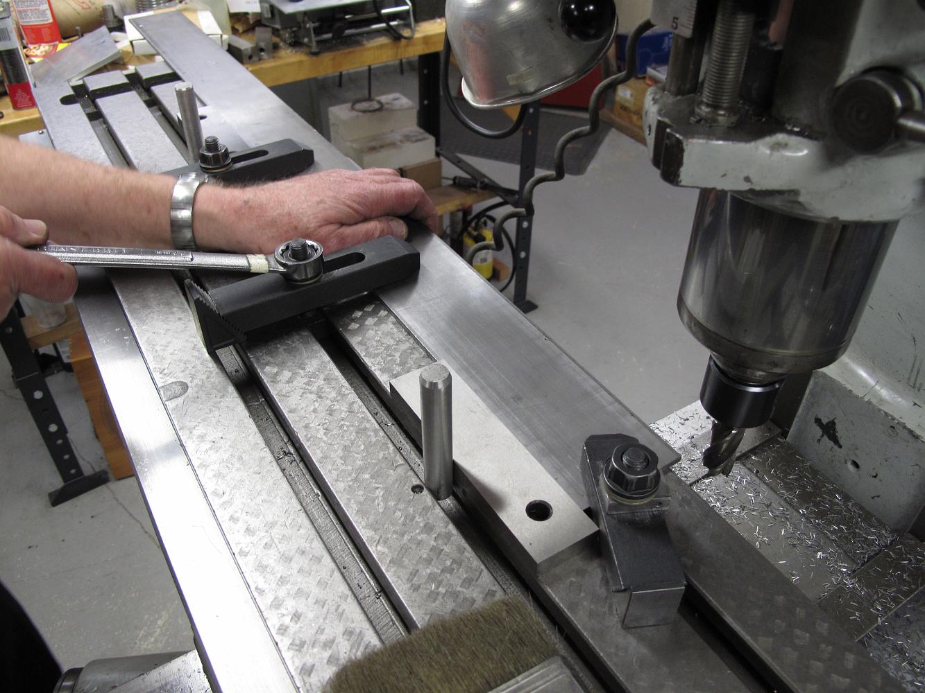
9-Feb-2015 Using table stops (round aluminum dowels vertically in the slots) to position the rear running board, Bill machines a true edge on the stock.
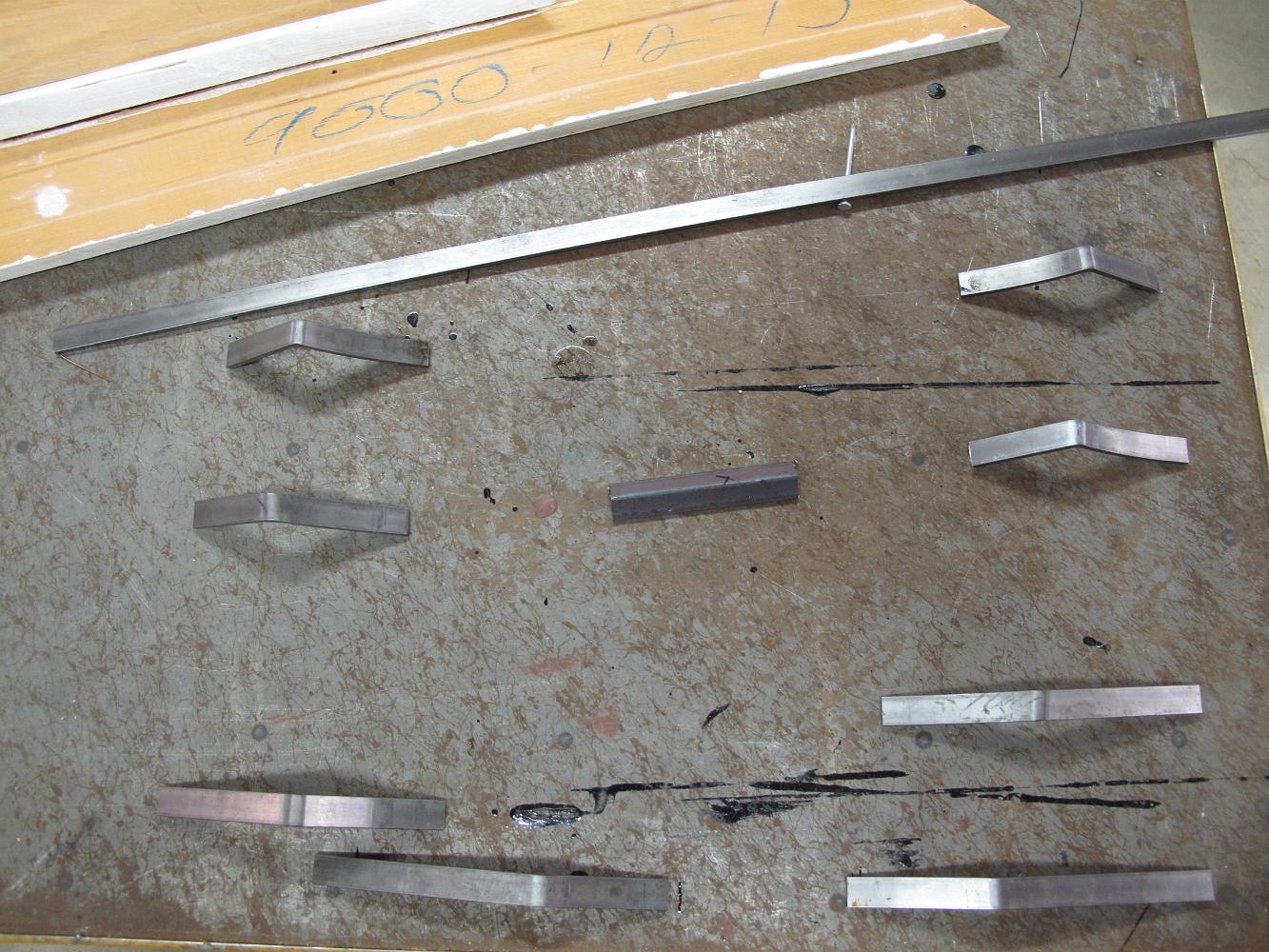
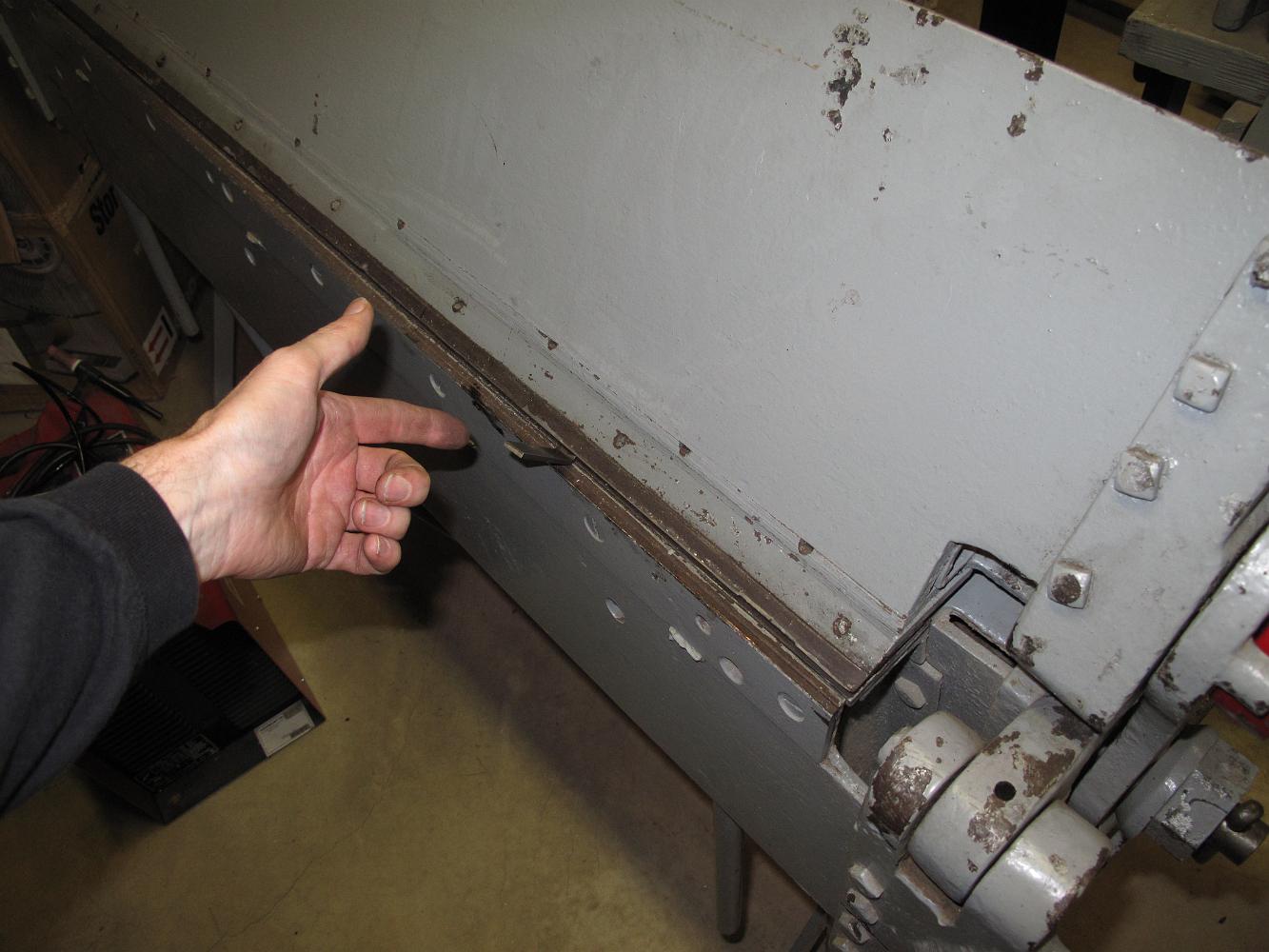
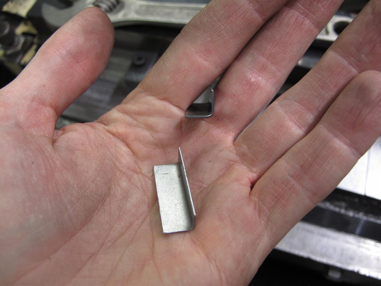
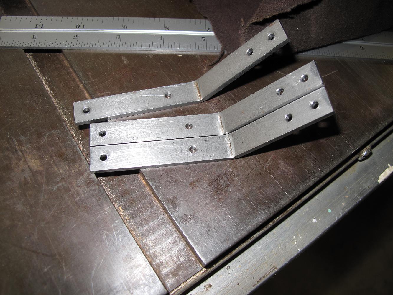
2-Feb-2015 The different brackets bent to support the running boards, with matching curved radius for each course of jacketing. The brackets nearest the bottom…
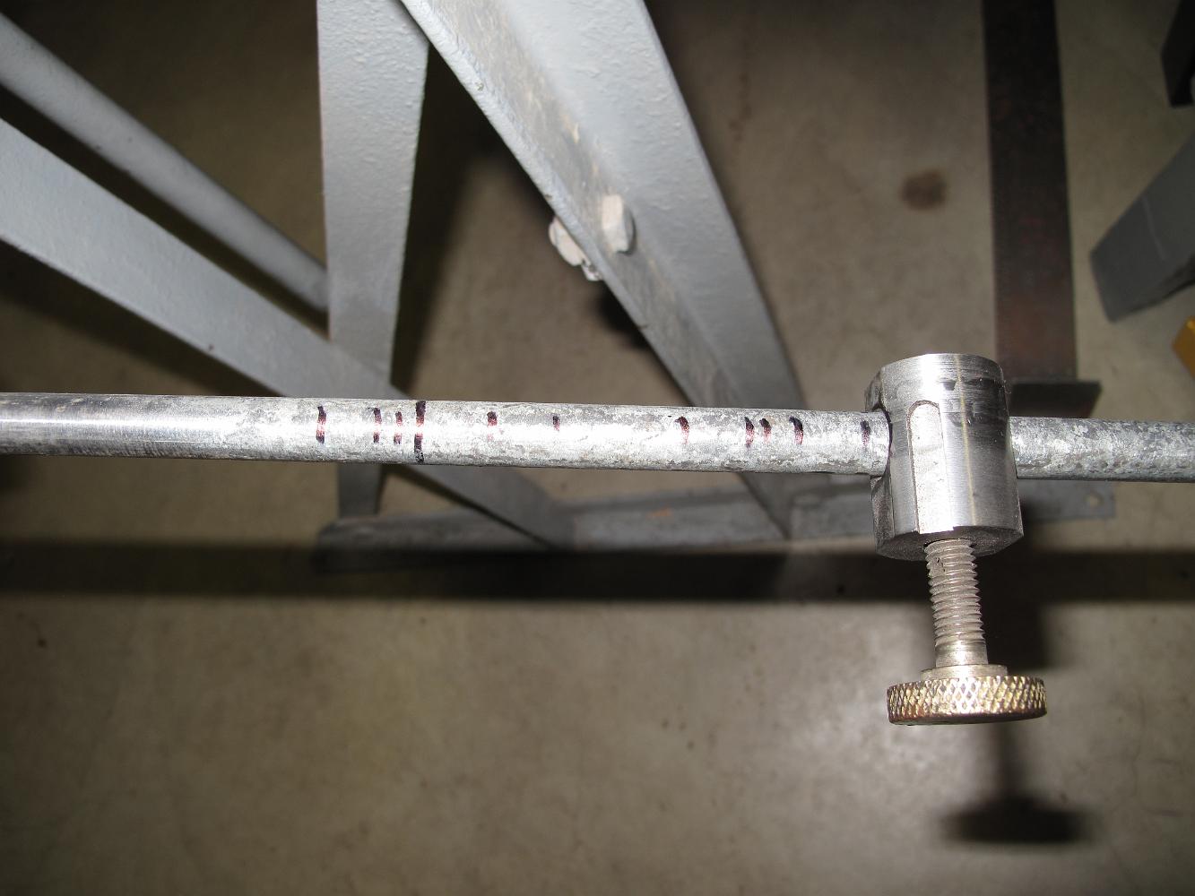
2-Feb-2015 The many marks of trial bends on the bend stop.
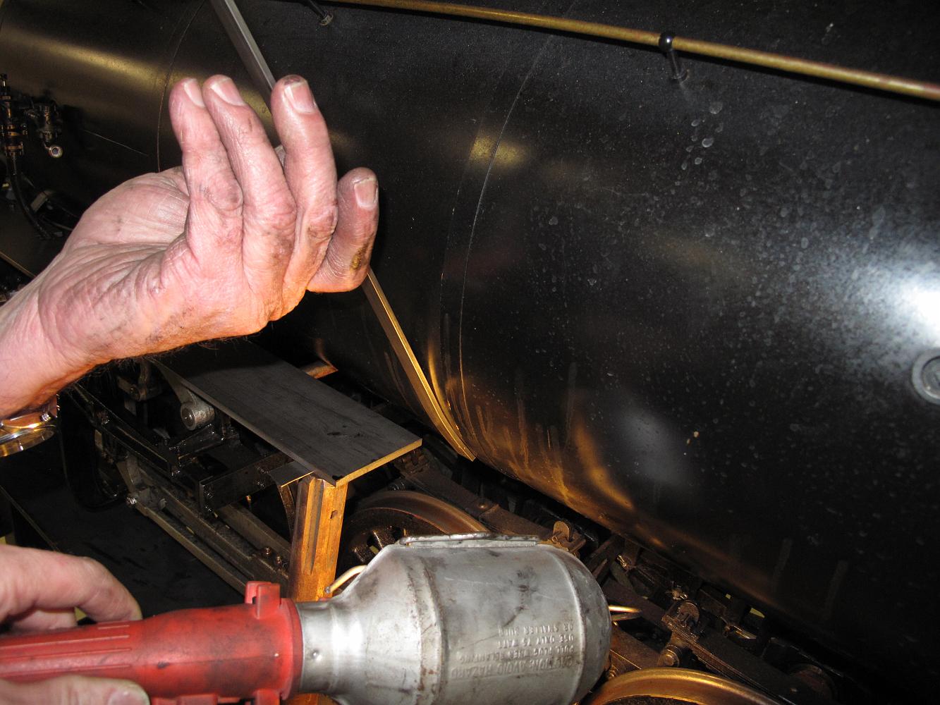
2-Feb-2015 Bending the bracket at an angle for the tapered jacketing course.
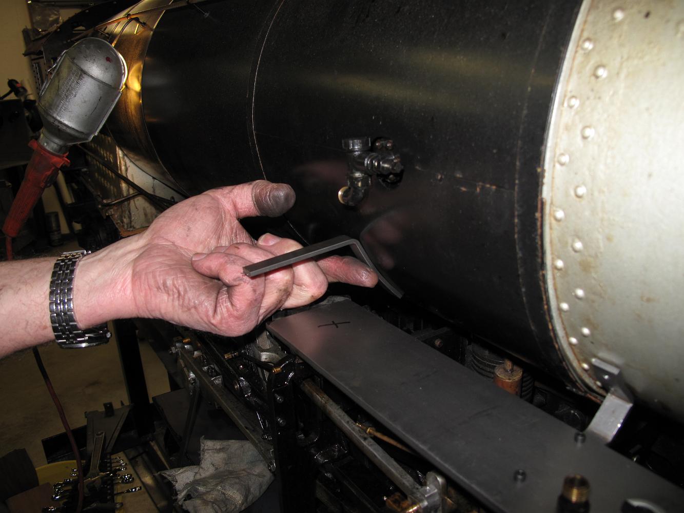
2-Feb-2015 Trying to figure out how to make the bend on the bracket to make it square to the running board. This bracket is on the tapered course of jacketing,…
2-Feb-2015 We start working on the rest of the running board brackets. The running boards on the Frisco 4166 are a bit different than the USRA design, so we…
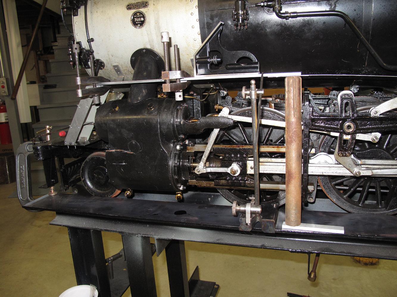
19-Jan-2015 Glamour shot of engine with steps installed.
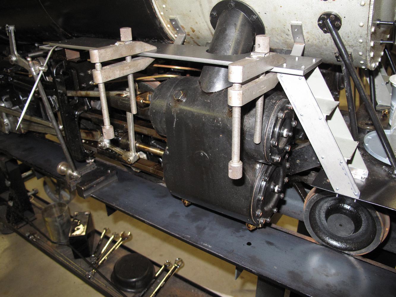
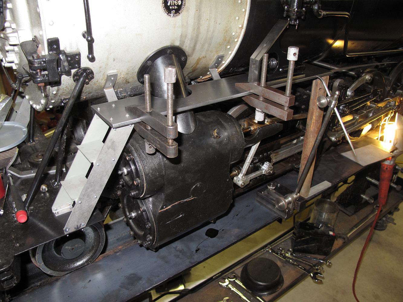
19-Jan-2015 We start working the Engineer's side running board. We will have to do something about the lubricator location, which now interferes with the…
19-Jan-2015 Match drilling the running board bracket holes in the running board, using the pre-existing holes in the brackets. We previously clamped the…
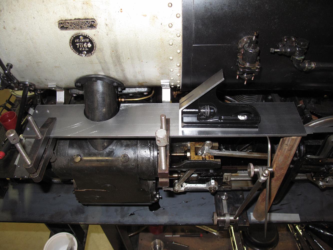
19-Jan-2015 With the running board bolted to the stairs and leveled at the other end, the running board brackets are clamped to the running board to match drill…
19-Jan-2015 We have the stairs installed and the running board leveled, now we can locate where the brackets need to go on the smokebox. Since we did not…
19-Jan-2015 Now that we have assembled stairs, we will know the actual height of the front running board.
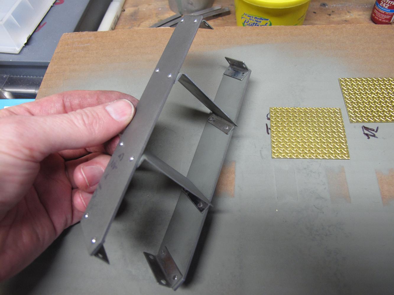
19-Jan-2015 Using 1/16" steel round head rivets, we easily rivet the brackets and support treads to one side. Riveting the other side was harder because I do…
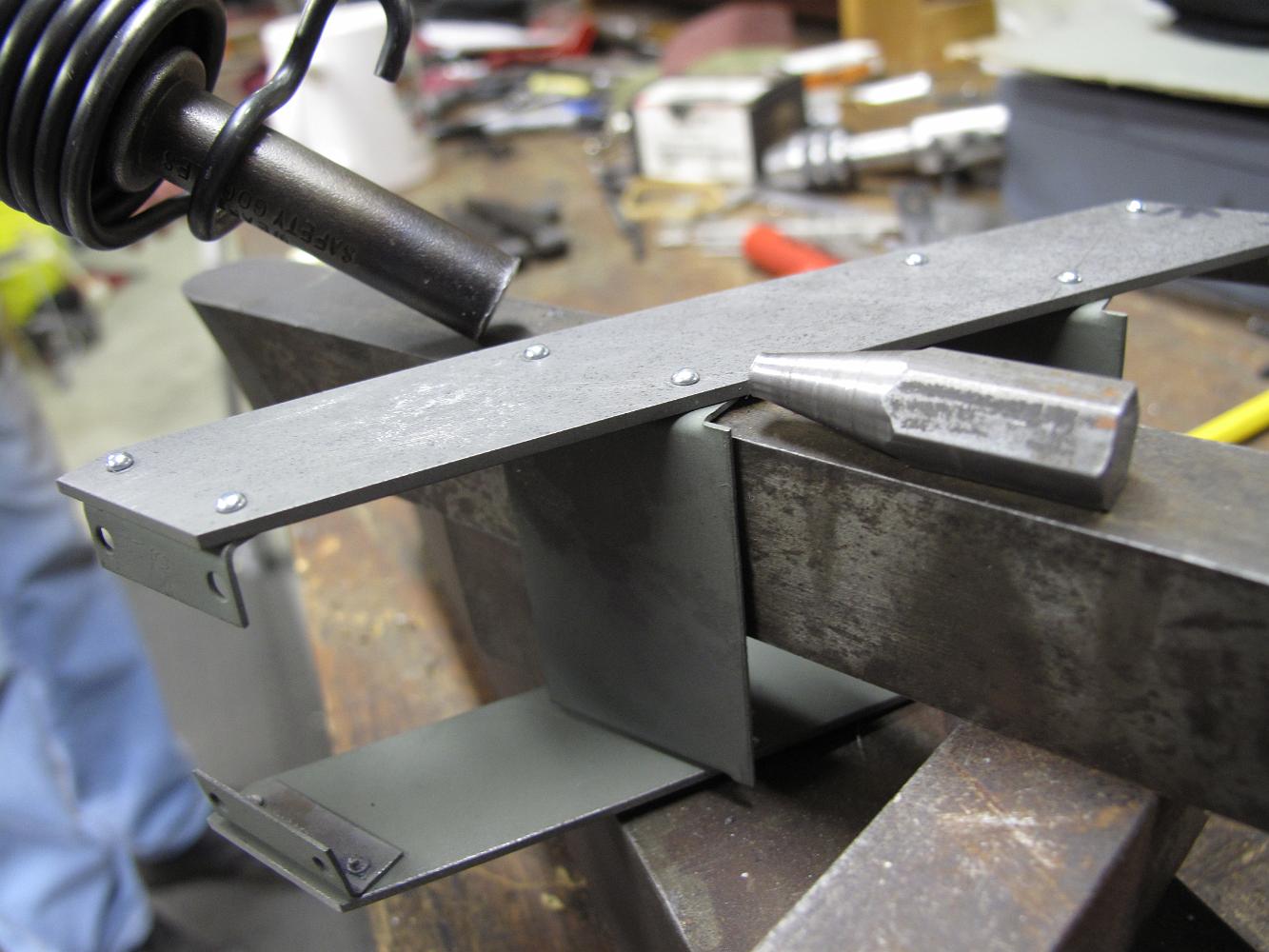
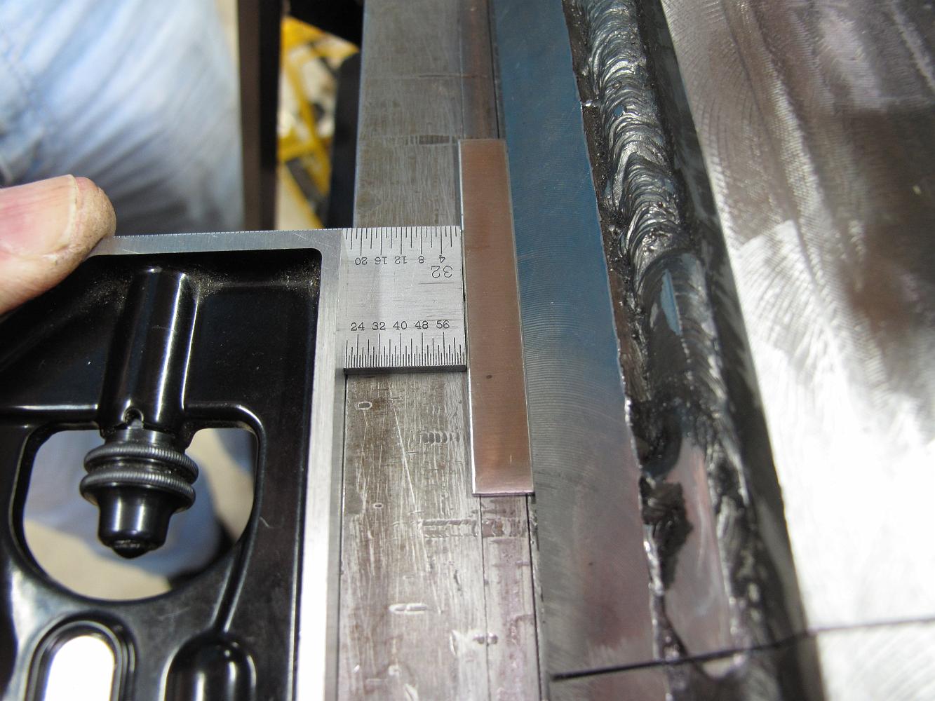
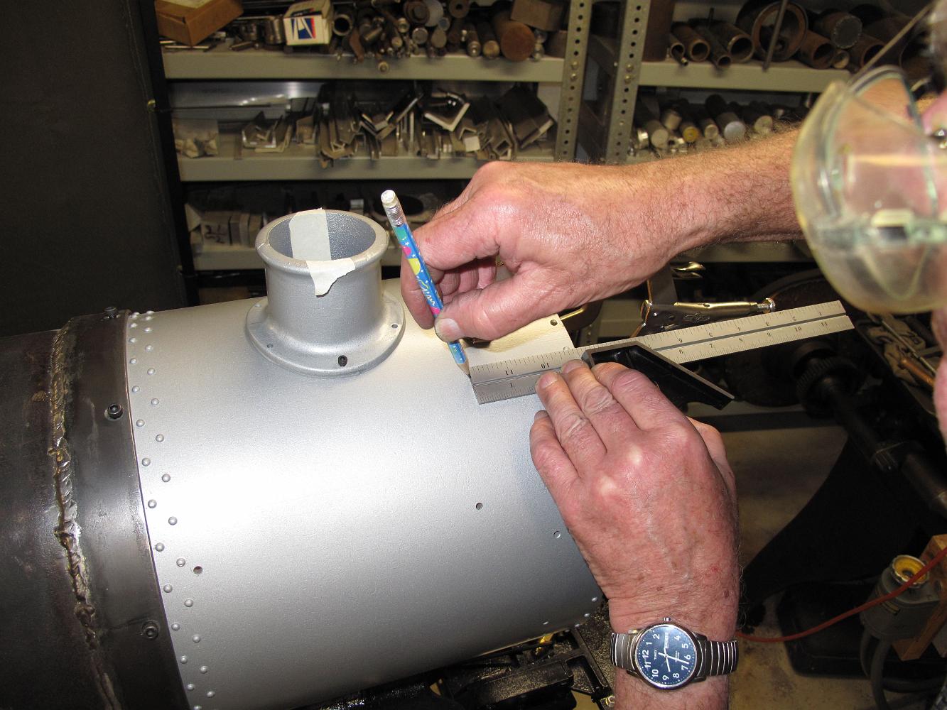
12-Jan-2015 We fuss with how much should stick out before bending to make the stair brackets end up the correct width. We use the combination rule as a depth…
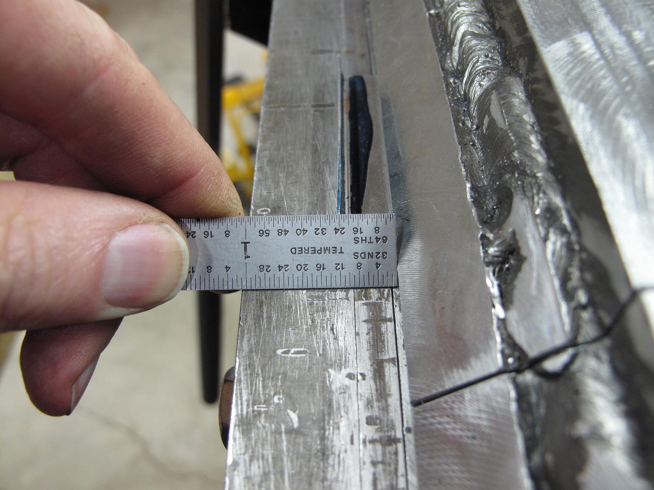
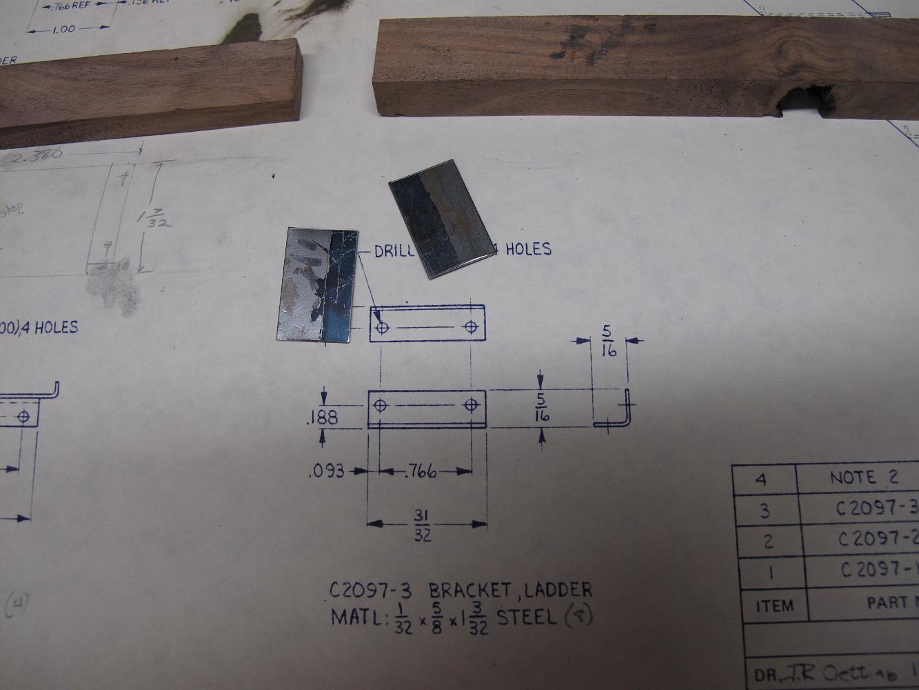
12-Jan-2015 To bend the ladder brackets, the finger brake fingers are set back 1/32" inch from the bend point.
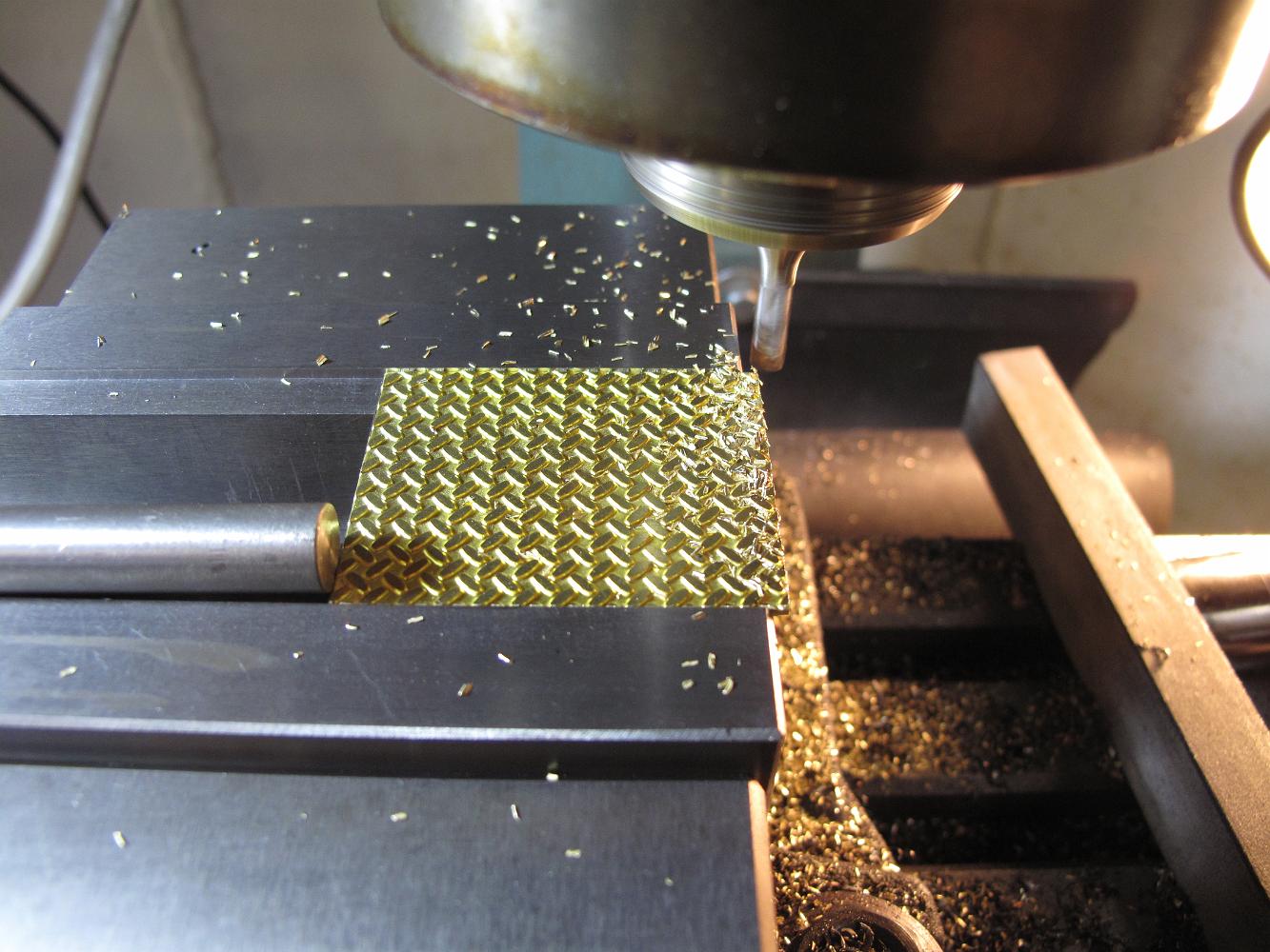
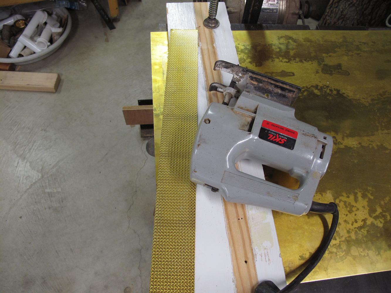
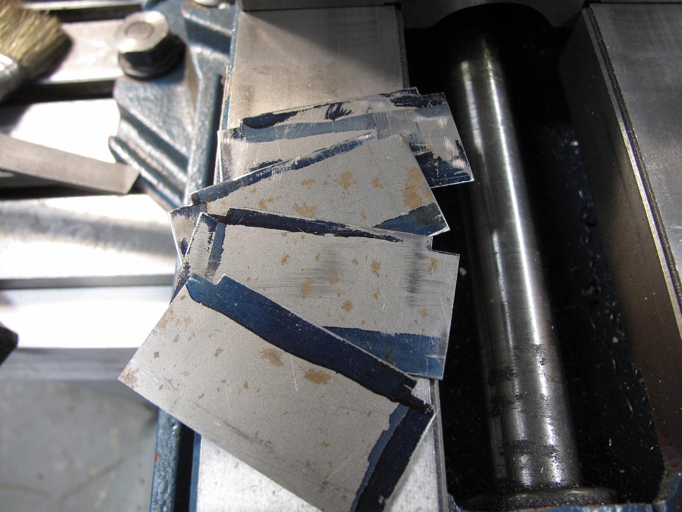
5-Jan-2015 While Bill is machining the stair sides, I cut a piece of stamped model diamond plate off for the stair treads. I think I bought this brass sheet…
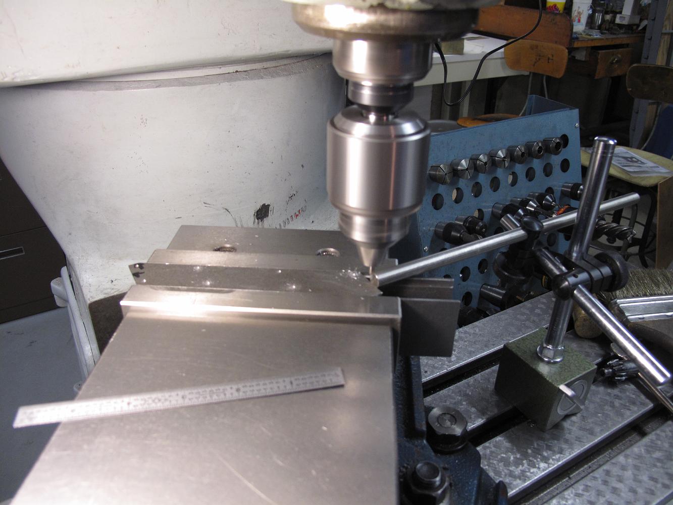
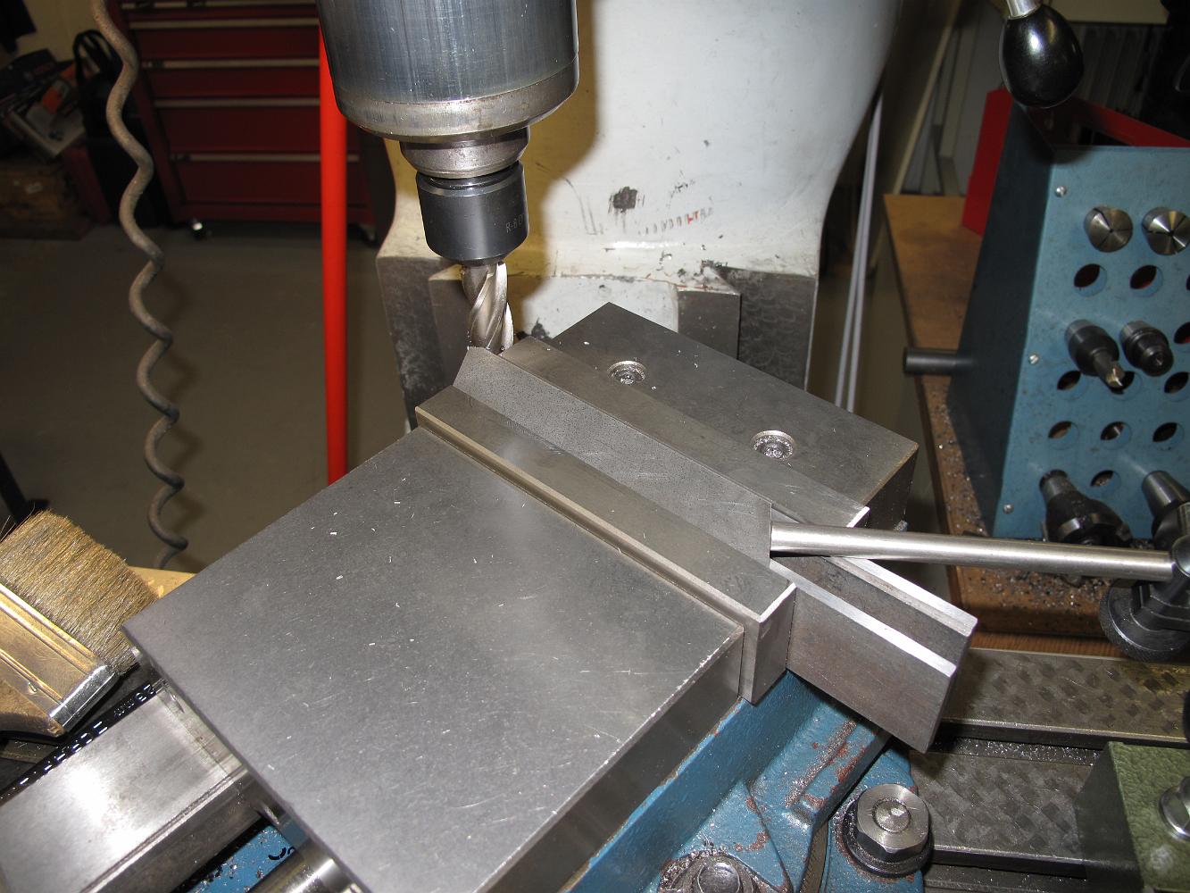
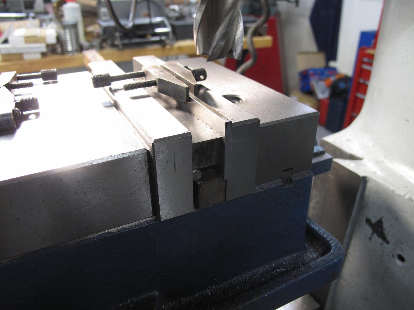
5-Jan-2015 With the stair side in the vise, the vise is swiveled around until the stair end (bottom or top) reads zero when measuring the Y-axis (front to…
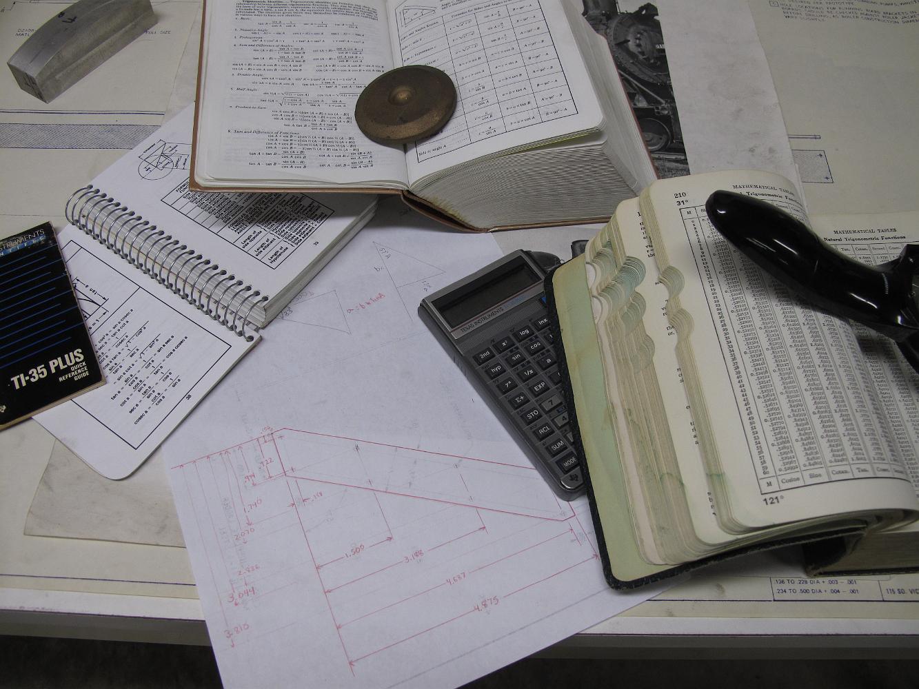
5-Jan-2015 I spend an hour or so learning how to calculate cotangents so I can translate the drawing dimensions to be from a 0,0 origin point instead of from a…
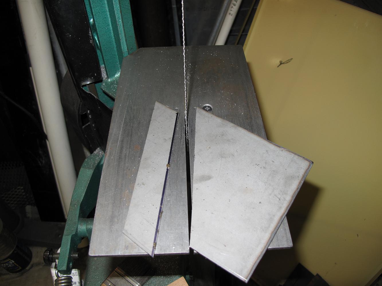
3-Jan-2015 While Bill works on the running boards, I set up the band saw in vertical mode and saw cut 0.101 steel sheets for the pilot steps.
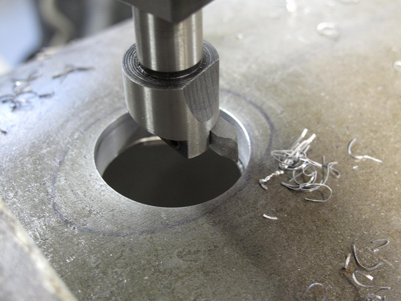
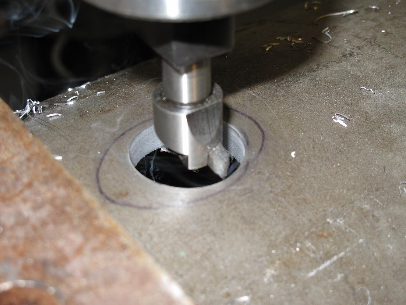
3-Jan-2015 Setup to machine the running boards; cutout for the steam supply shroud. Start with a small, hole, working our way up the finished size.
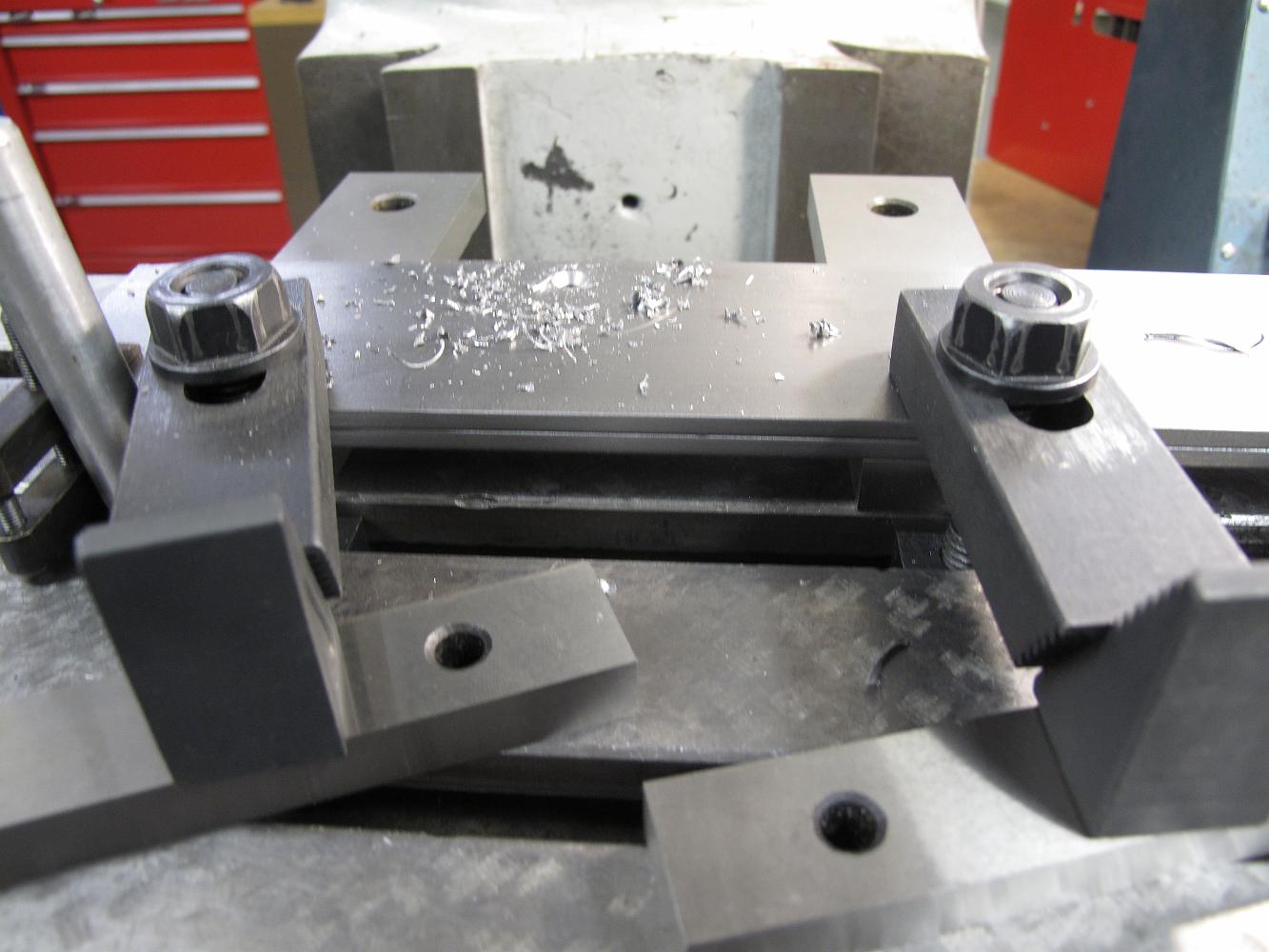
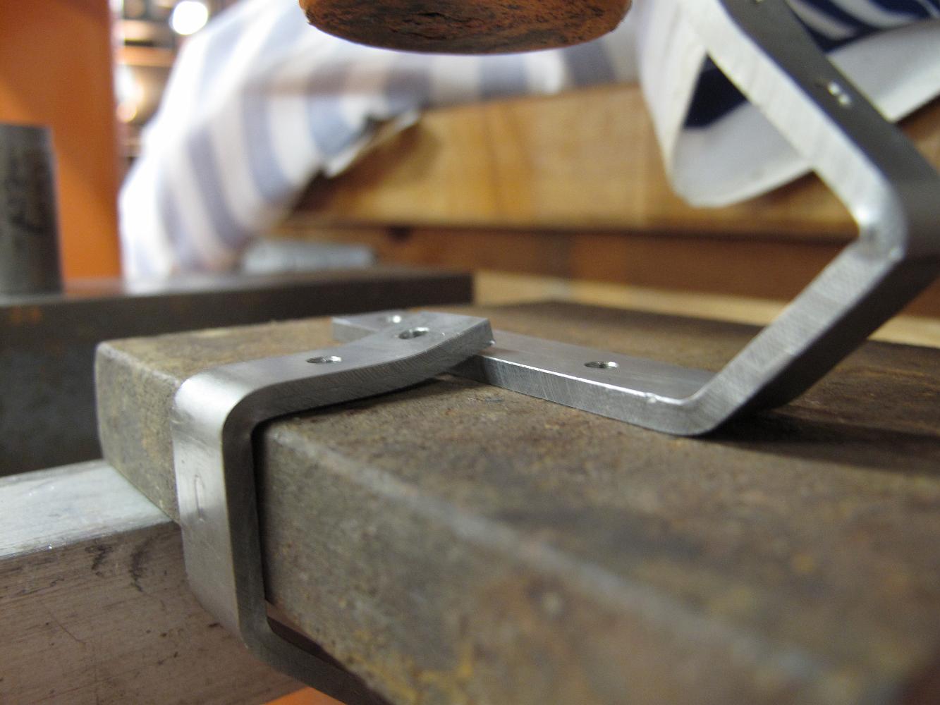
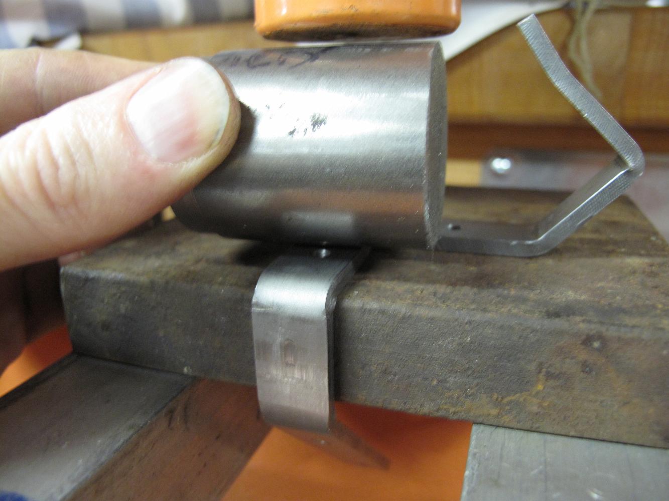
3-Jan-2015 The bracket which is wrapped around the rusty piece of steel is the one being bent by the shop press and a piece of round stock. The other bracket on…
3-Jan-2015 Our solution to putting a radius on the front brackets: use the shop press and a piece of metal to bend the bracket.
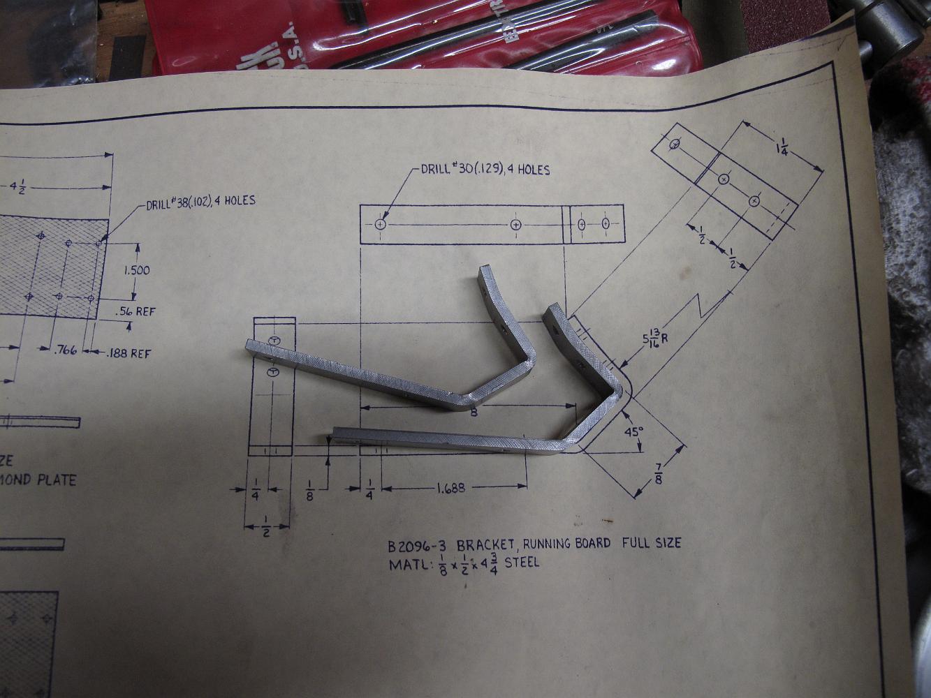
3-Jan-2015 We started the front running board brackets several years ago, but were stumped on how to put the radius on portion which bolts to the…
3-Jan-2015 We begin working on the running boards; front ones first. Start by squaring up the stock, cold-rolled 1018.
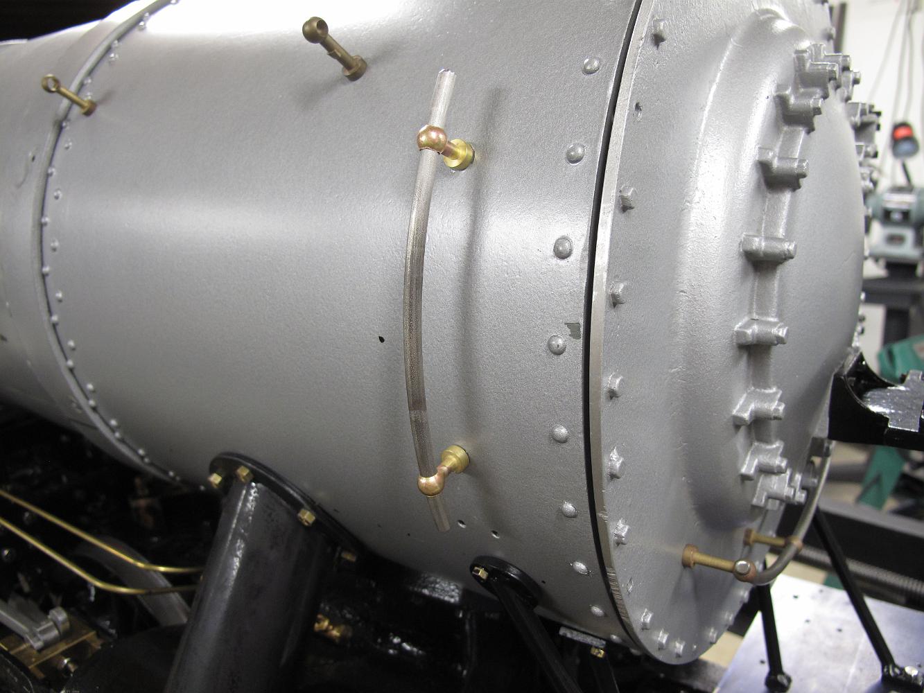
2-July-2012 After looking at pictures of Frisco 4150, I decided that the vertical handrail stanchions were too tall--the prototype has the handrail much closer…
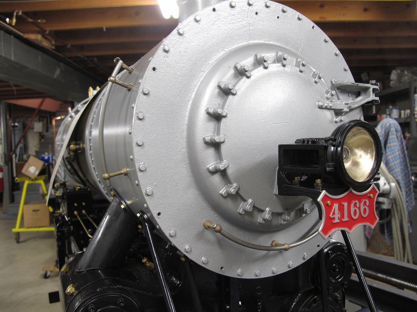
23-June-2012 The front end gains some character! My new Frisco road number plate from Robert Dustin has been mounted, along with the headlight and handrails!
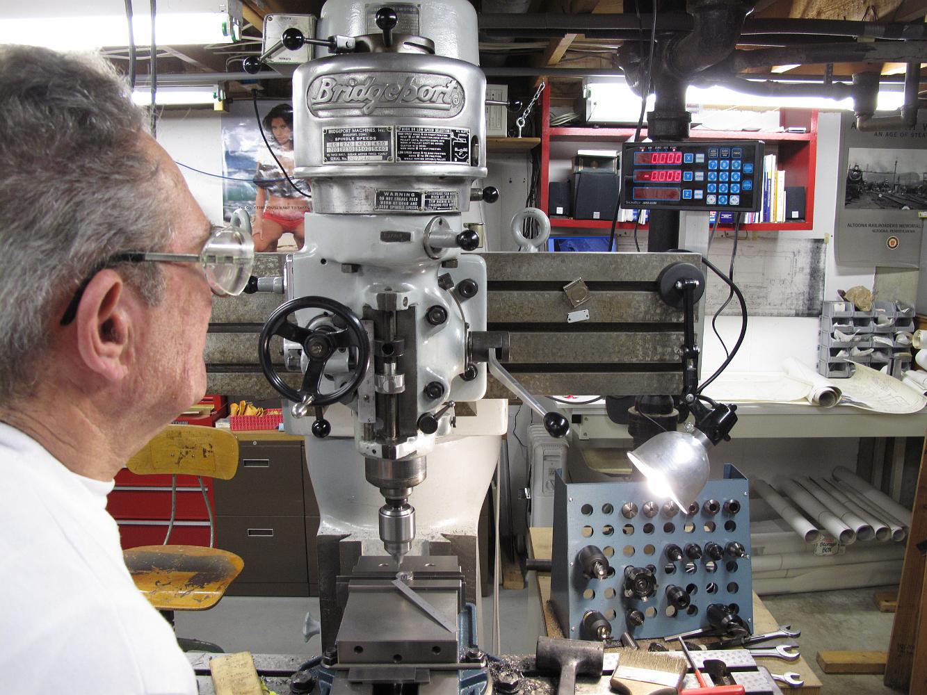
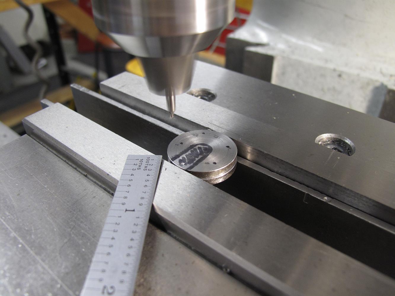
23-June-2012 Machining the bottom of the headlight casting flat, then drilling mounting hole through feet. Held upside down in the vise with the, I used the…
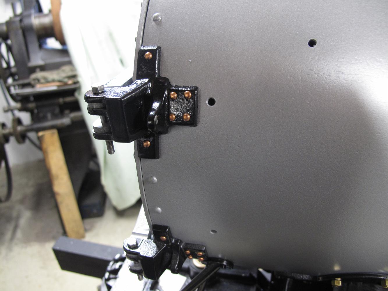
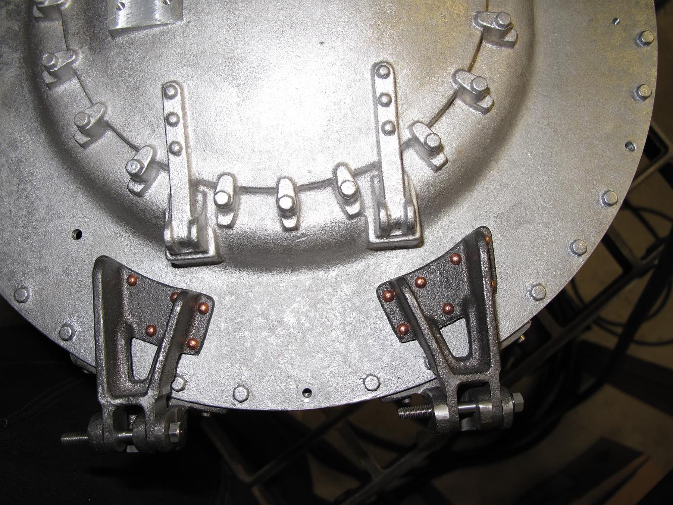
16-Jan-12 The front end is getting closer to being finished! Hinges riveted on, braces complete and shroud fitted.
16-Jan-12 an amusement for me: I have been looking for these rivets to rivet the hinges to the smokebox for several months now. I have been scouring boxes on…
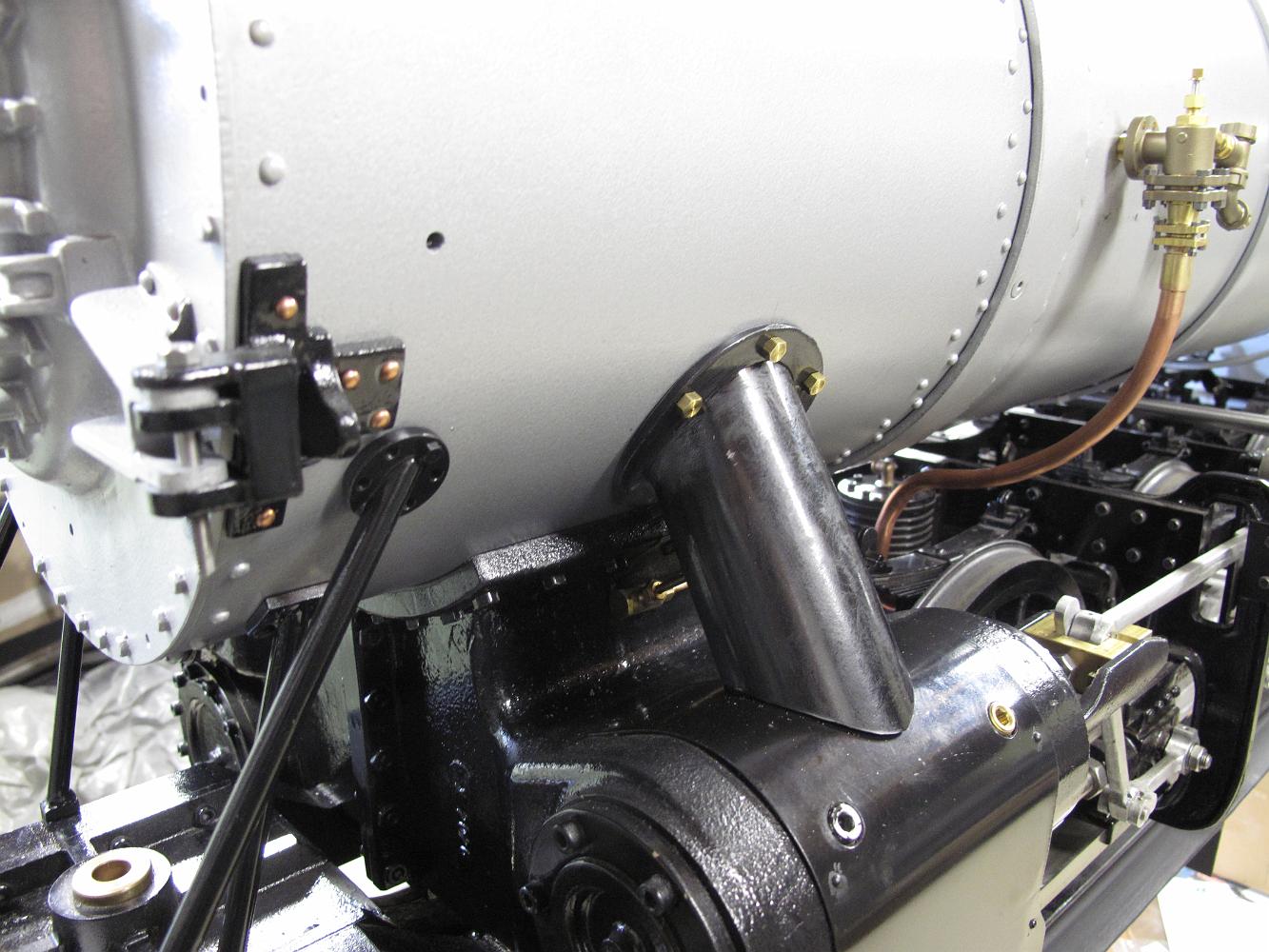
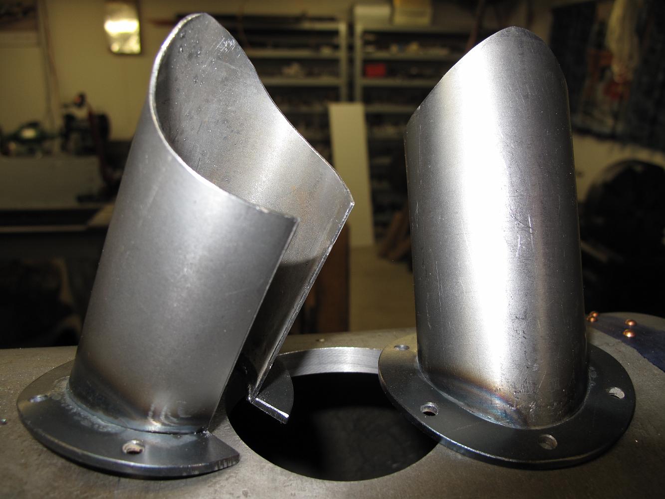
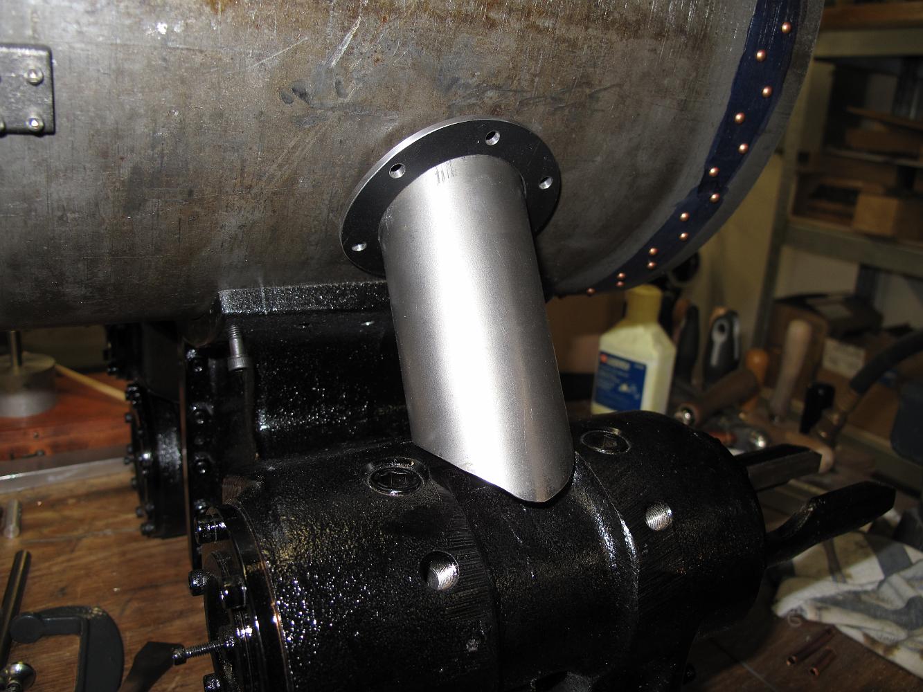
7-Jan-12 I pick up the main steam supply shrouds which have sat for many months and fit them for final assembly. The bottom profile needed to be adjusted to fit…
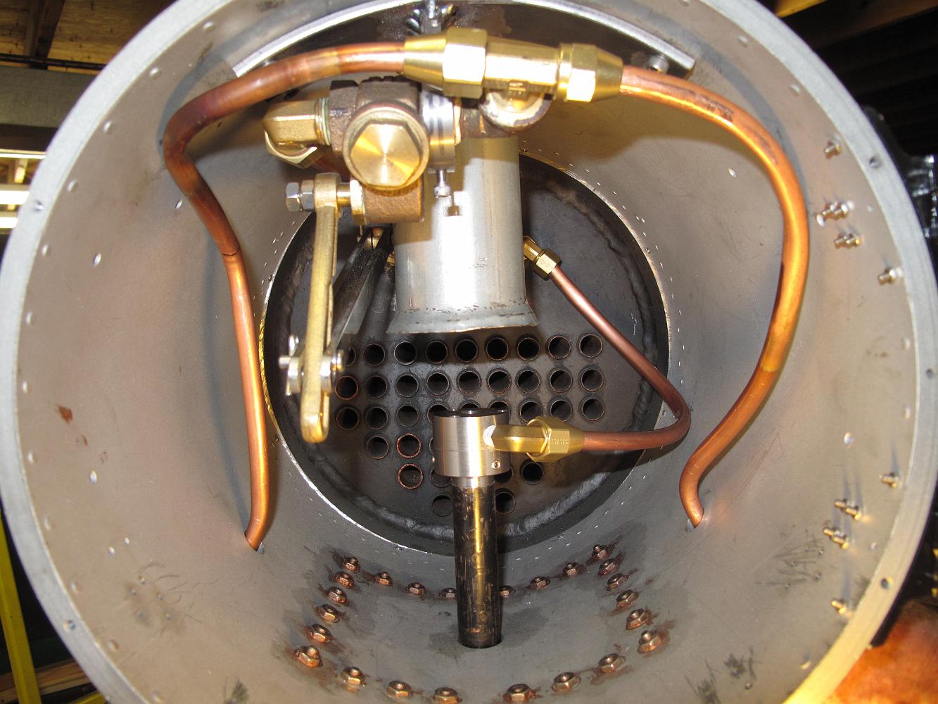
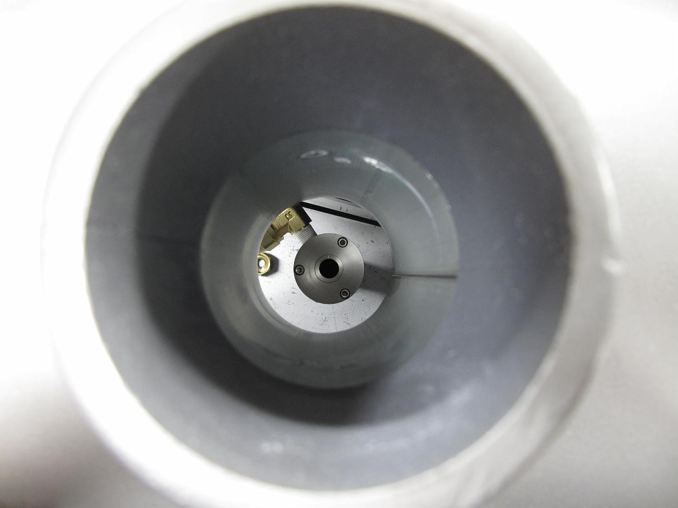
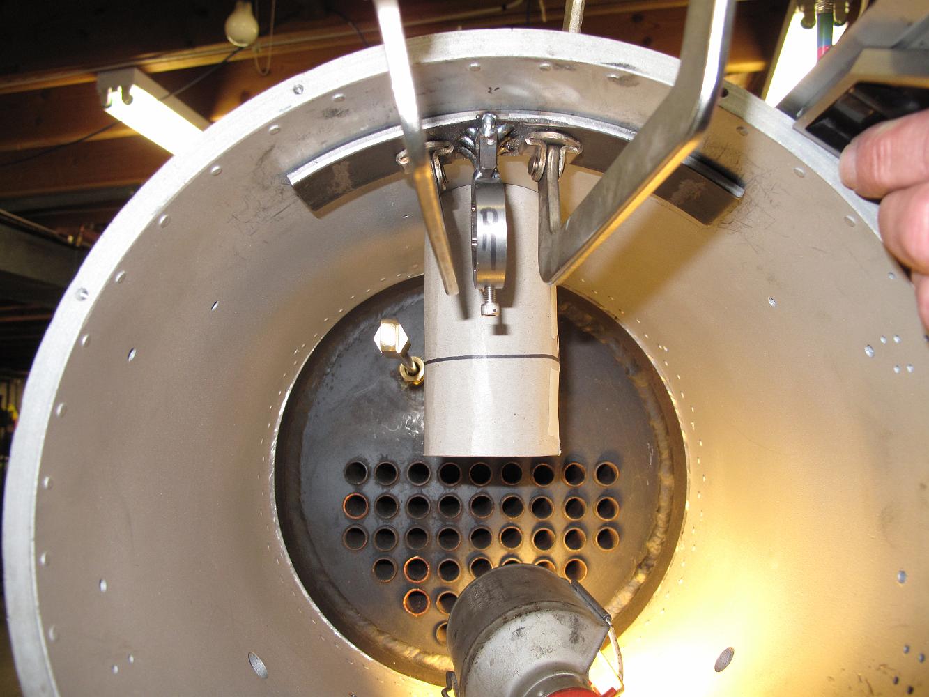
15-June-2011 Alignment check with the stack, petticoat and blast nozzle/blower ring assembly. Looks Good! An air test with the blower also felt good, moving a…
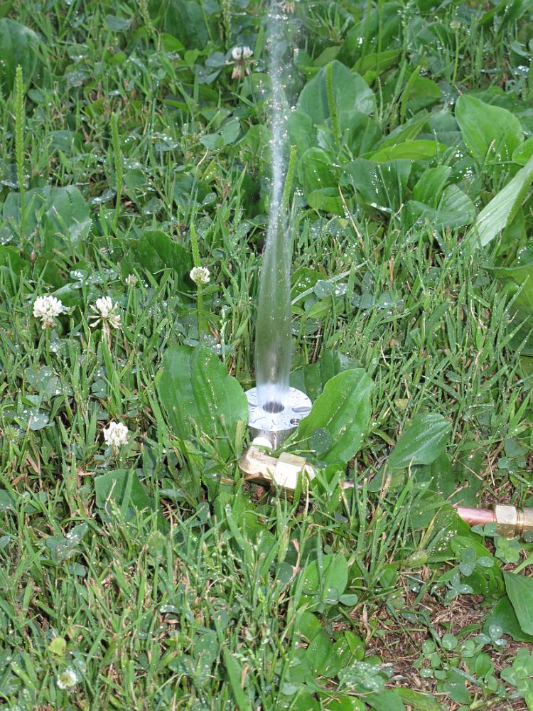
15-June-2011 Water spray test outside after polishing the inside and outside blower ring openings with 600 grit sandpaper. It has a nice even ring of water with…
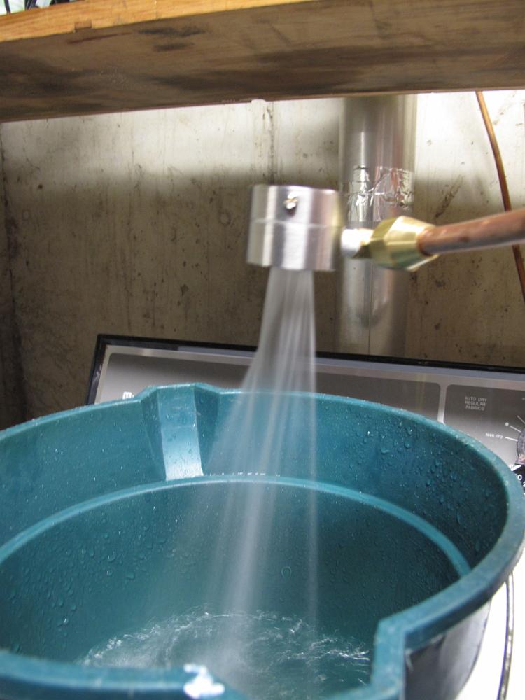
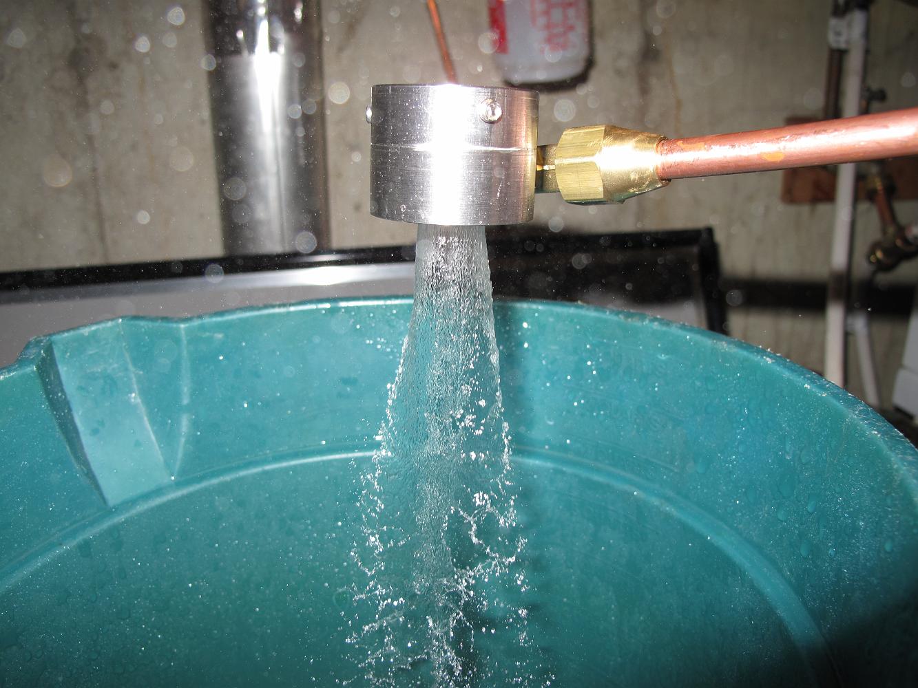
15-June-2011 Water spray test at high pressure showed some streams off at an angle, and a 'dead' spot right where the water enters the assembly.
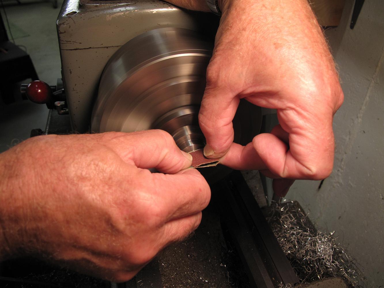
15-June-2011 Using 400 grit, then 600 grit sandpaper to put a polish on the blower ring body after water tests revealed an uneven distribution. Close…
8-June-2011 Drilling and counterboring holes in the blast nozzle ring. It is sitting on a piece of sacrificial aluminum since the holes must go through the…
With both the top and bottom of the blast nozzle finished in the lathe, we bolt it down to the table to drill some holes.
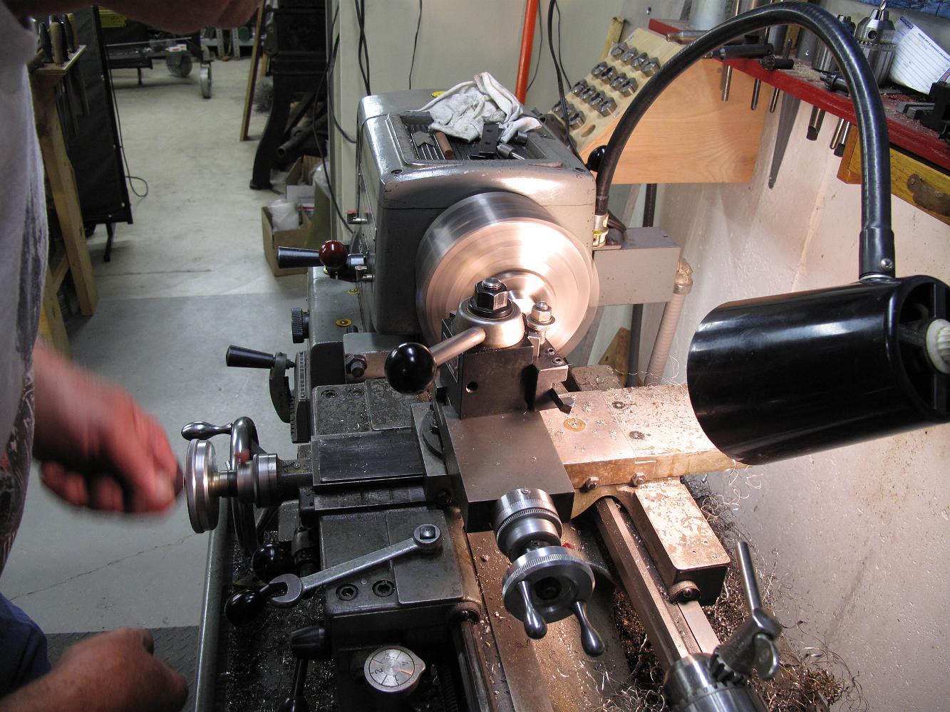
With the cross-compound set over 90 degrees square to the lathe axis, he is able to take accurate amounts off the end of the part for the final thickness.
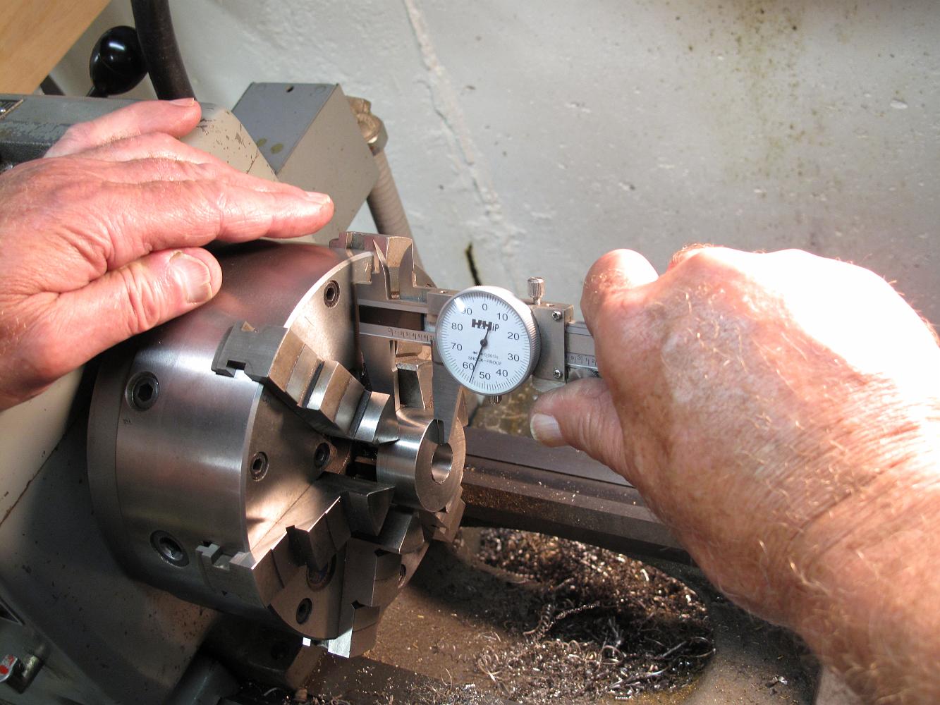
A quick check with the dial calipers for the current thickness. We'd use a micrometer if we could get on between the part and the chuck.
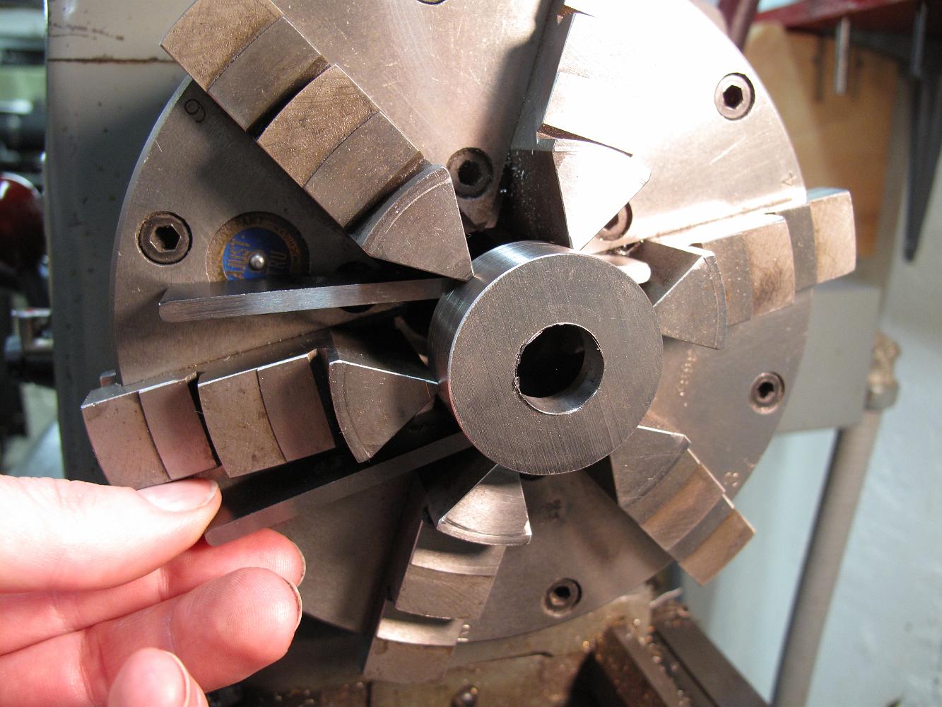
After drilling, the part is turned around and chucked against parallels temporarily put in the chuck. This allows us to measure the thickness of the part…
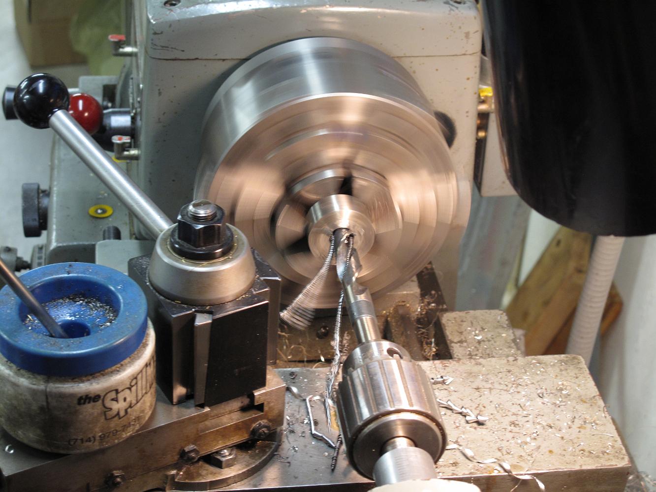
This is a two part assembly, the lower one is being turned now. The upper one will have the blower ring on it.
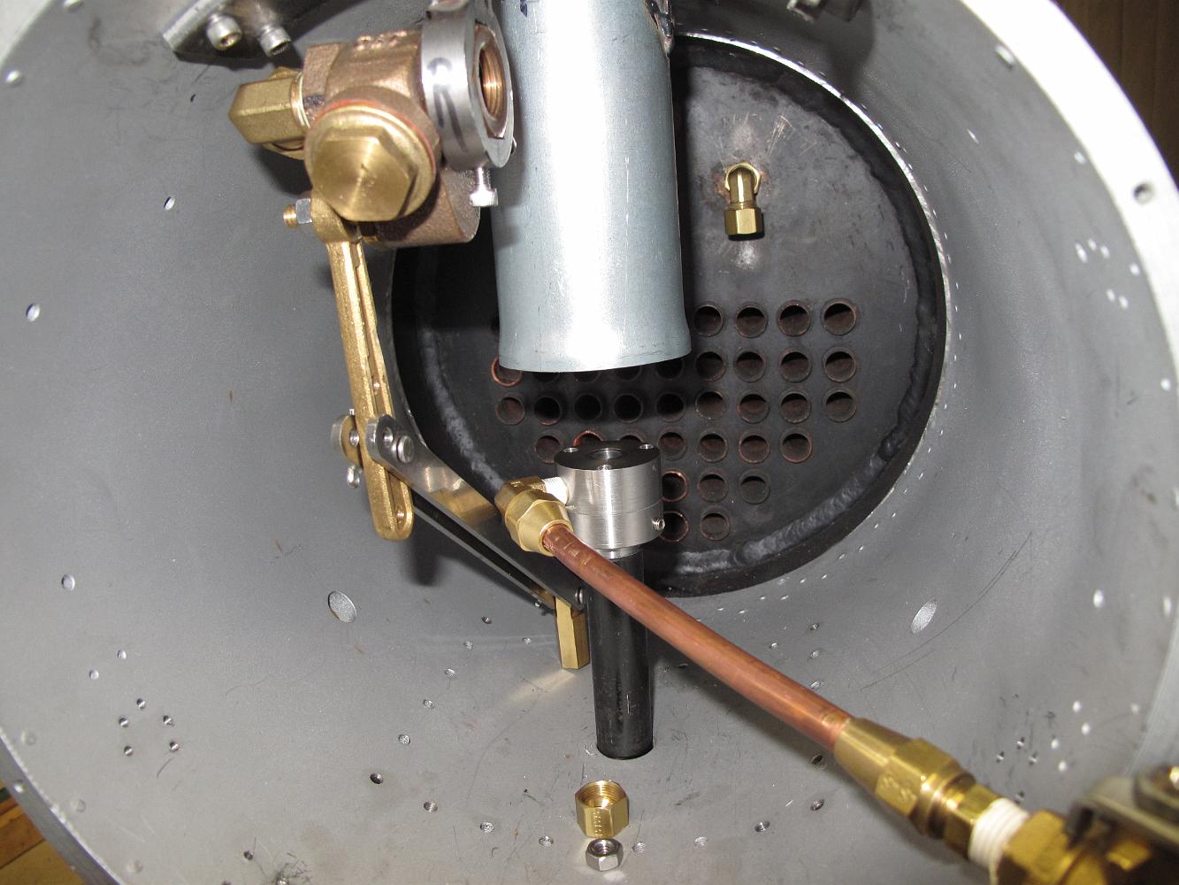
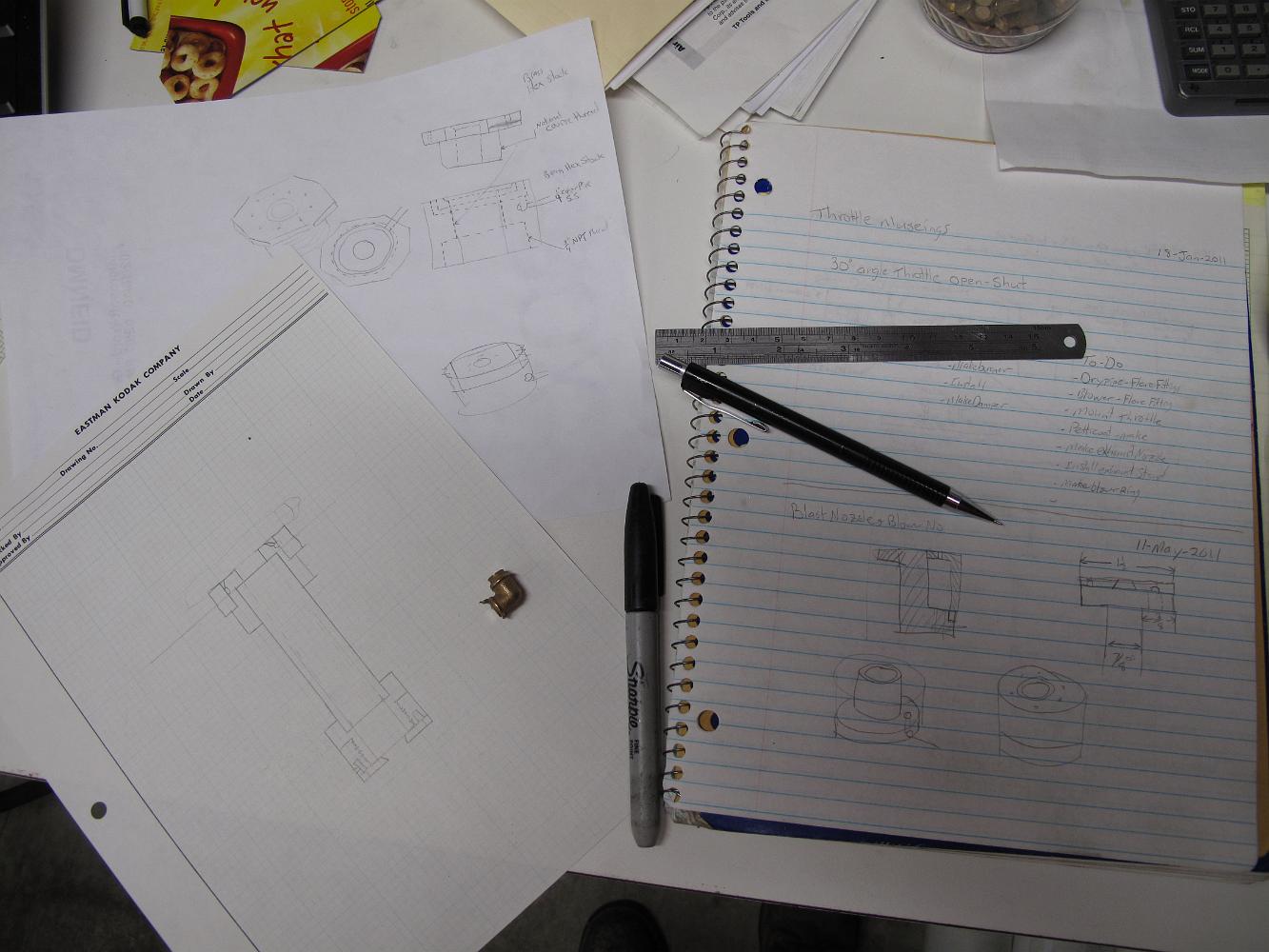
12-May-2011 After the pilot braces were installed, the rest of tonights shop work was devising a blast nozzle/blower combination. There is no doubt the pipe cap…
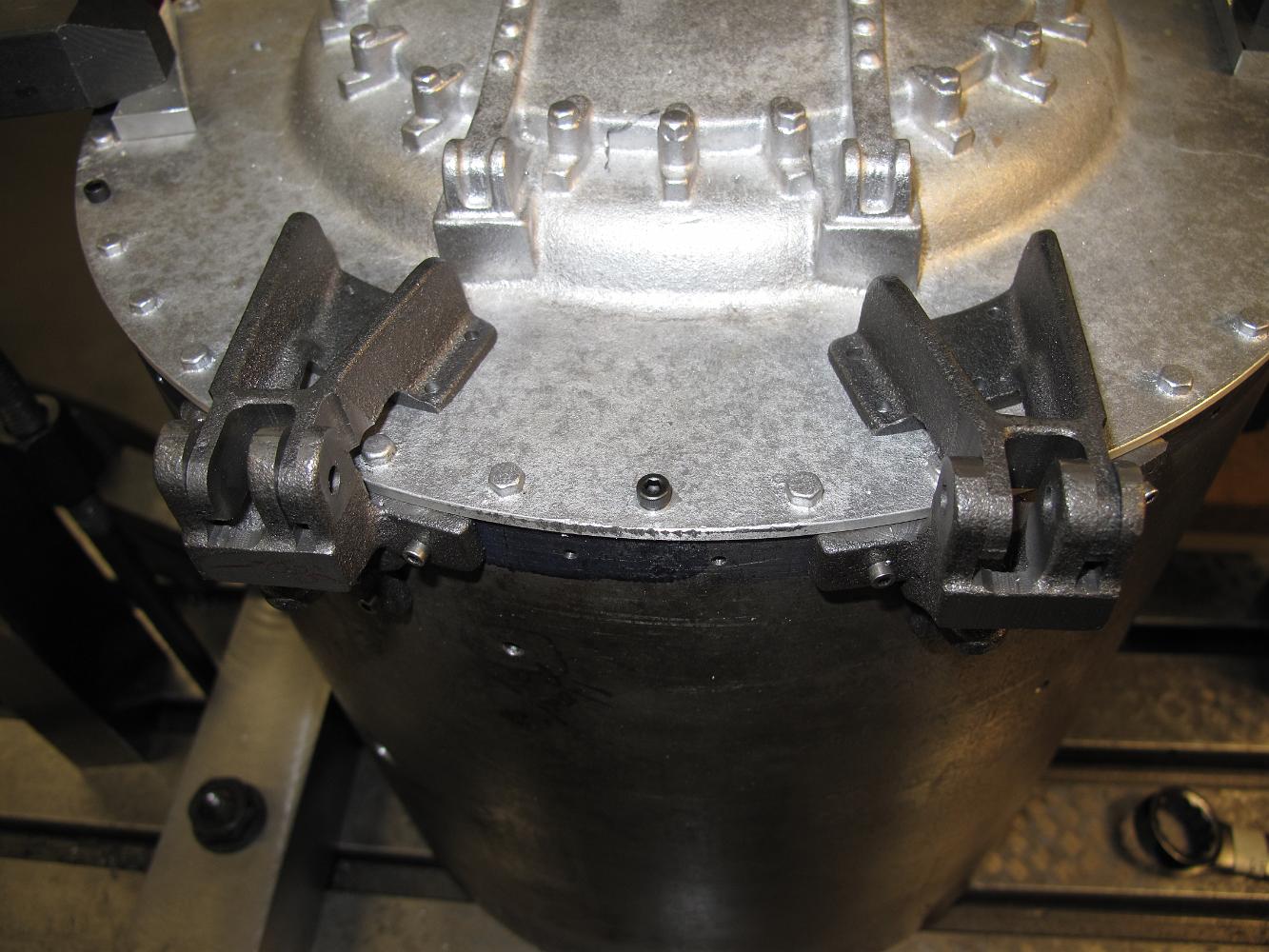
12-May-2011 Ten holes drilled & tapped later, all four pilot braces are installed. This is not their final installation, I need to take them down and finish…
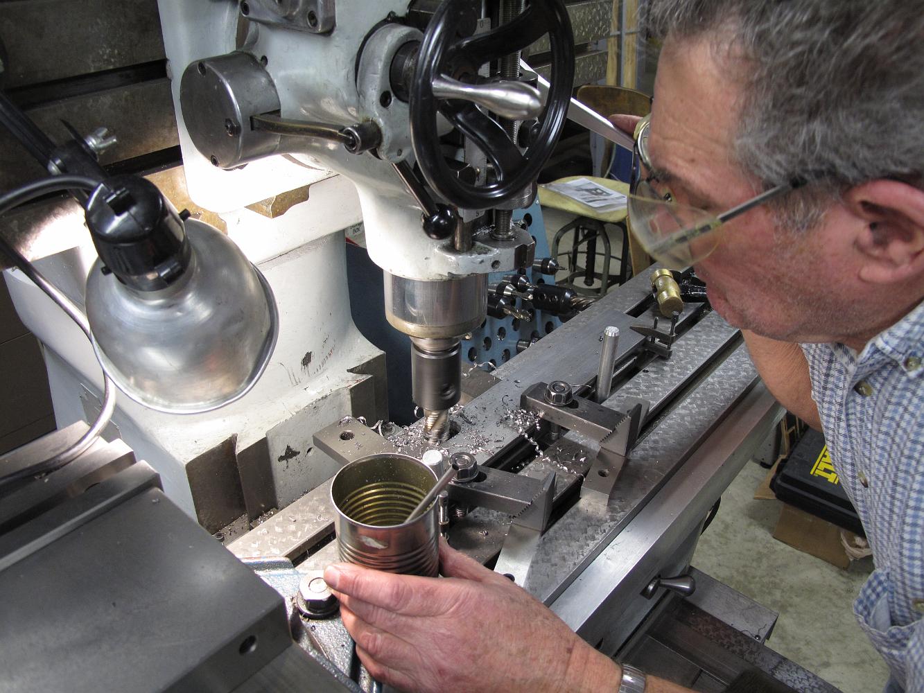
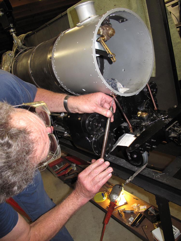
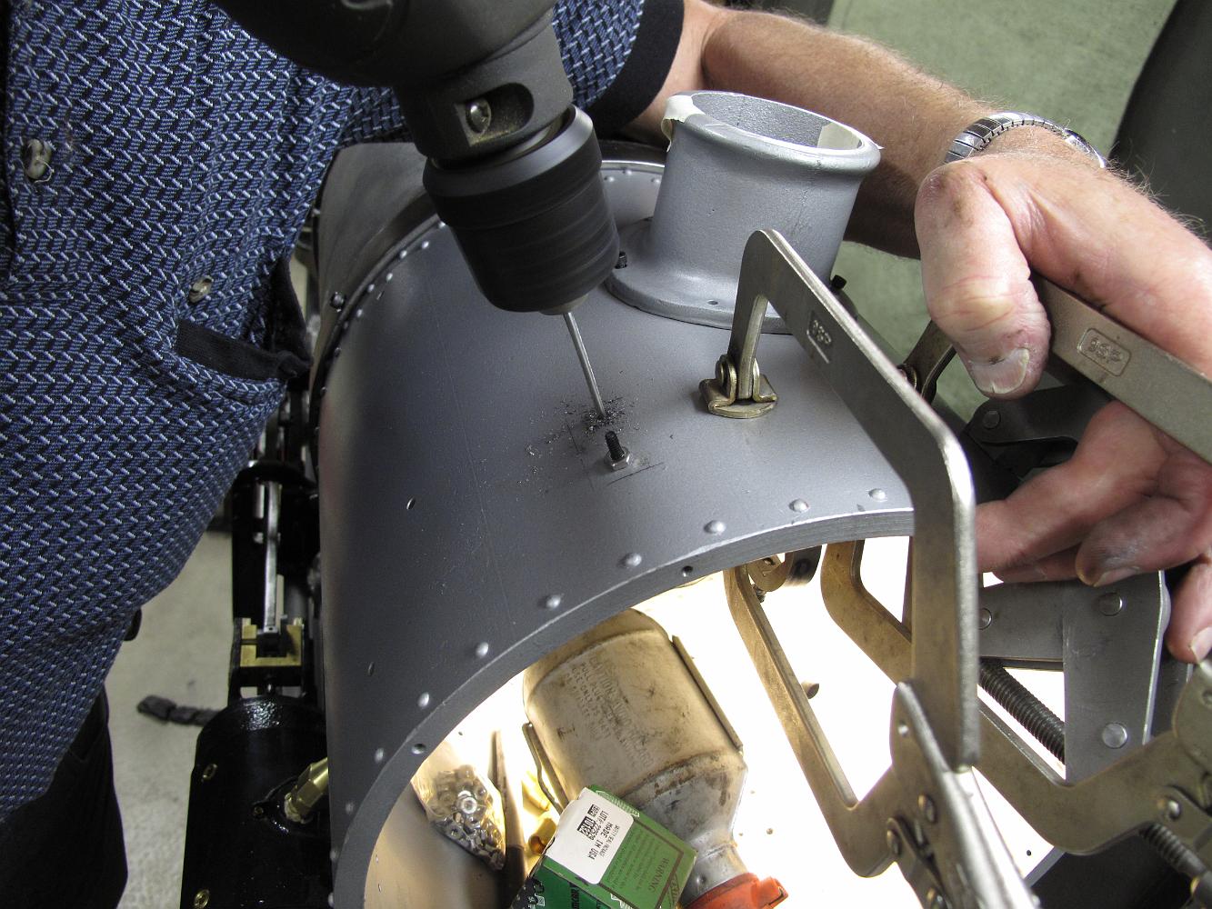
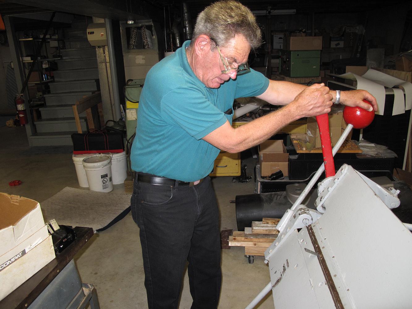
2-May-2011 Tapping the smokebox for the two custom Frisco pilot support braces. Doing this by hand is a real pain! You are holding the drill at a awkward angle,…
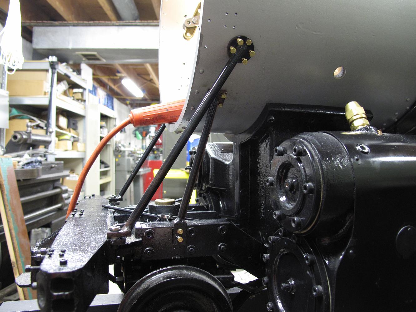
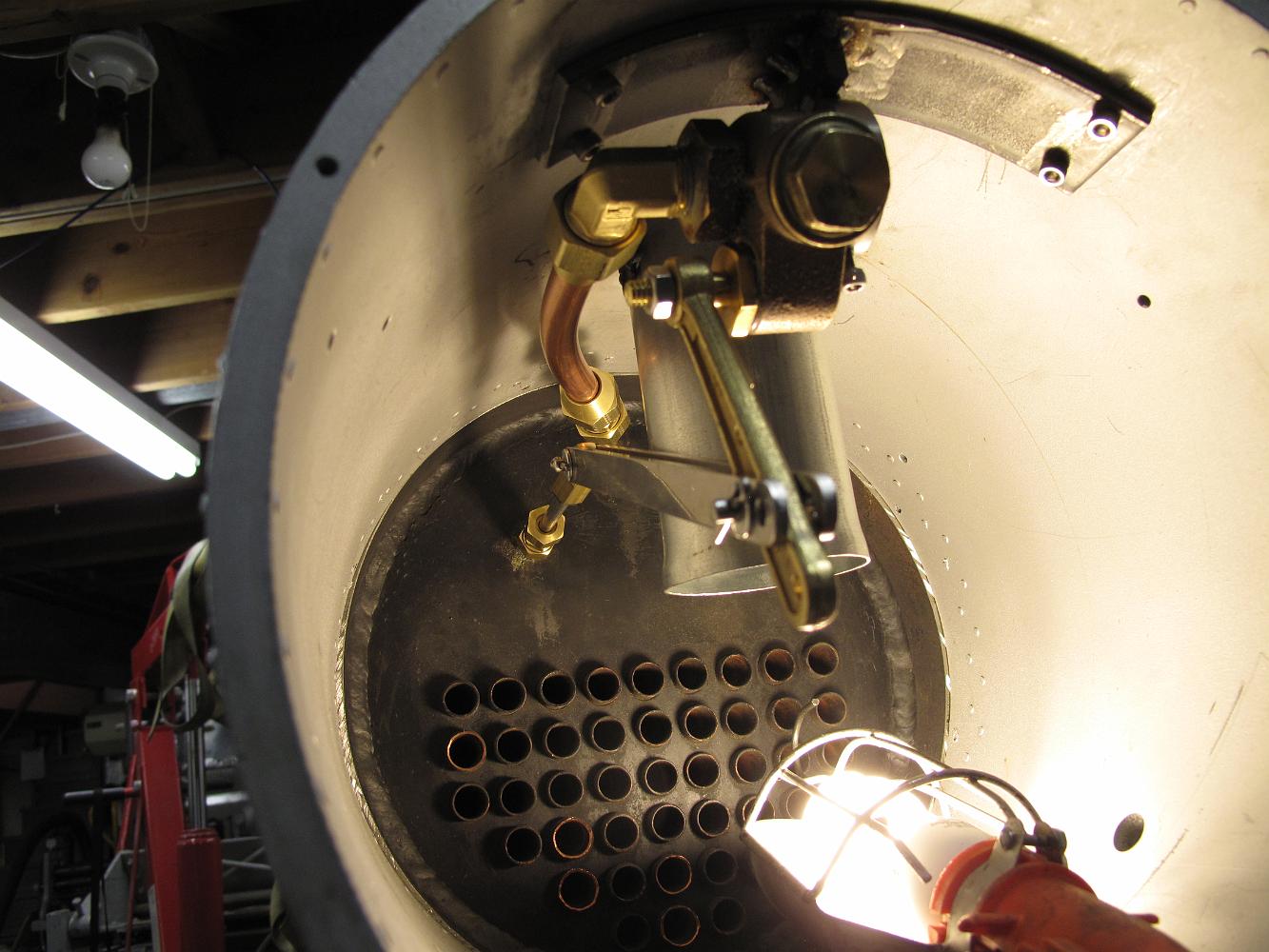
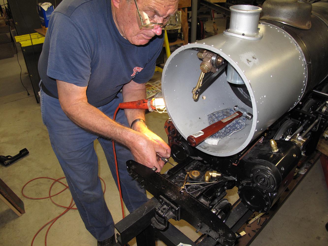
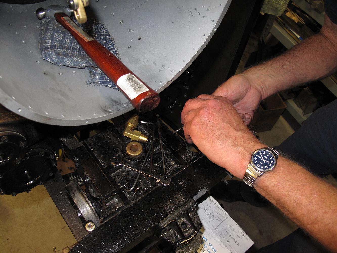
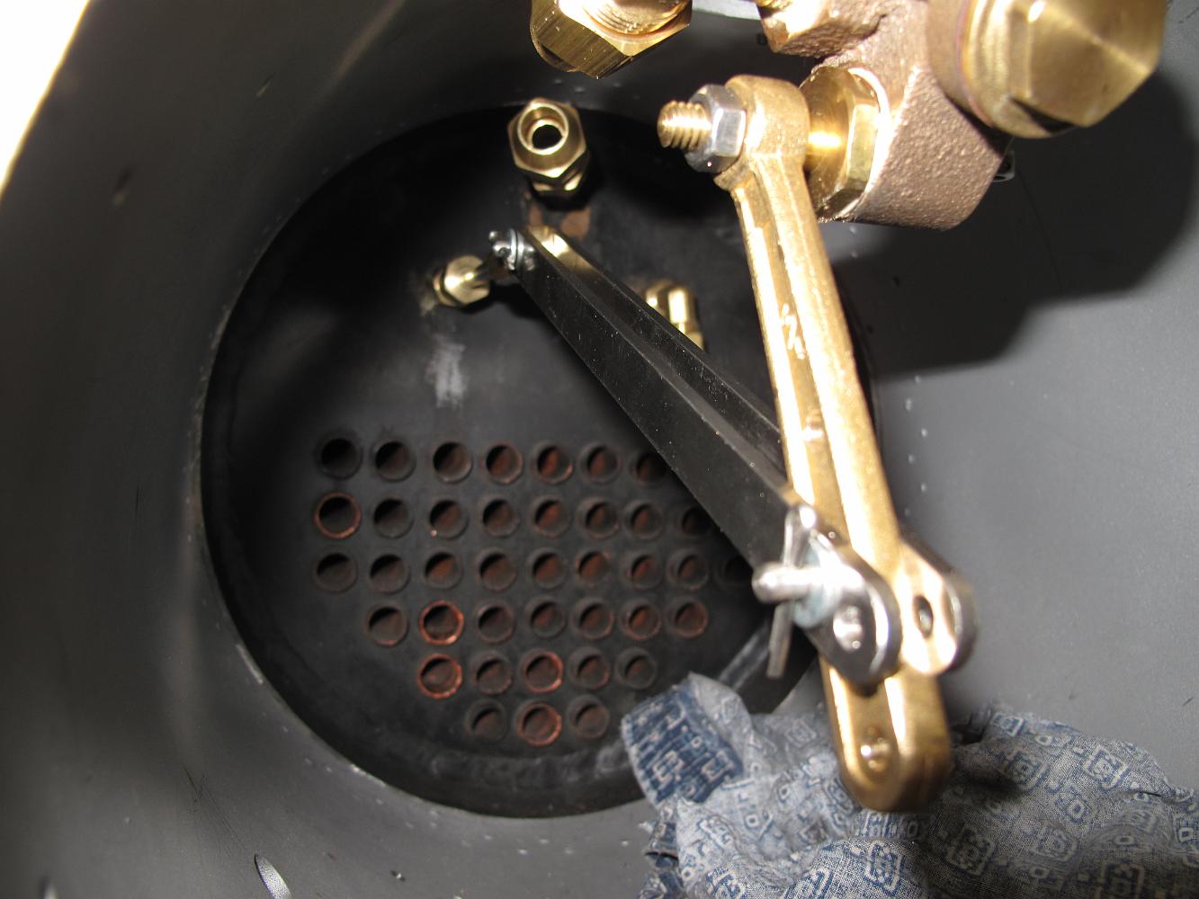
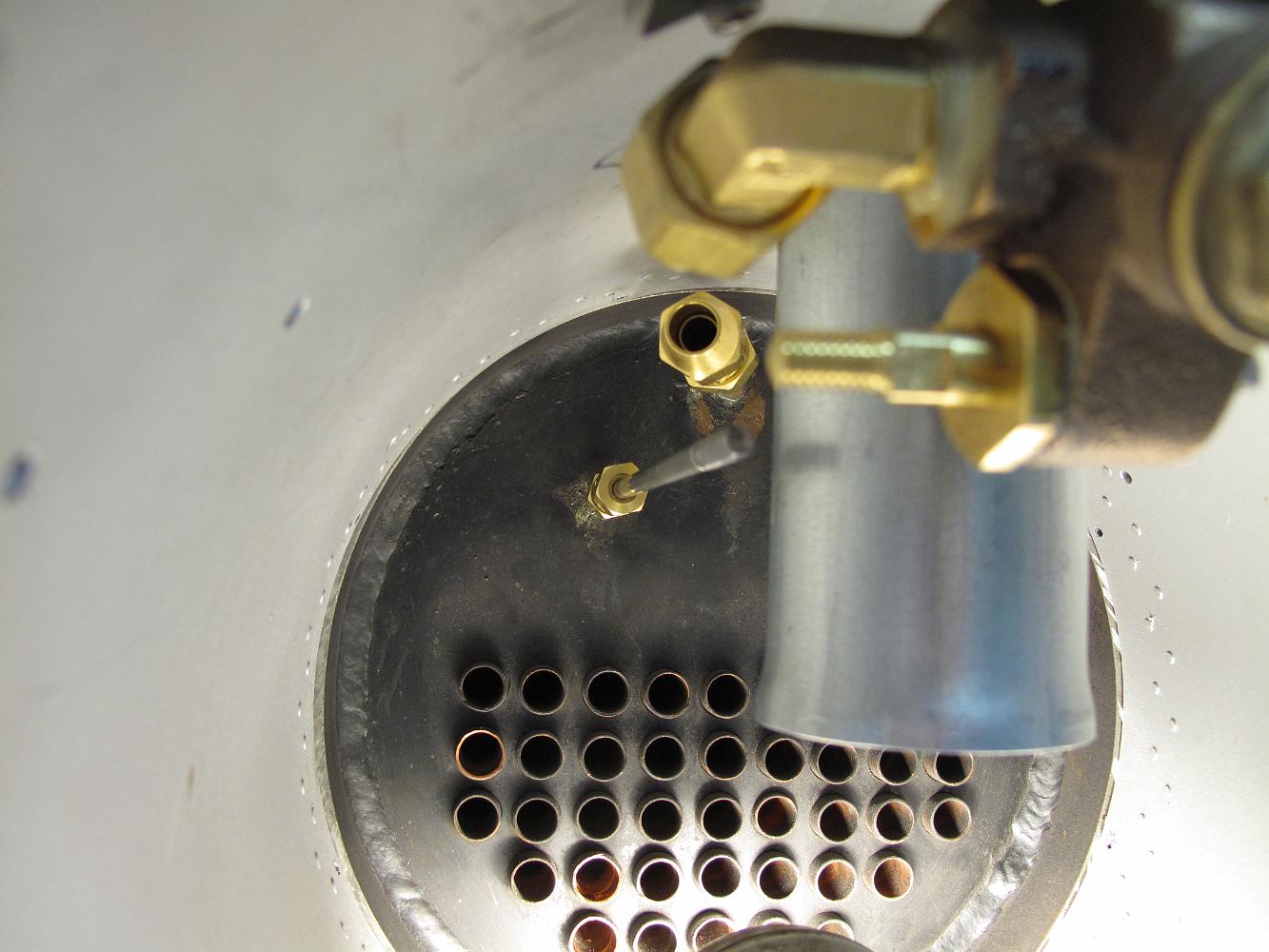
26-April-2011 The throttle bracket is installed in the smokebox and the throttle linkage arms fabricated out of stainless steel. We left a couple different…
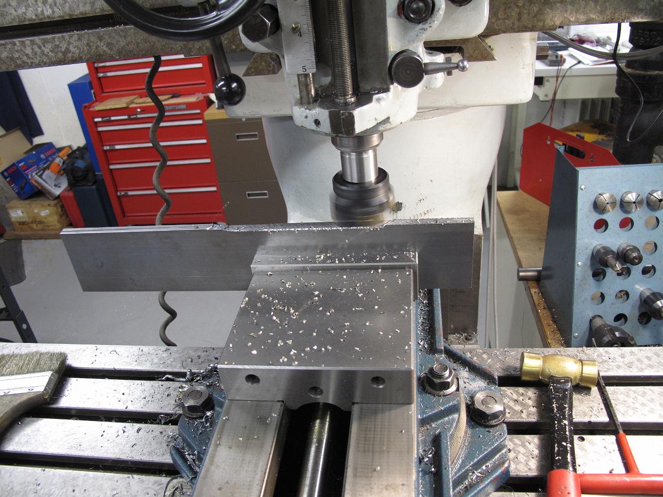
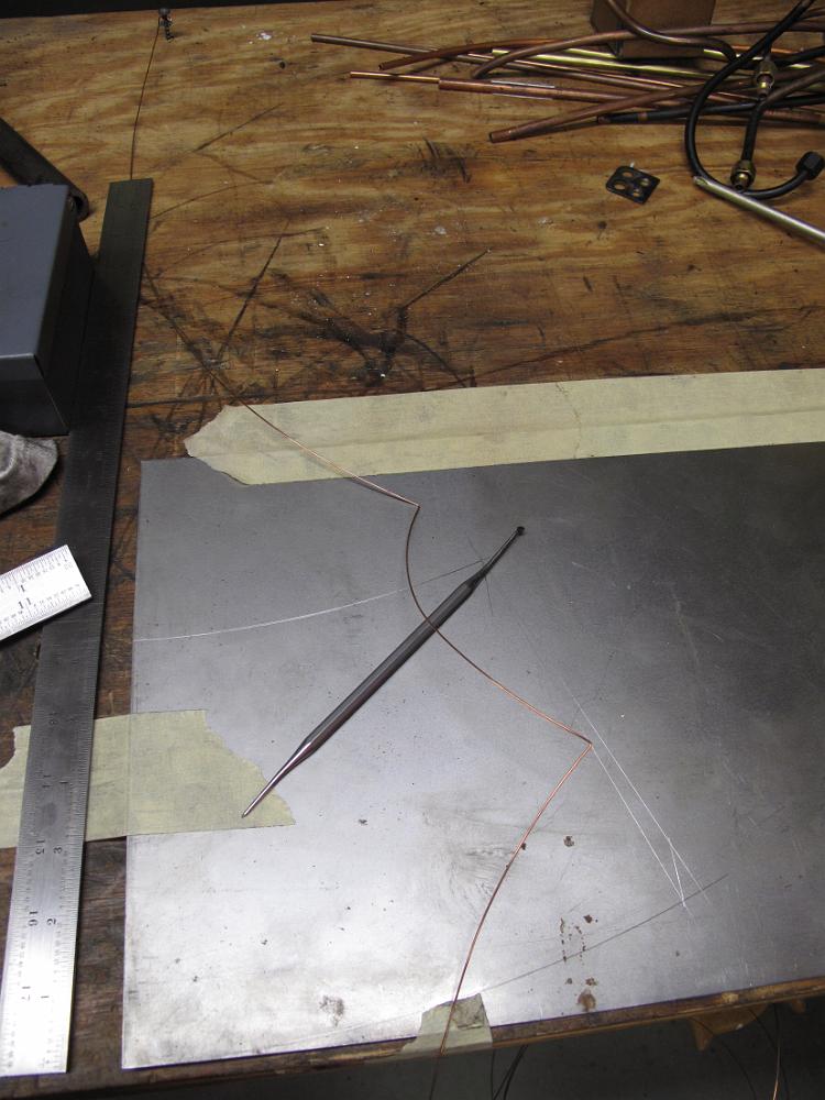
20-Apr-11 This could be a real 'Whatizit?' shot. Using a small rod inserted into the inside of the 1/2" copper main steam line, we have bent the steam line off…
19-Apr-11 A SMAW (Mig) welder sure is nice! A couple of tack welds on each side and the bottom of the tabs, and the petticoat is done!
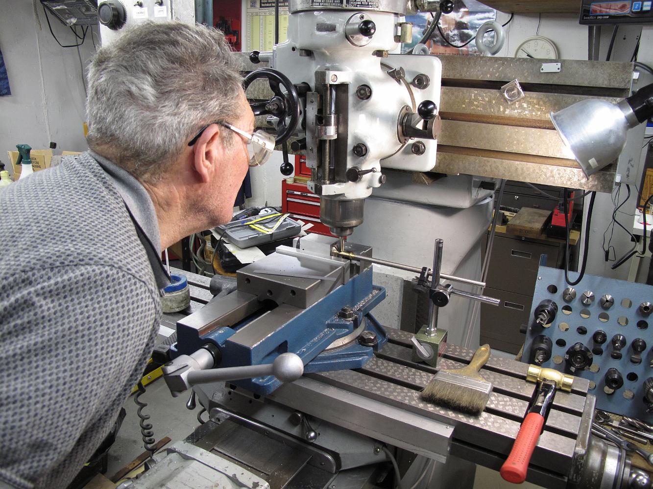
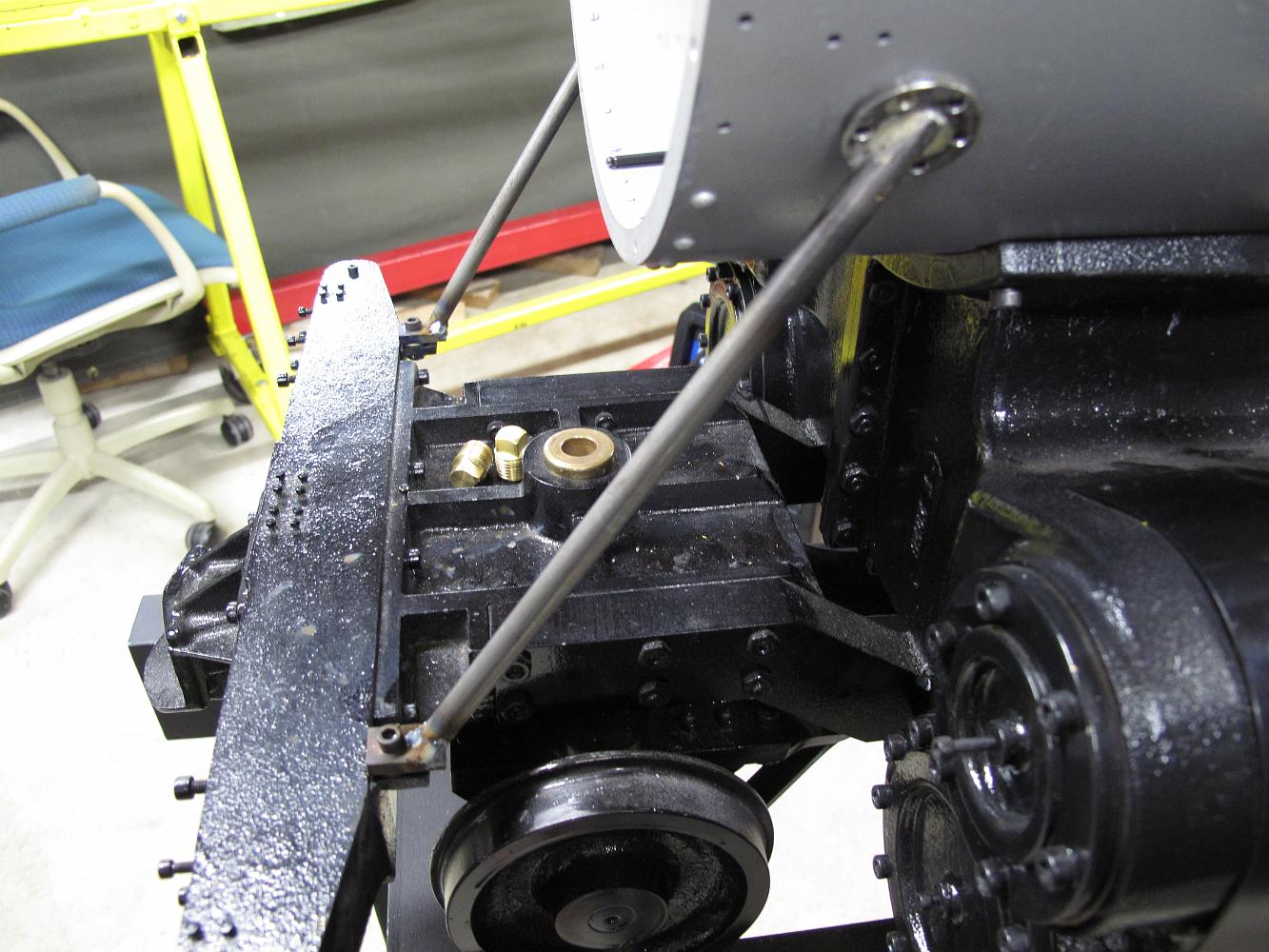
19-Apr-2011 I fussed with the little tabs which get welded on the petticoat while bill was making the throttle rod bushing. The stack is bolted down to the…
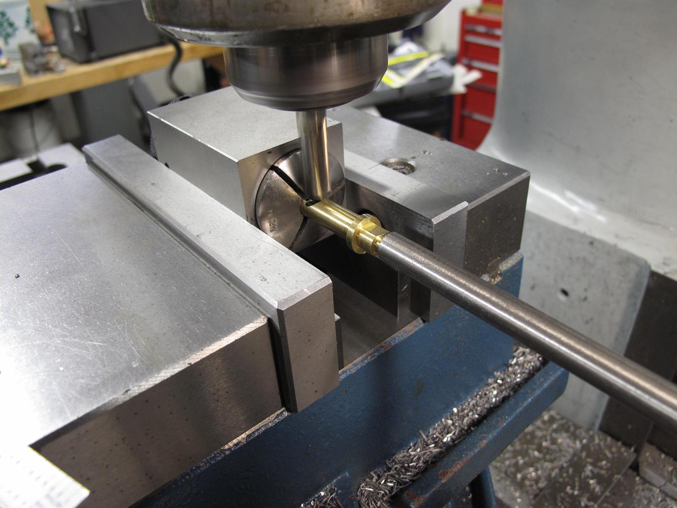
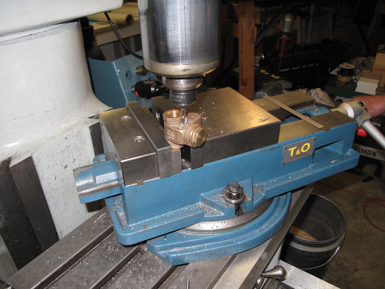
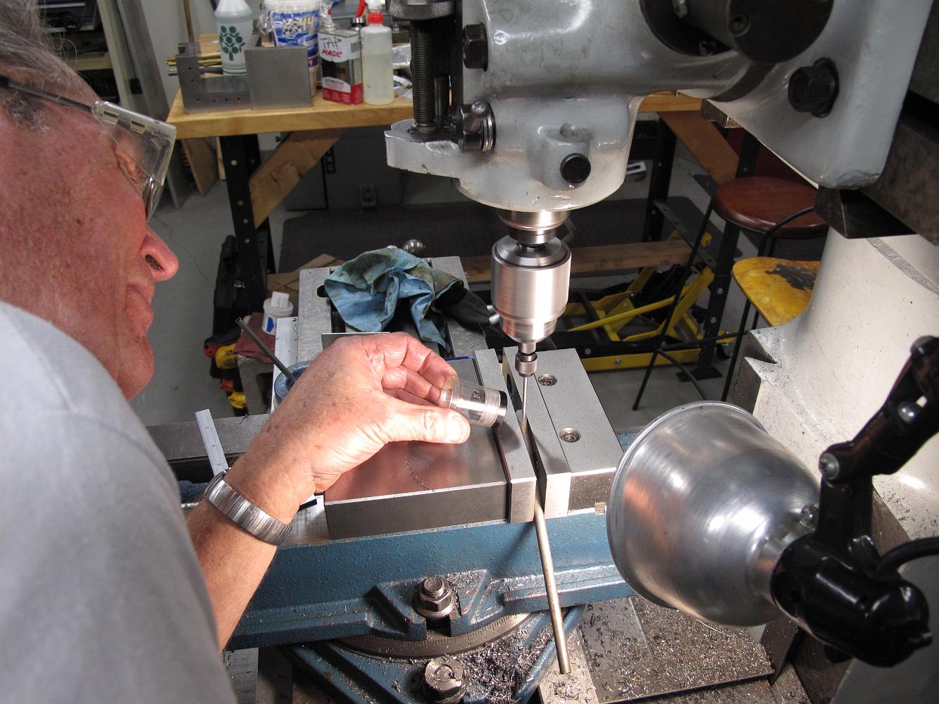
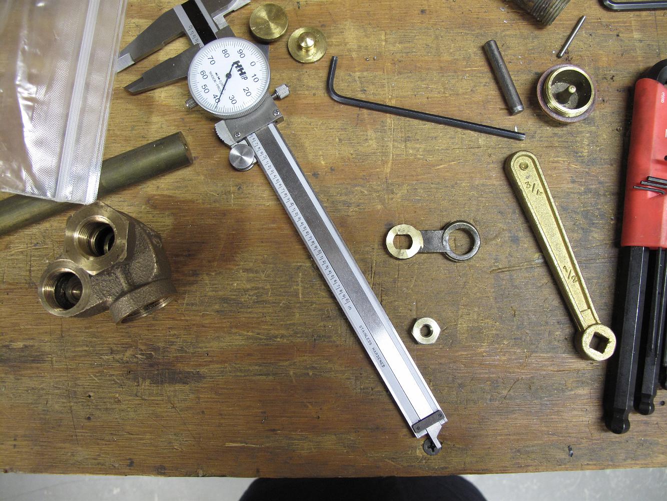
19-Apr-11 bill turned a piece of bronze to make a bushing for the throttle rod. We are using a commercial 3/8 to 3/8 compression tube fitting because the…
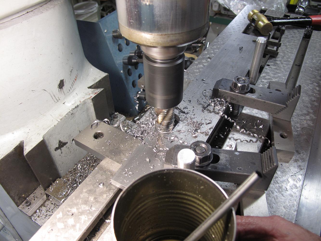
11-Apr-11 Drilling the throttle bracket mounting holes in the shell. The holes will be 10-32 tapped into the boiler shell, so we are drilling with a tap-size…
2-Apr-11 The throttle bracket temporarily held in position for drilling with long reach welding clamps. Note the 'Single-use' petticoat - made of cardboard. I…
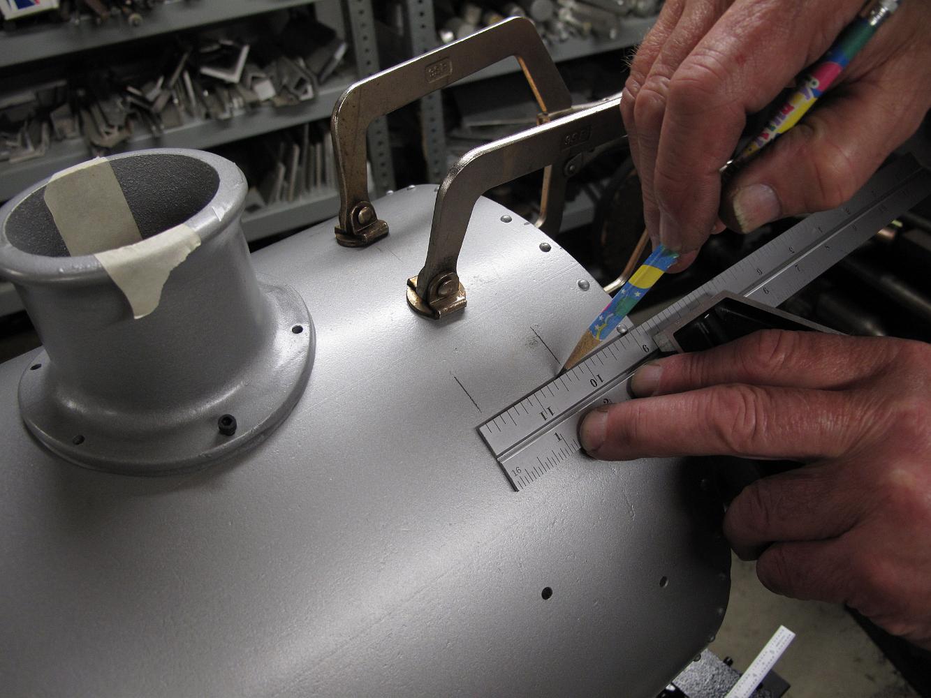
12-Apr-2011 Bill lays out where the throttle mounting bracket will be inside the smokebox, in preparation to drill mounting holes.
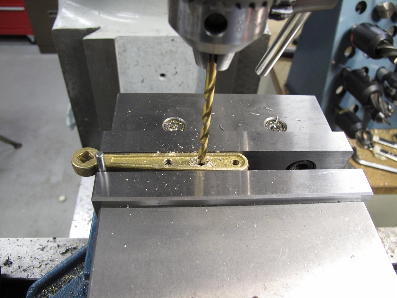
5-Apr-2011 with the flats milled in, the clevis has a nice rounded end from the corner rounding bit.
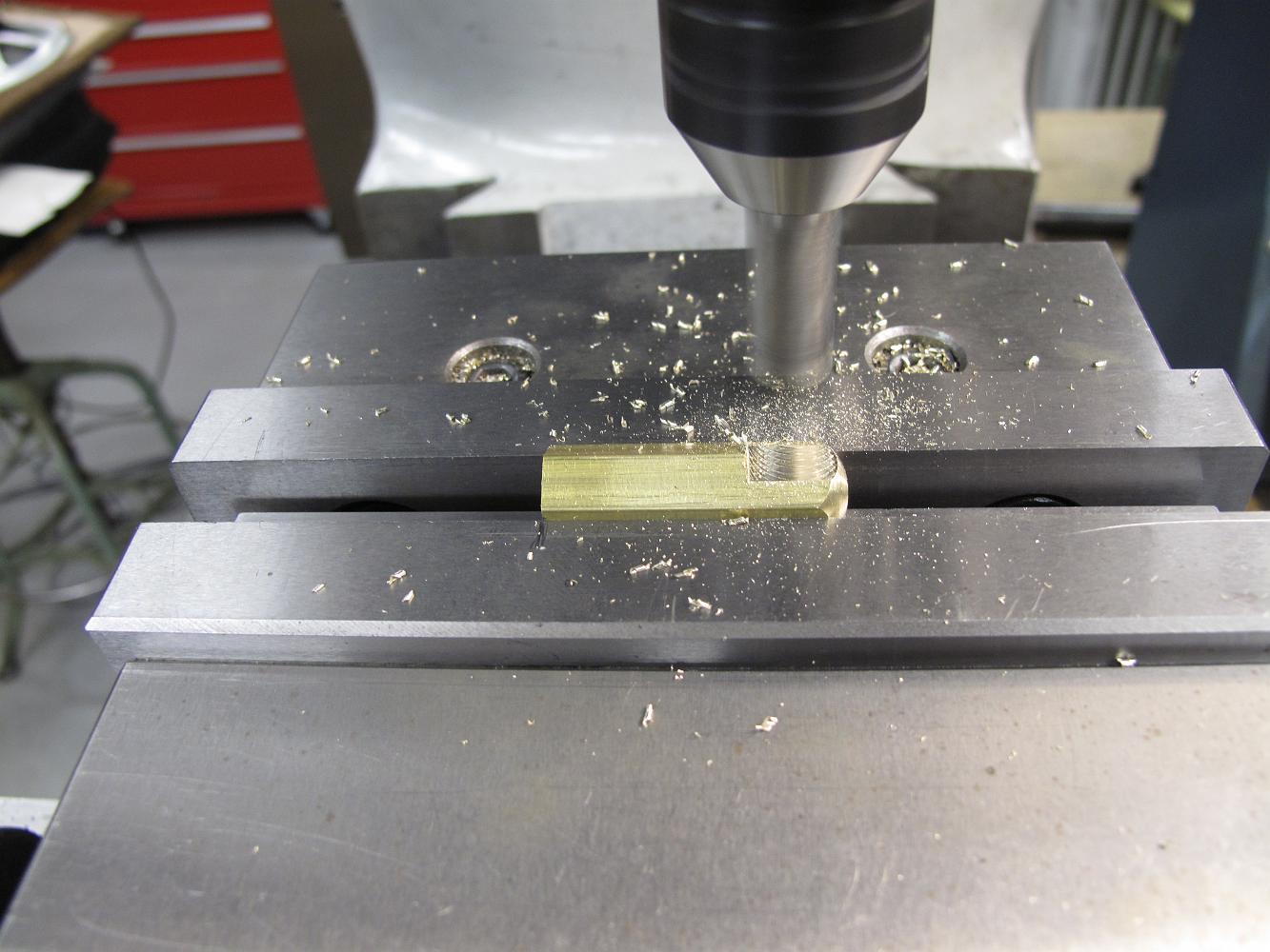
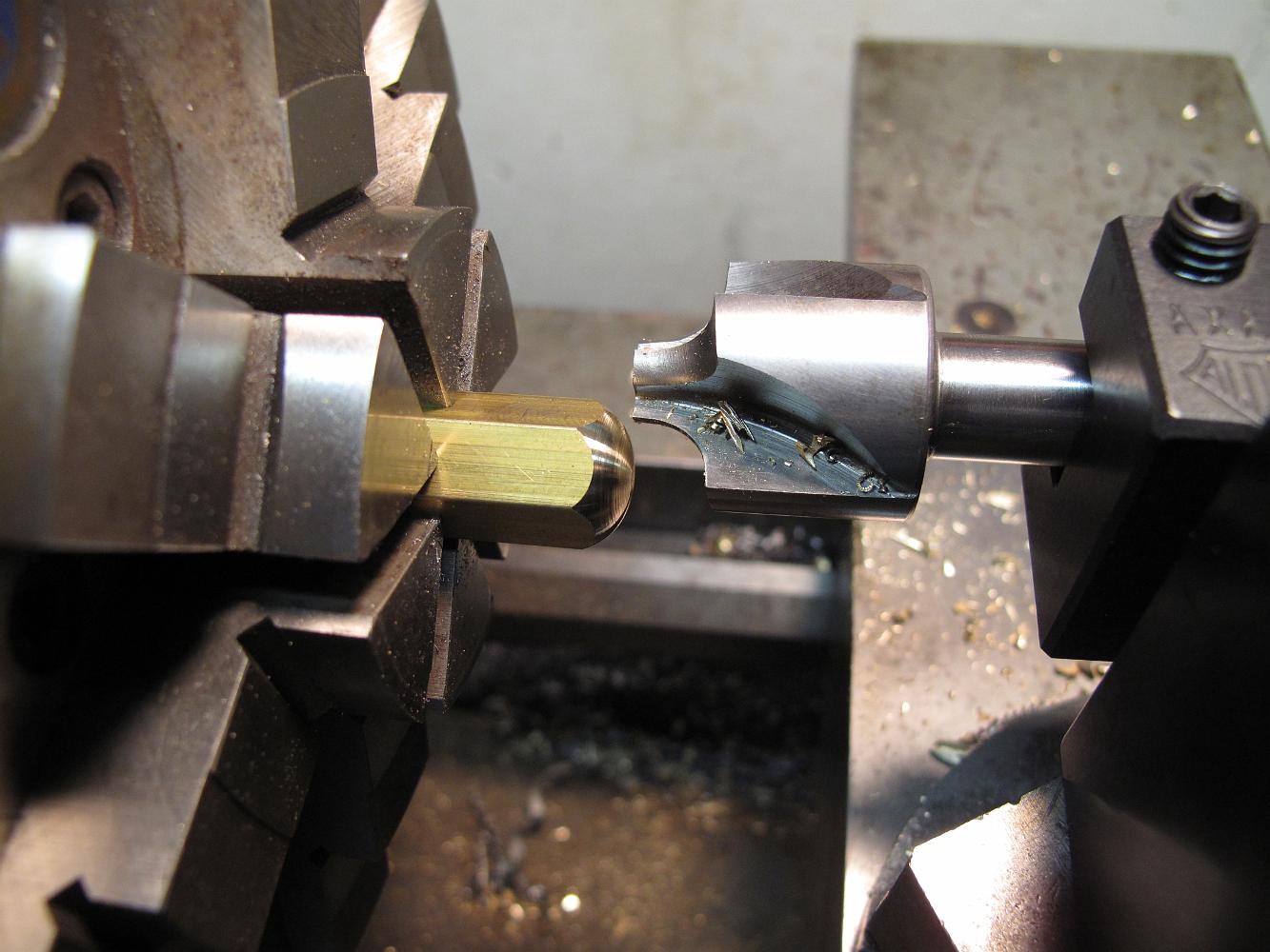
The set up of the corner rounding bit in the tool holder. Getting the center height correct is important!
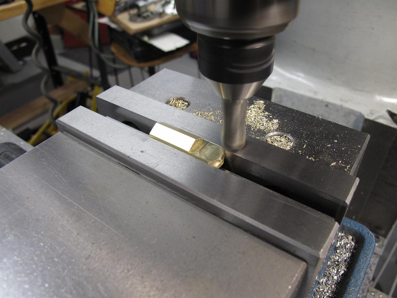
5-Apr-2011 We decided to make our own throttle clevis, using 7/16" brass hex stock on hand. here Bill is putting a nice radius on the end of the clevis using a…
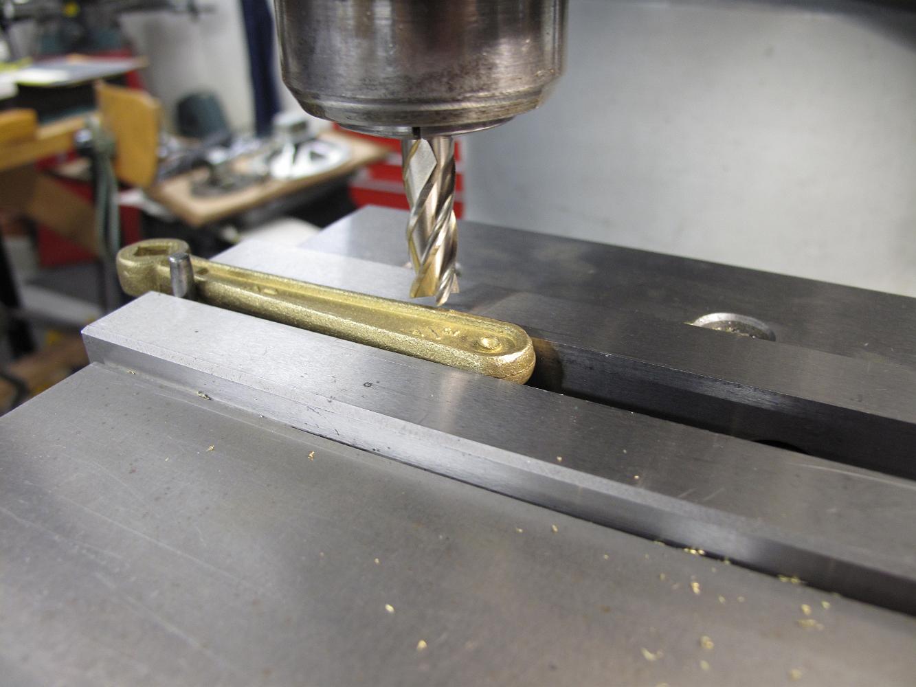
After some hand dressing of the rudely broached handle, we have a nice, no slop fit. The throttle stem and handle that came with the valve were slop and would…
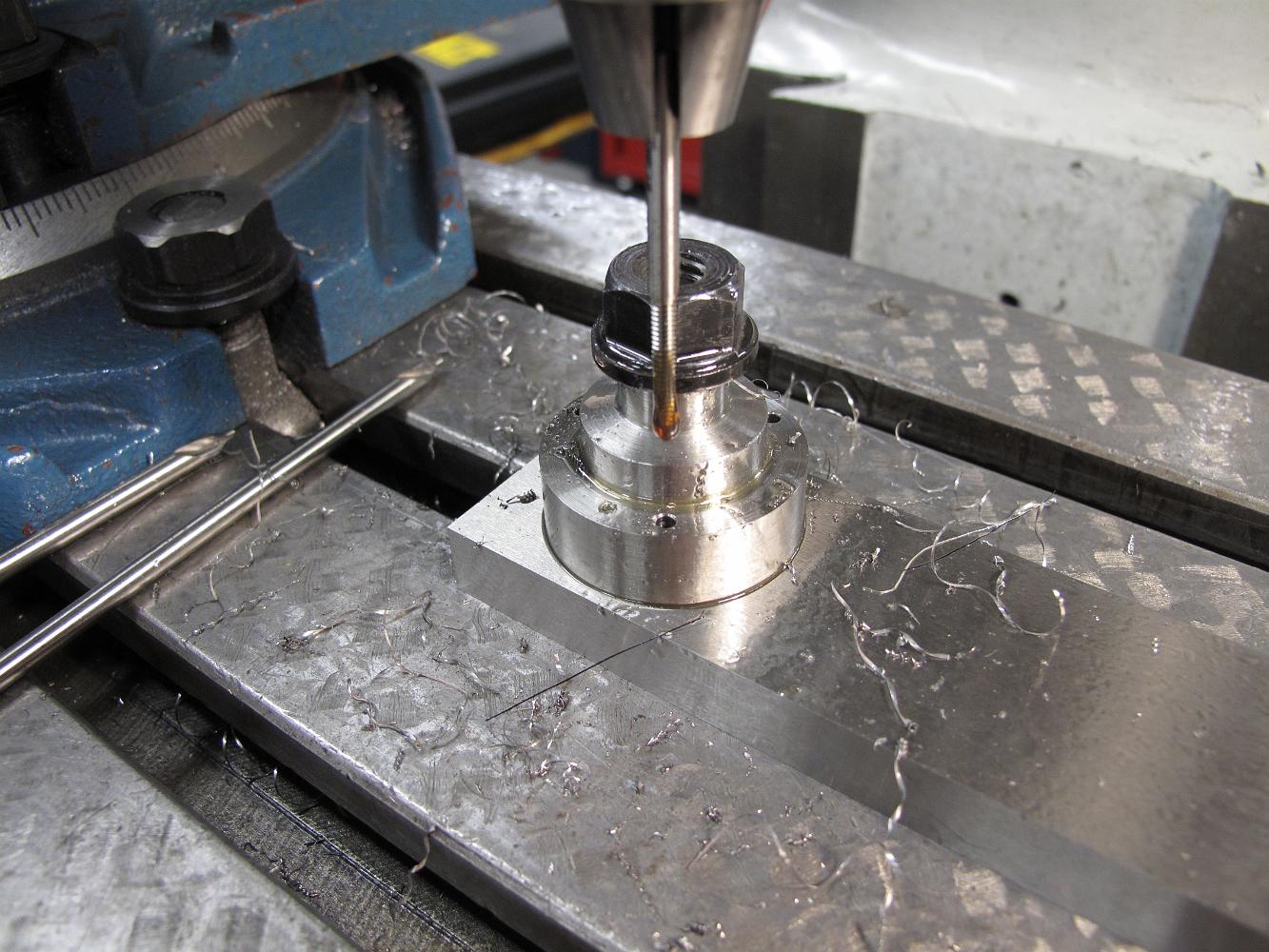
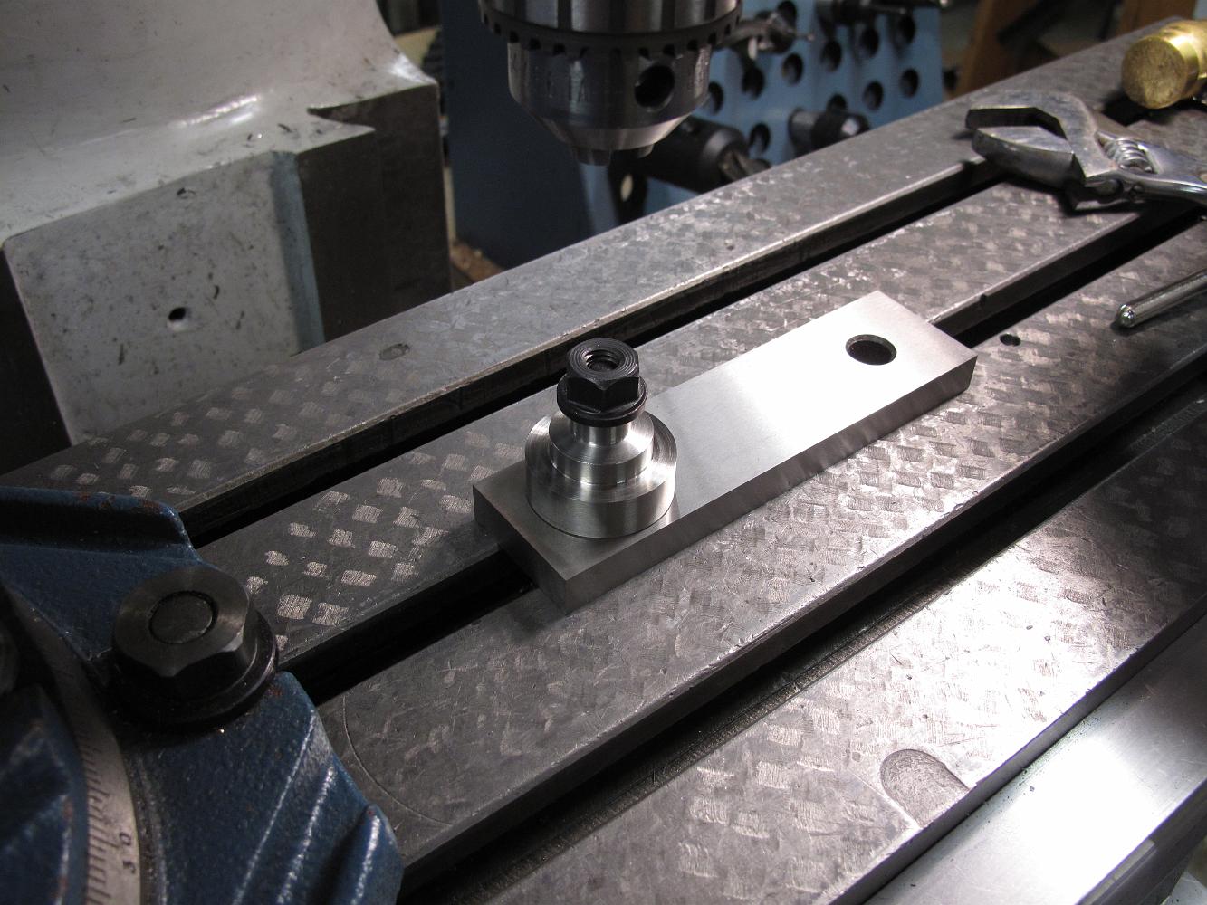
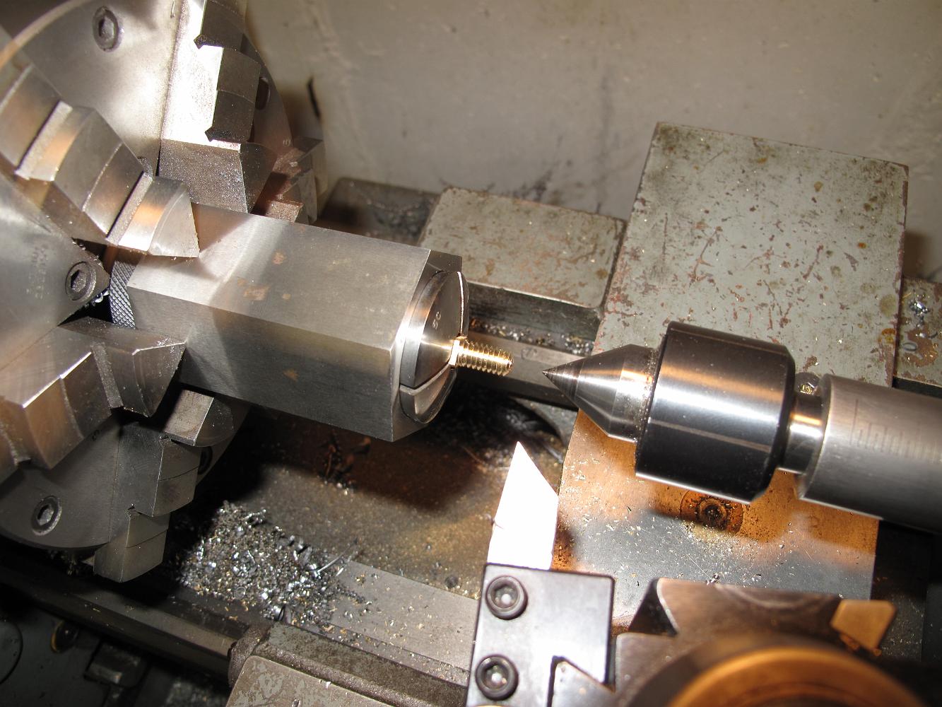
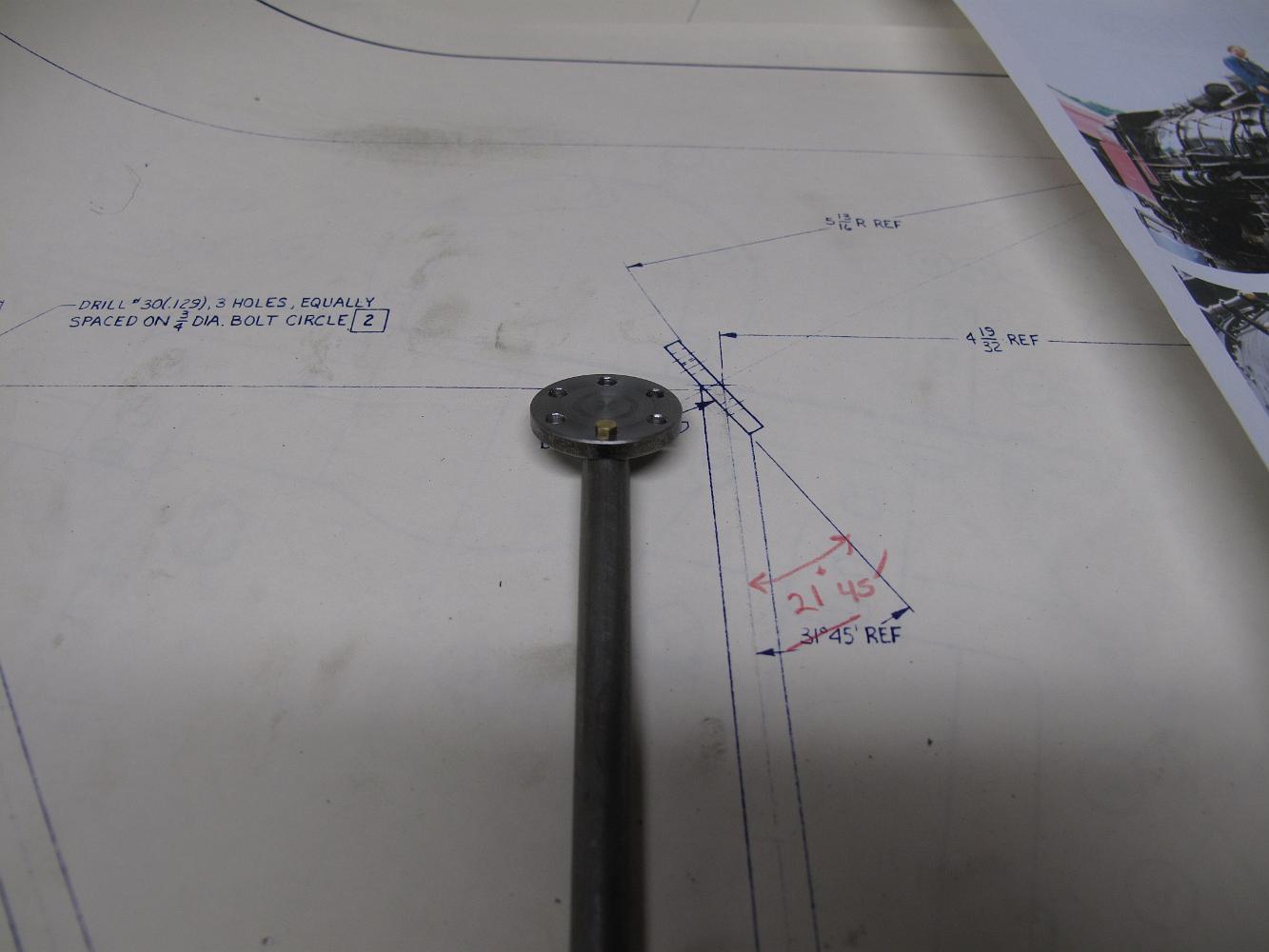
29-Mar-2011 with the throttle brack completed, we are able to determine how long our replacement valve stem should be. We set the length and machine the four…
29-Mar-2011 with the throttle brack completed, we are able to determine how long our replacement valve stem should be. We set the length and machine the four…
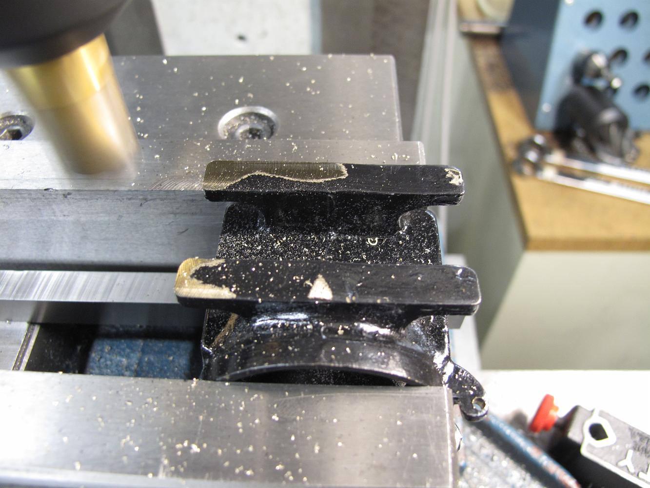
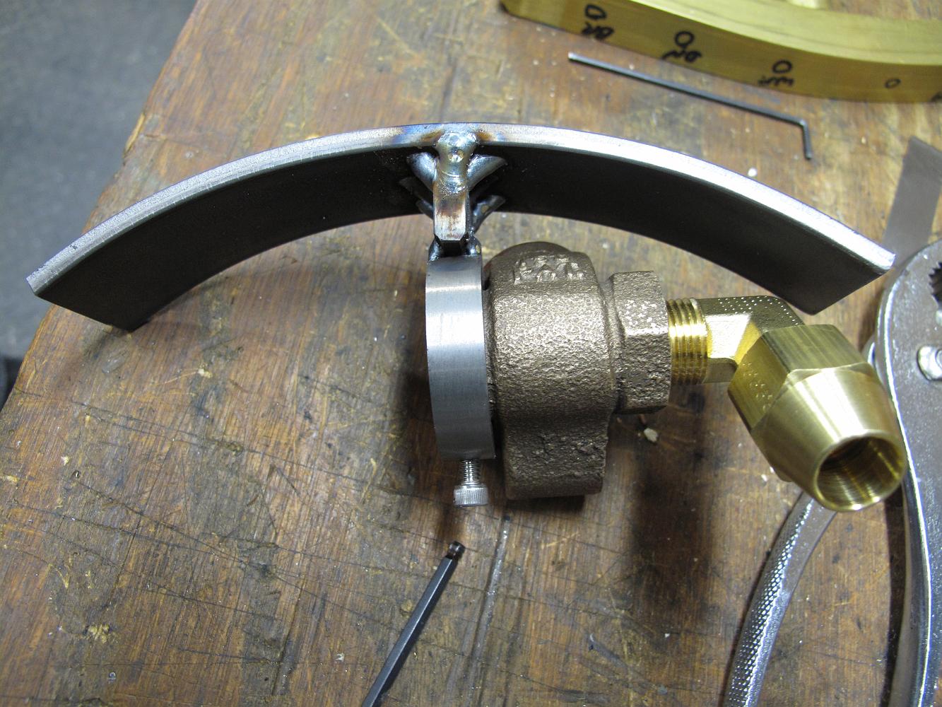
29-Mar-2011 We have bent a piece of flat stock to match the inside curve of the smokebox. this assembly will be bolted to top of the smokebox.
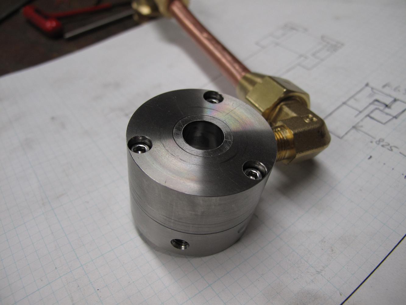
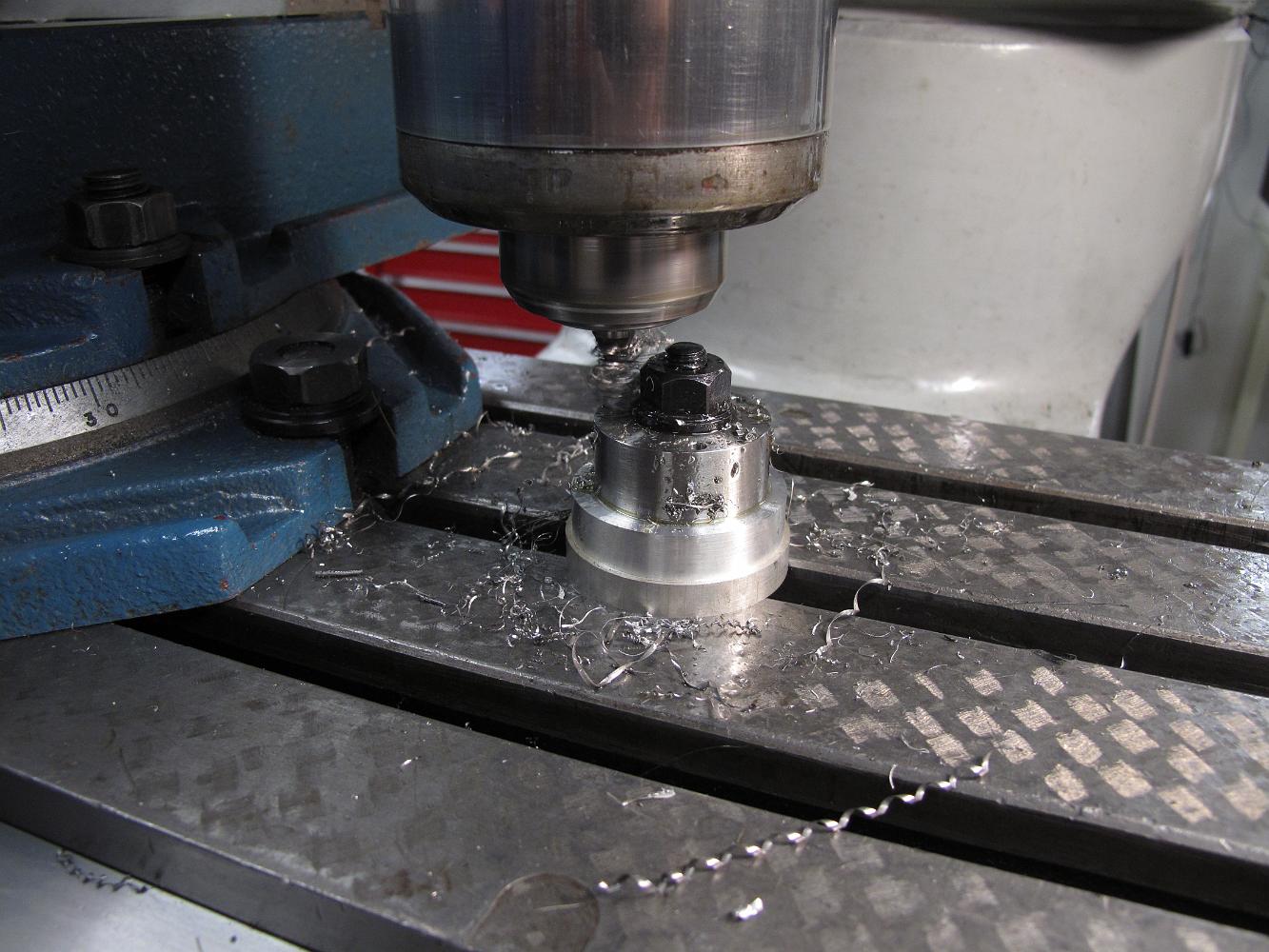
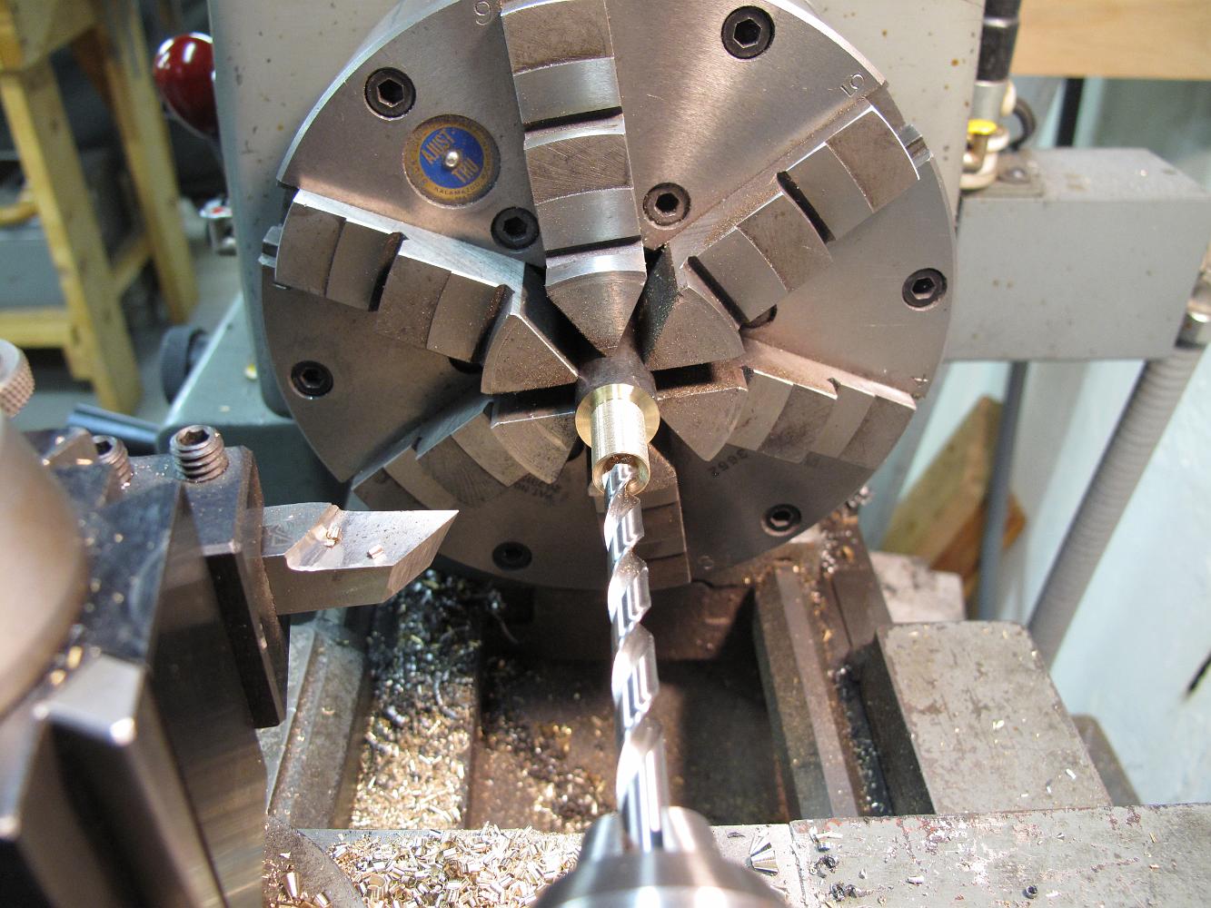
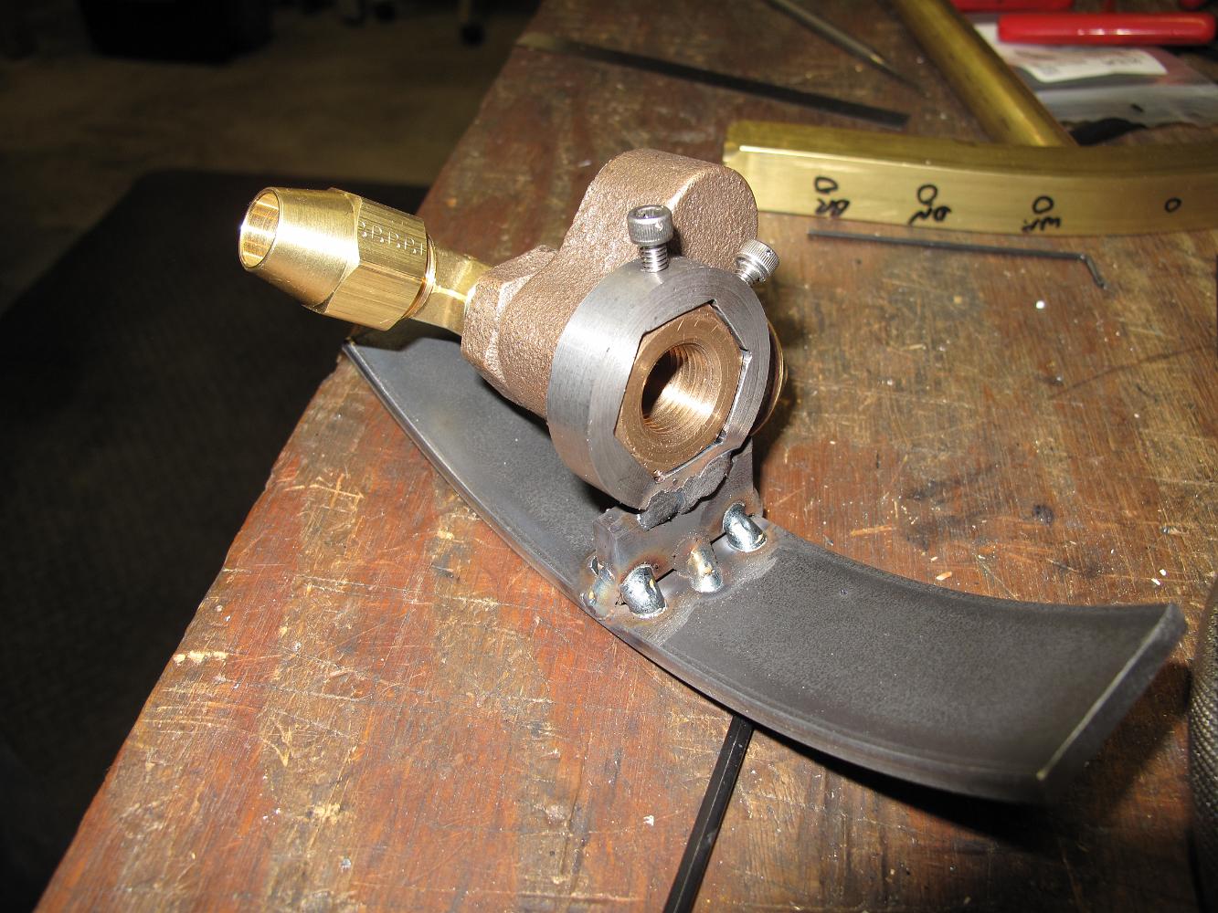
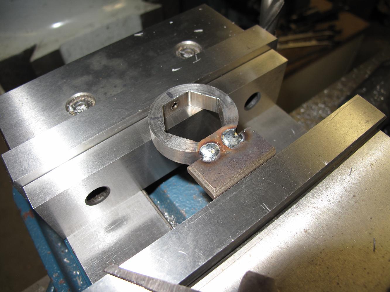
29-Mar-2011 the machined collar with two 8-32 holes drilled an tapped for set screws. I've welded a standoff on the collar, we're about to machine the welds…
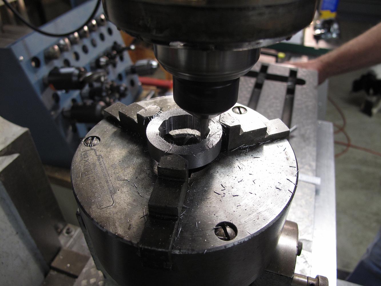
26-Mar-2011 machining a collar out of steel, inside profile is a hexagon to match the valve. We use the rotary table with a chuck.
26-Mar-2011 Back to work on the throttle. We have been thinking about how to mount and install this quarter turn gate valve for some time. We decide to build a…
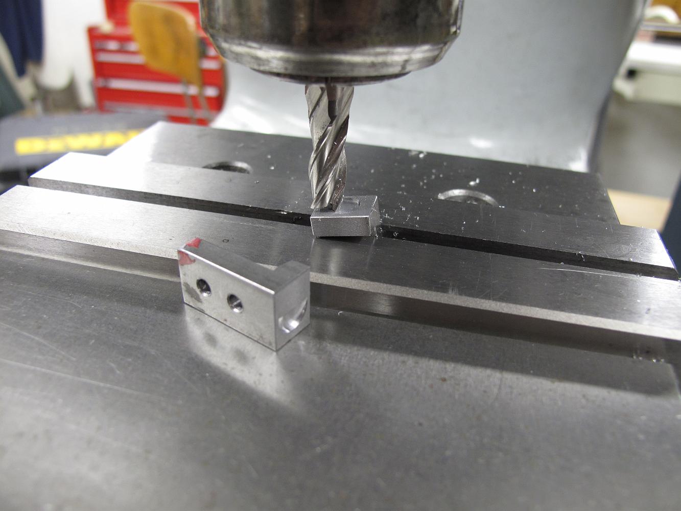
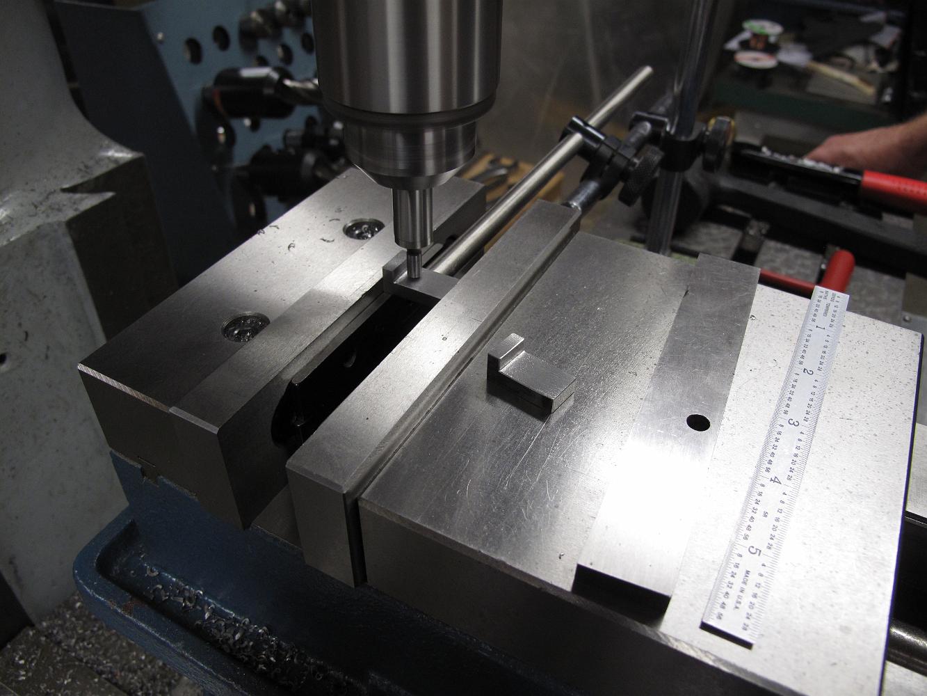
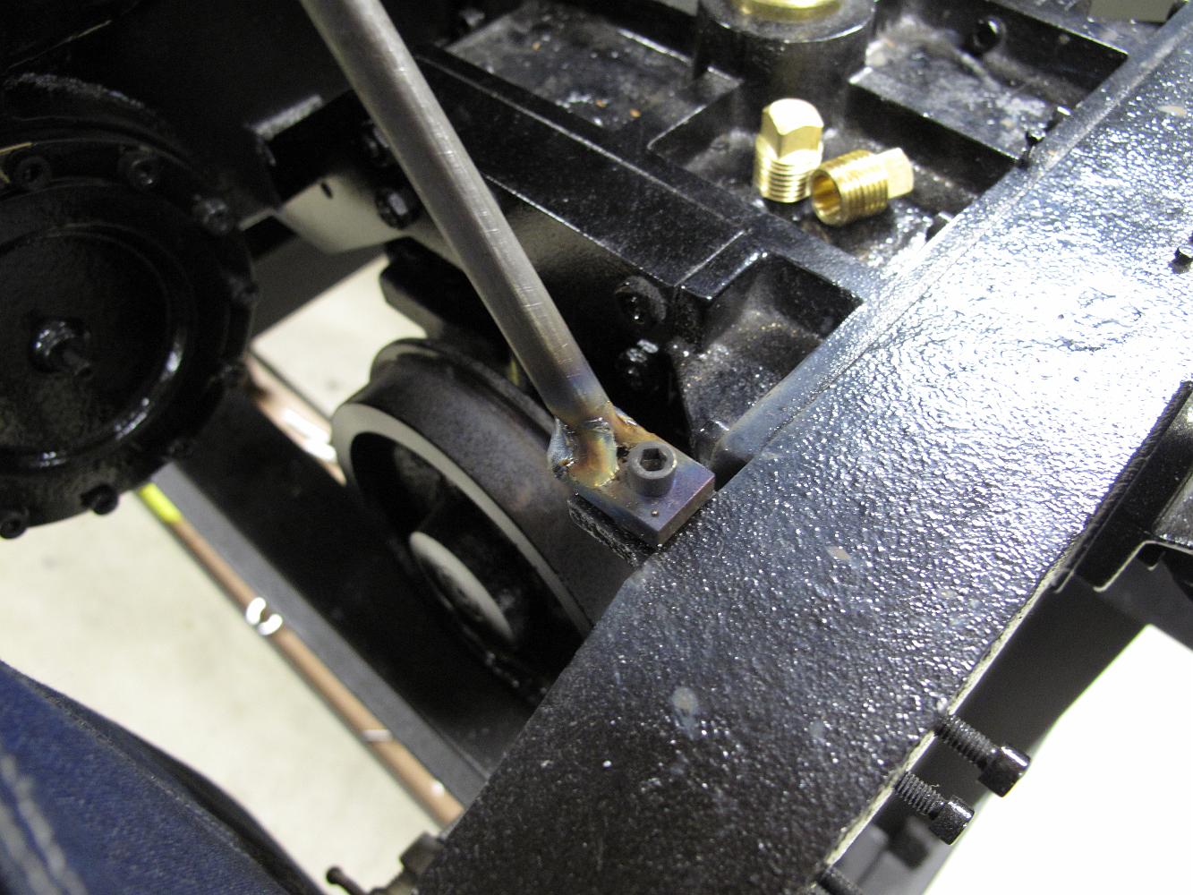
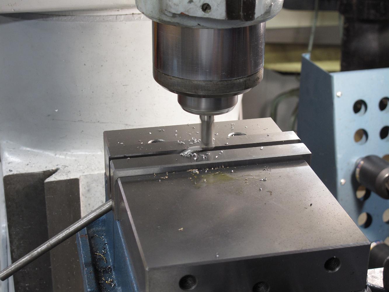
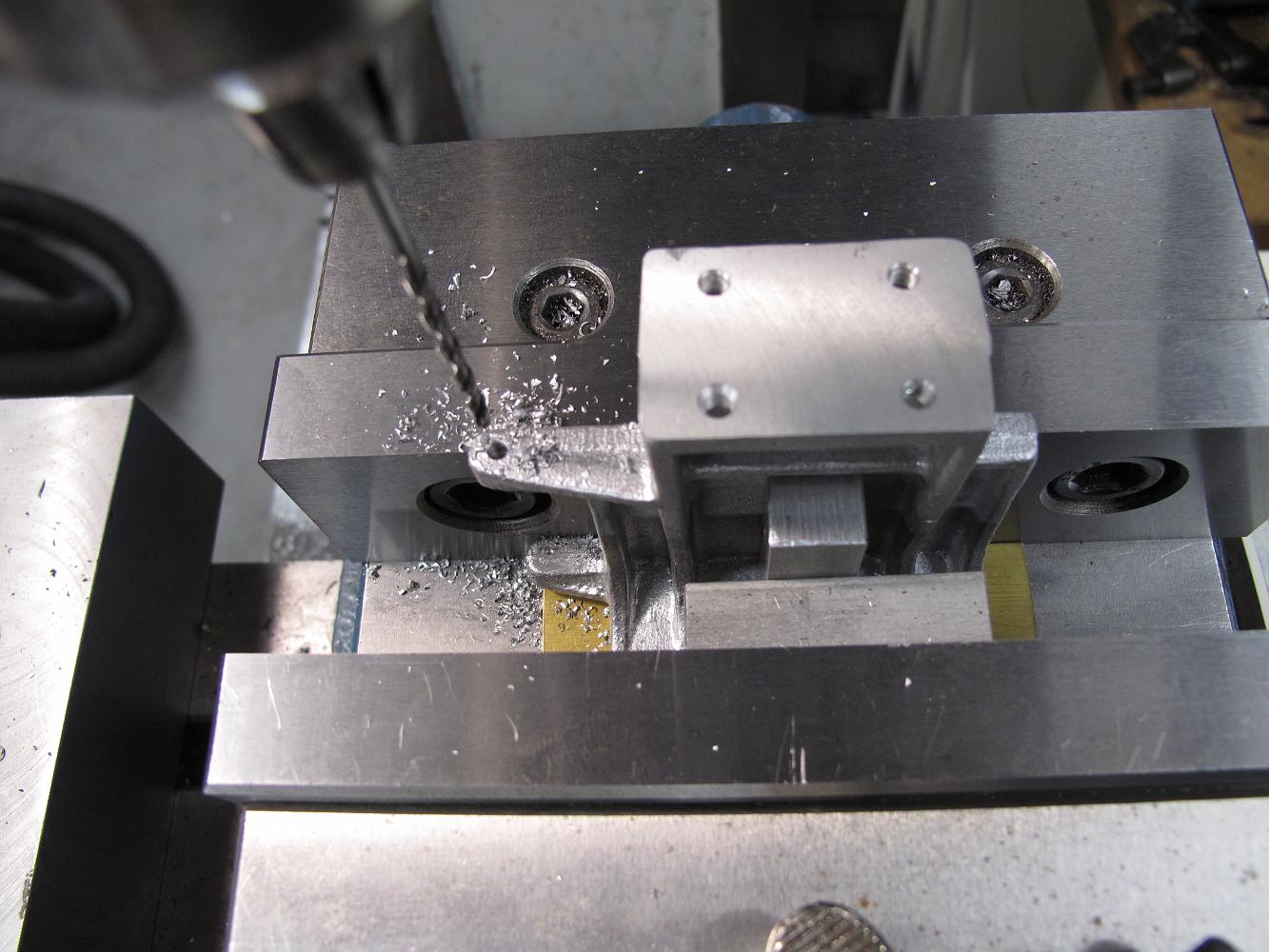
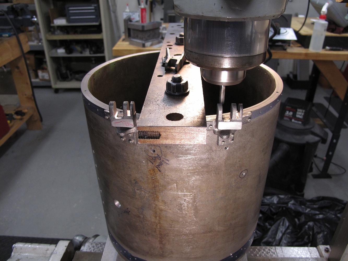
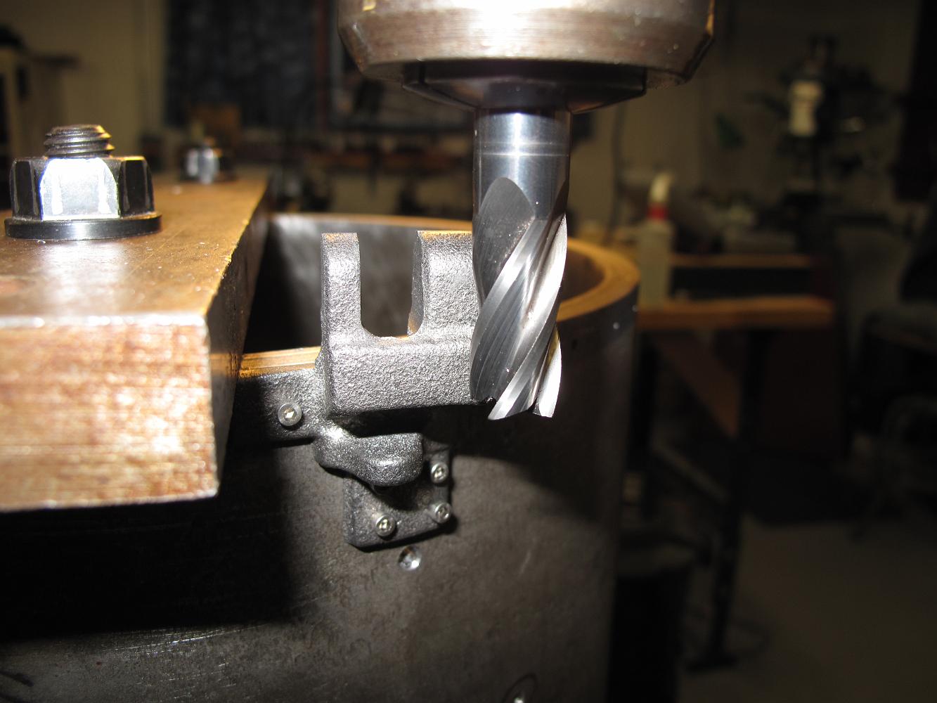
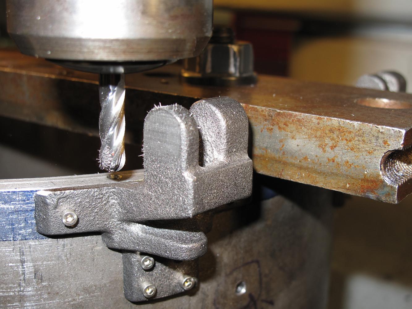
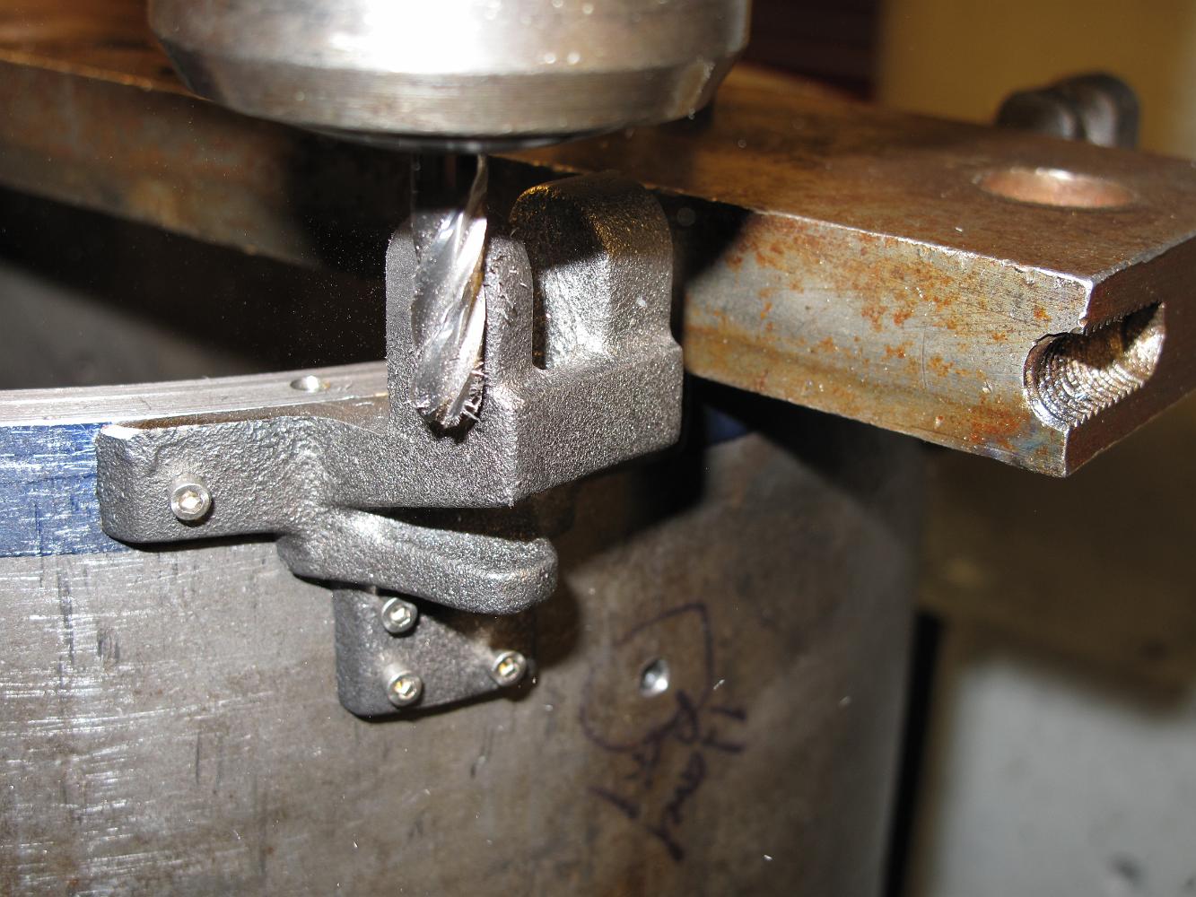
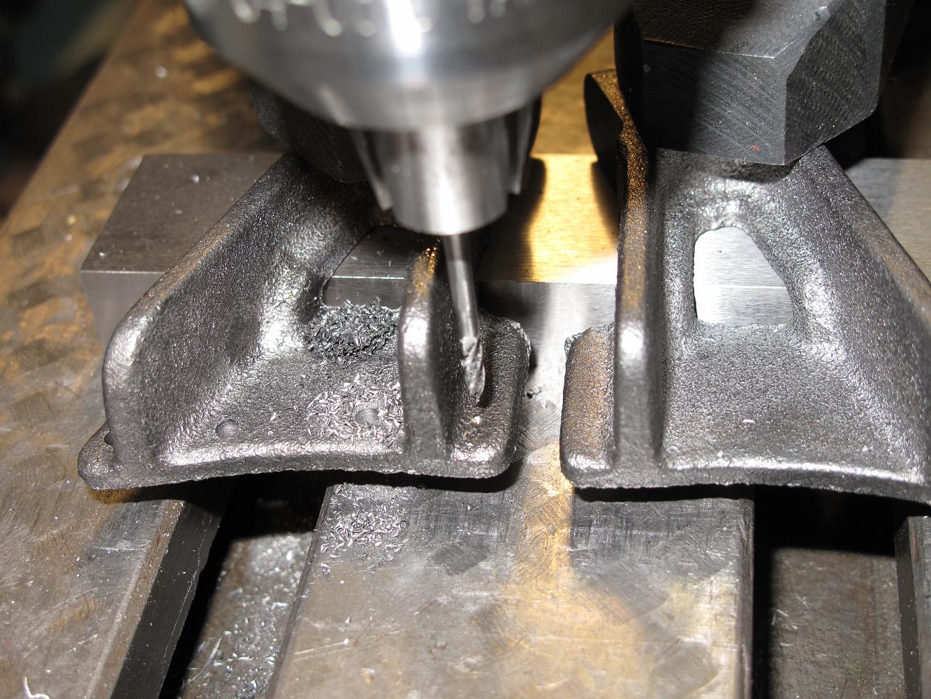
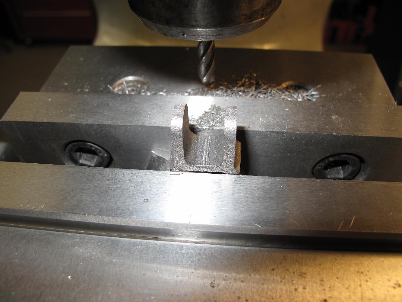
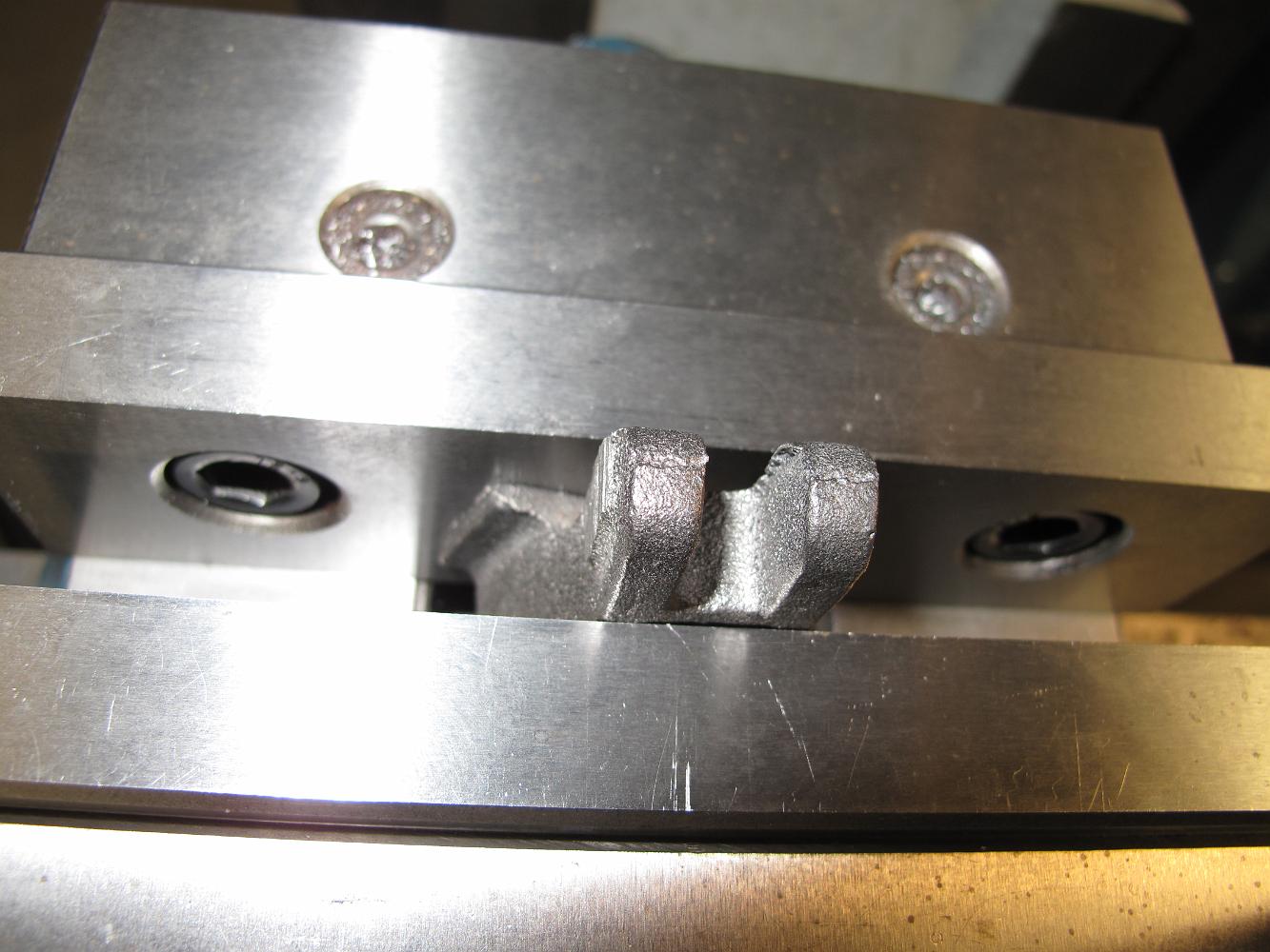
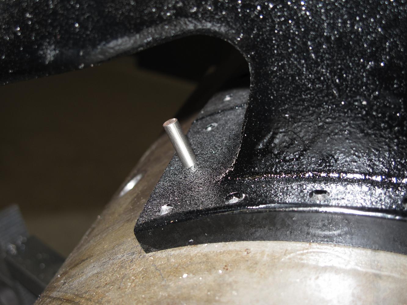
Milling a small pocket in the top of the foot for the pilot brace rod to set into. This should help stabilize the rod and keep it in position while I tack weld…
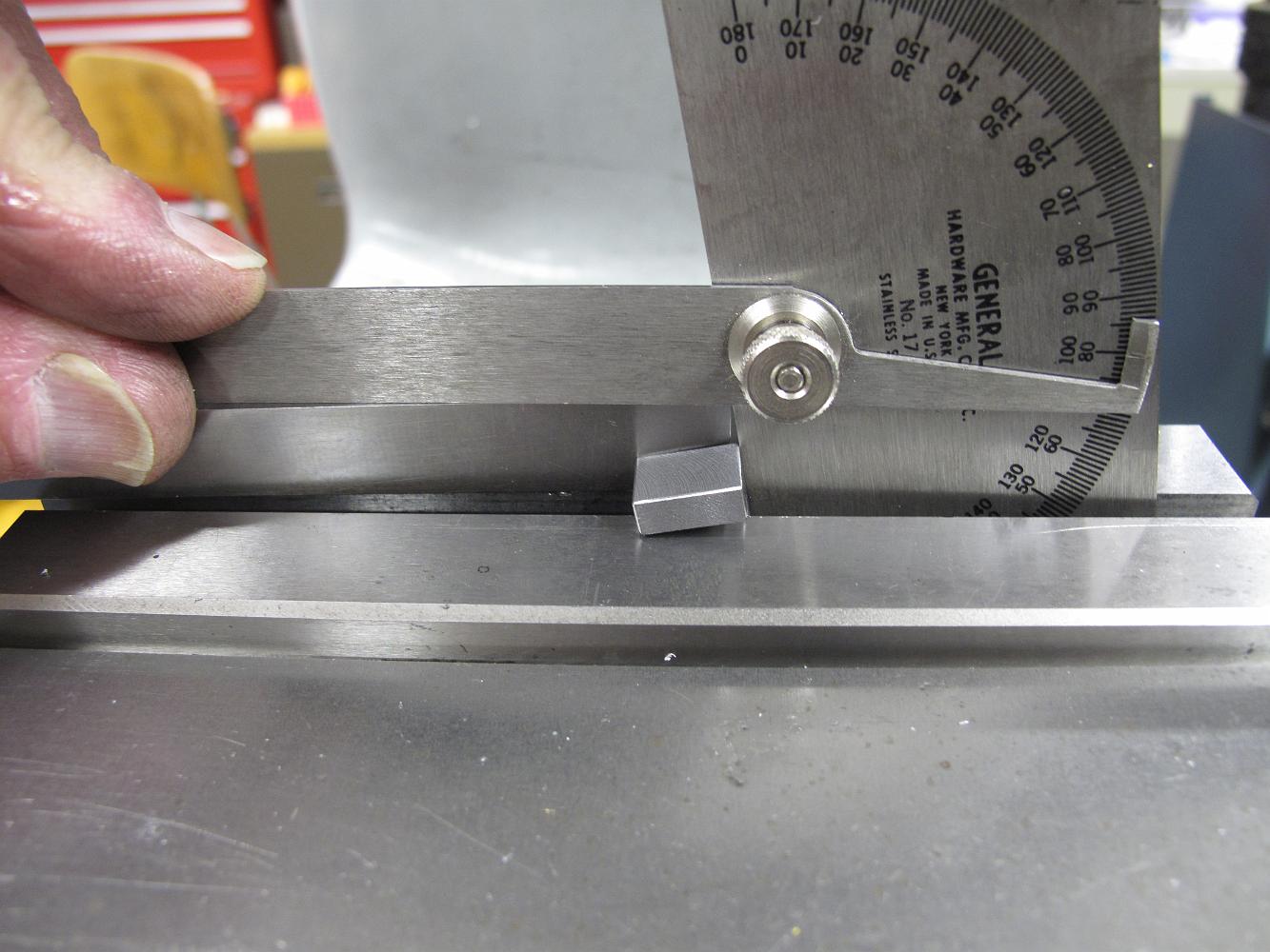
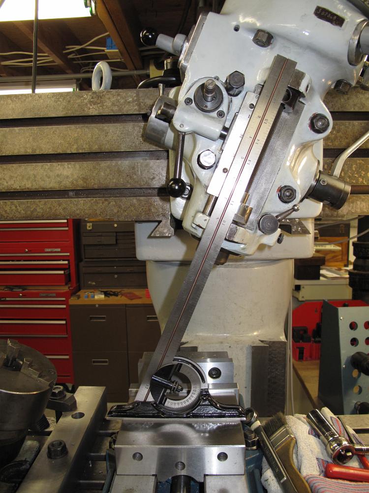
5-Jan-2011 Doing our best to match the angle of the brace rod coming down from the smokebox with the machinists protractor.
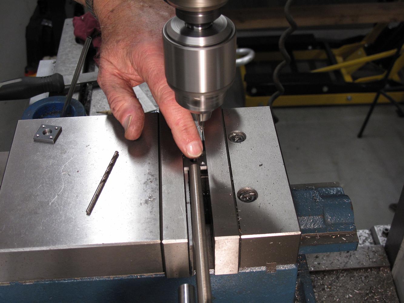
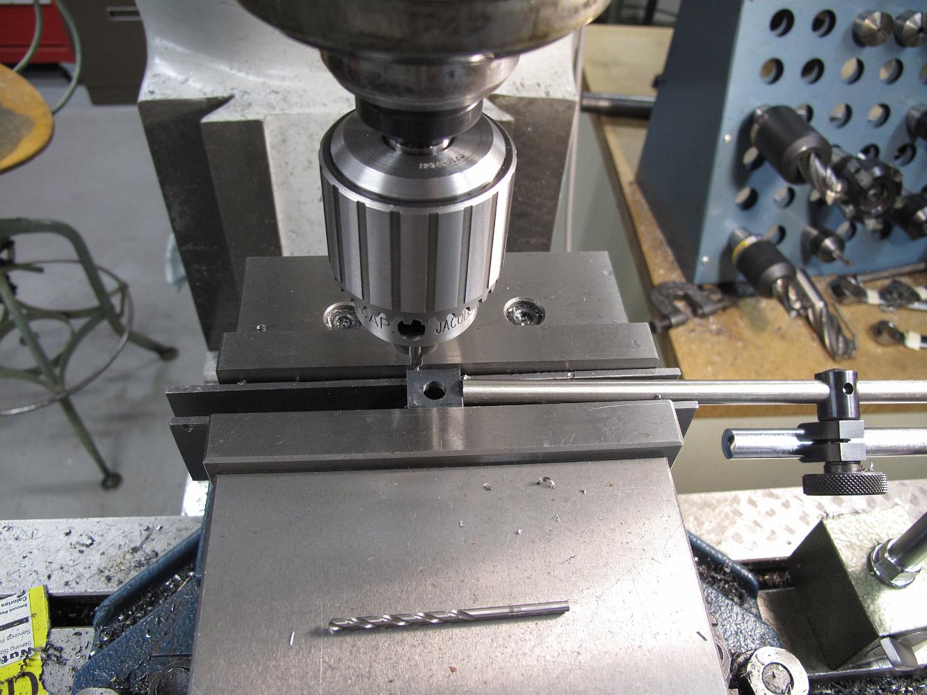
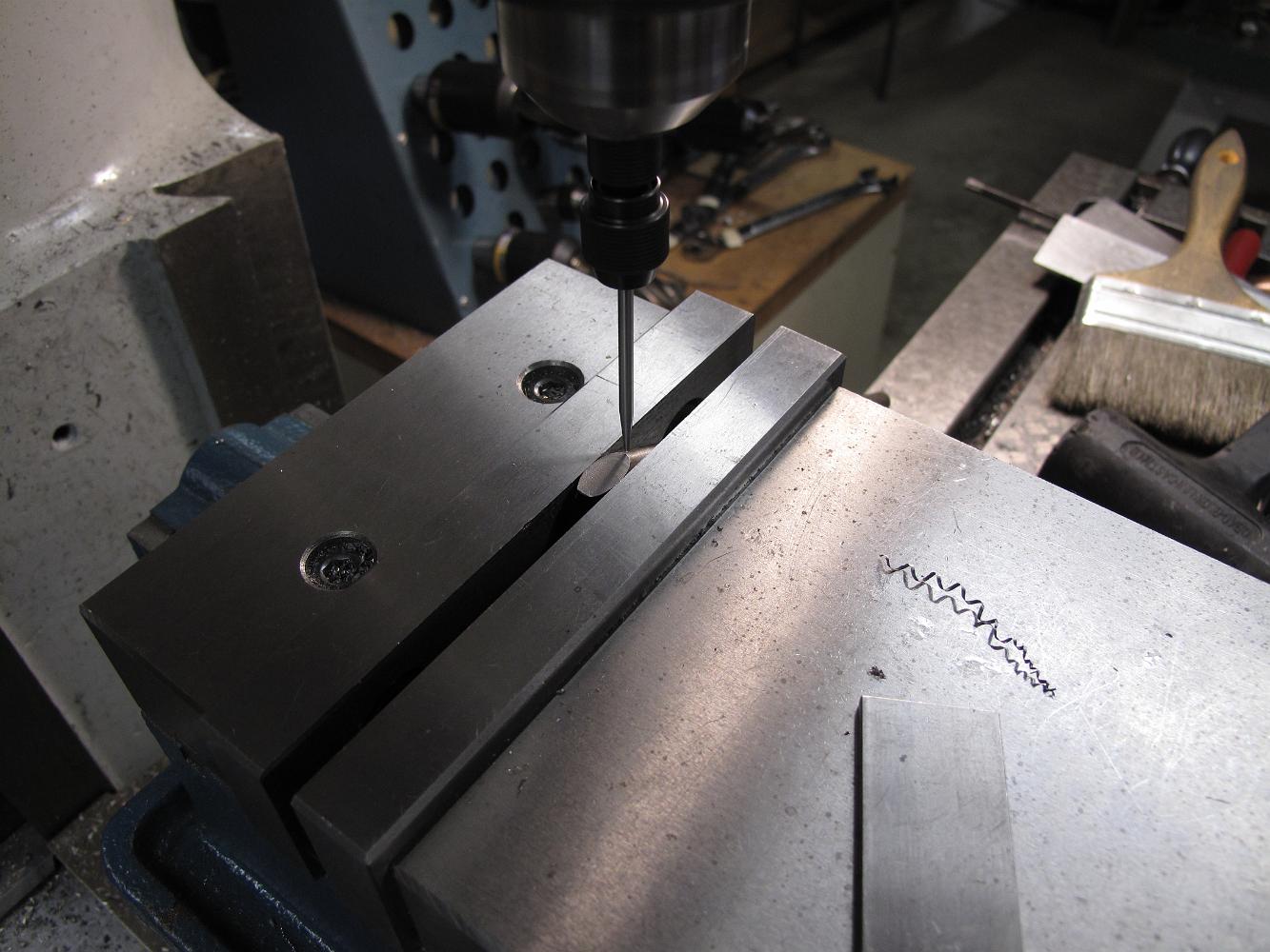
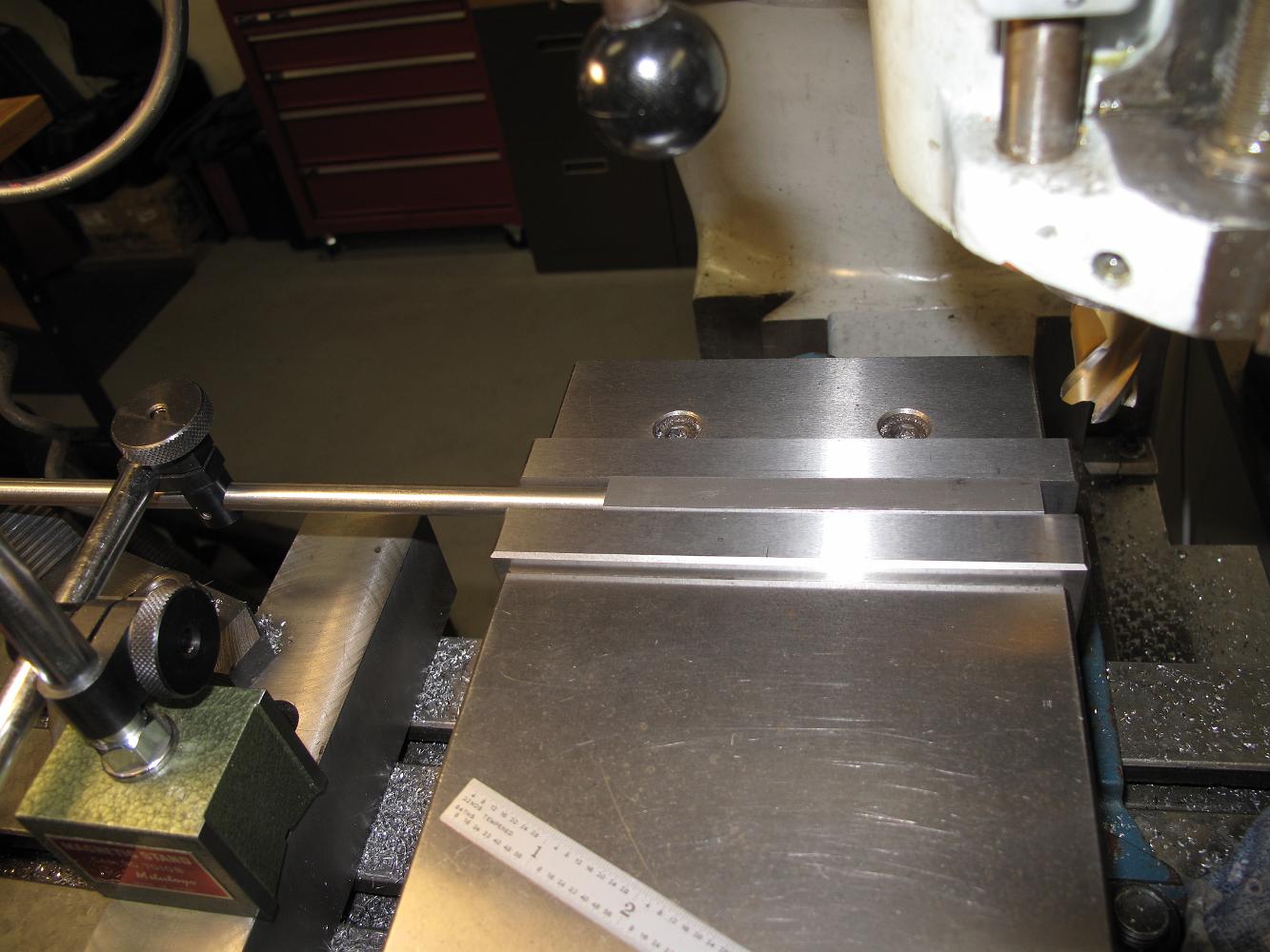
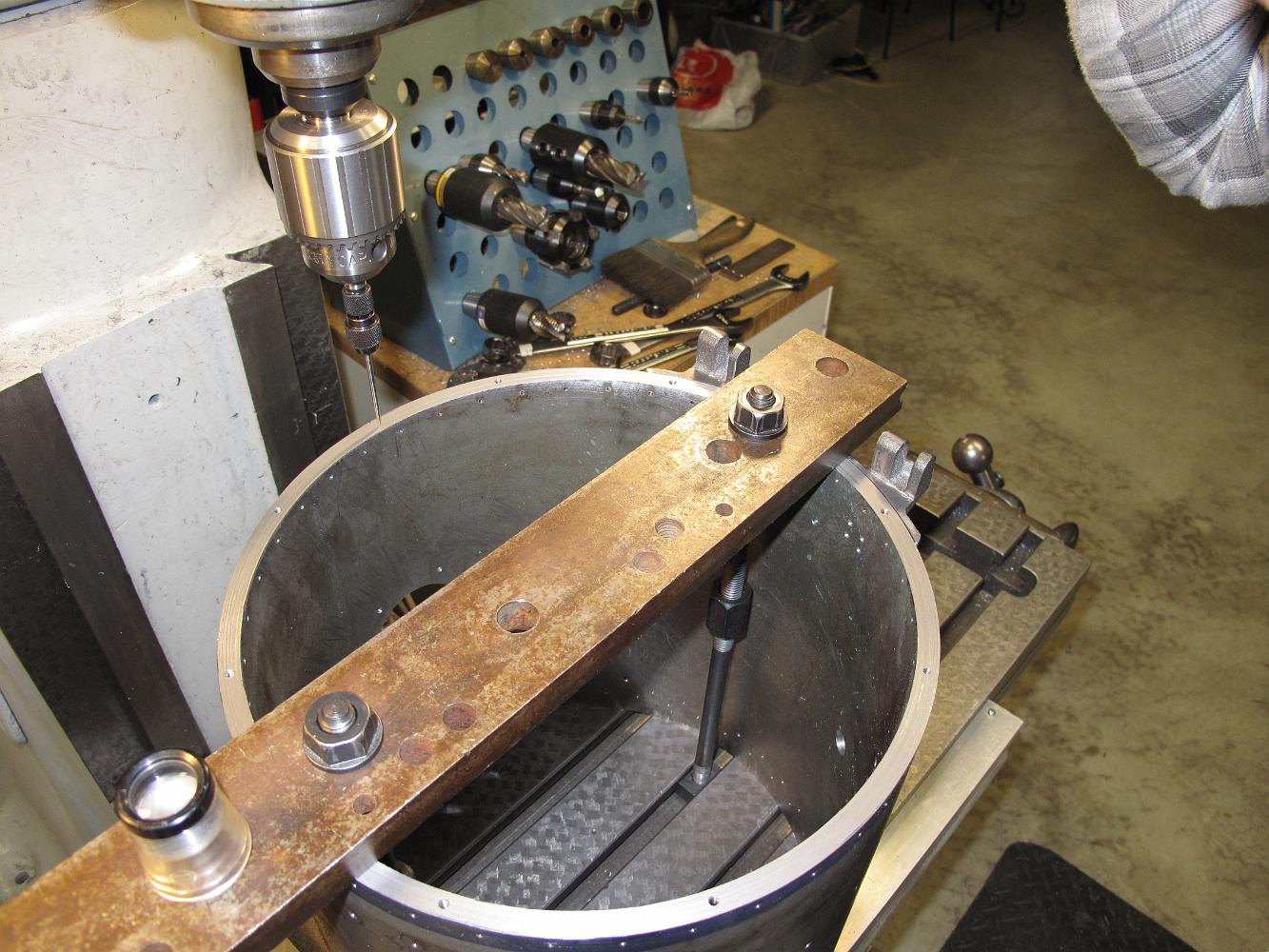
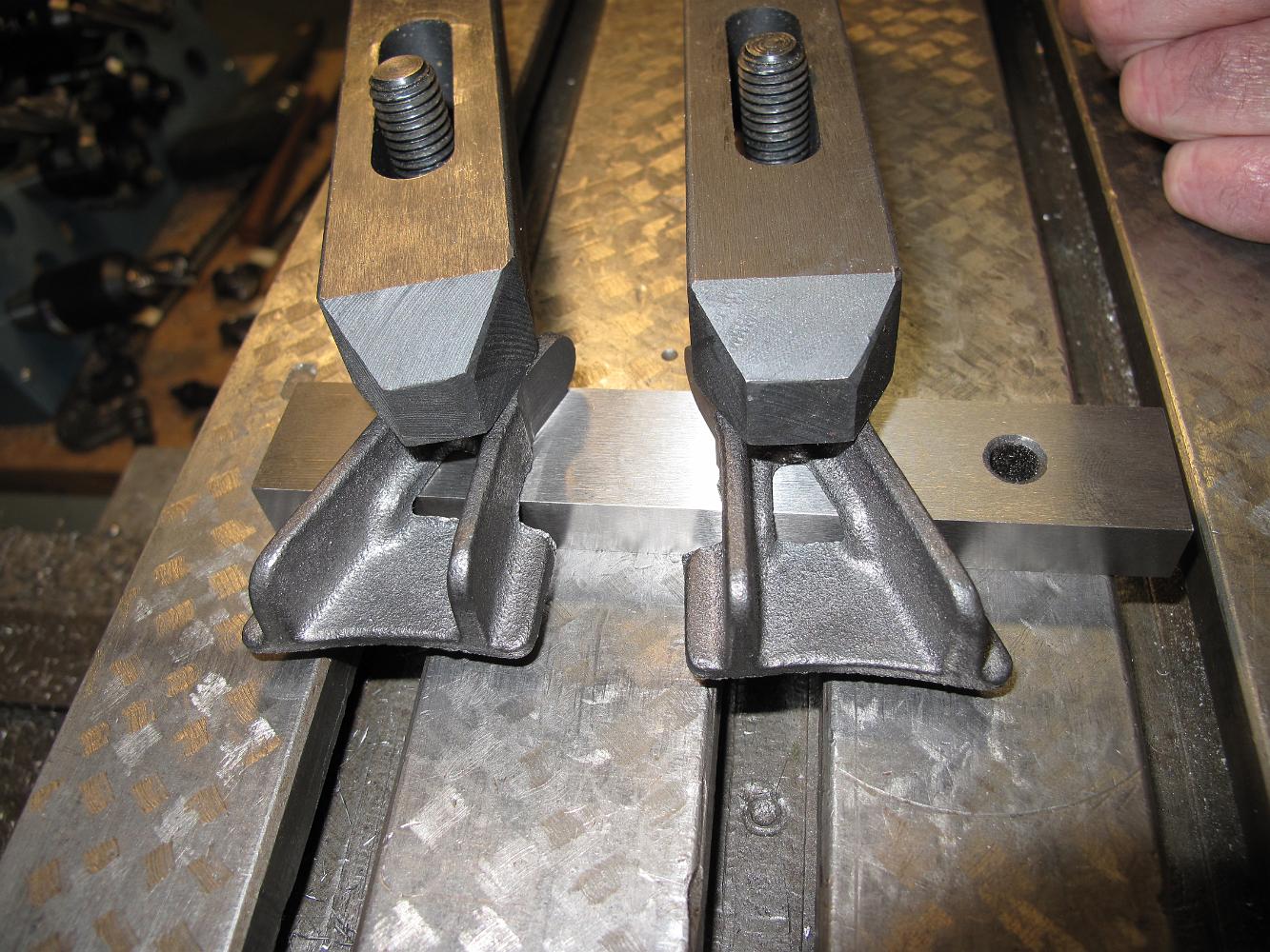
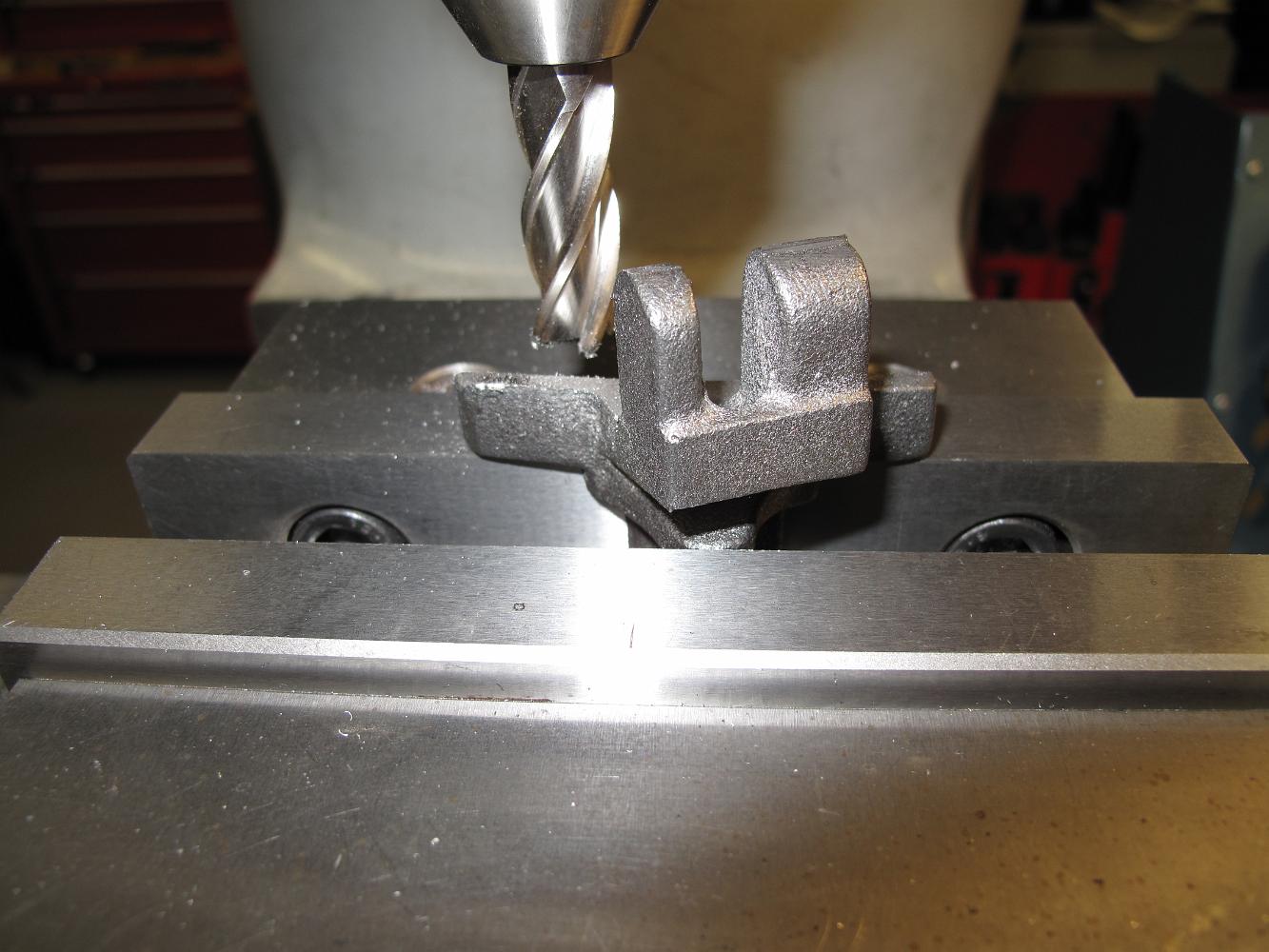
5-Jan-2011 Using the edge finder to pick up the edge of the foot so we can drill the two mounting holes. The stop rod is set since we have a second identical…
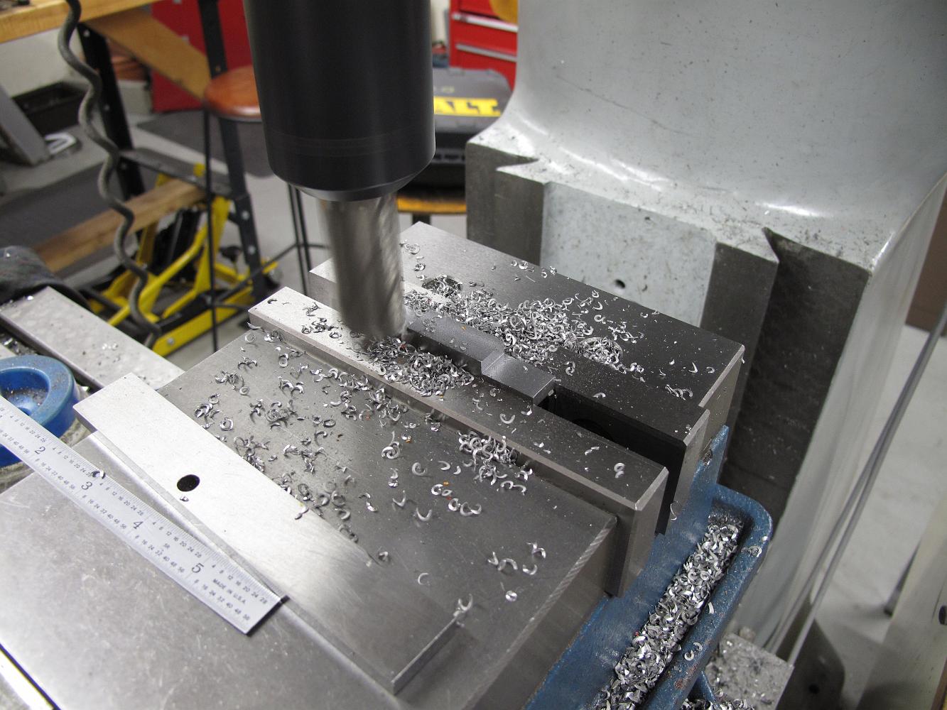
Efficient operations here: Drill, unclamp, turn part, push against stop rod, clamp, drill & repeat! 8 holes in a jiffy!
8-Dec-2010 The upper brace flanges are square and symmetrical. Bill puts a stop rod in the vise and starts drilling.
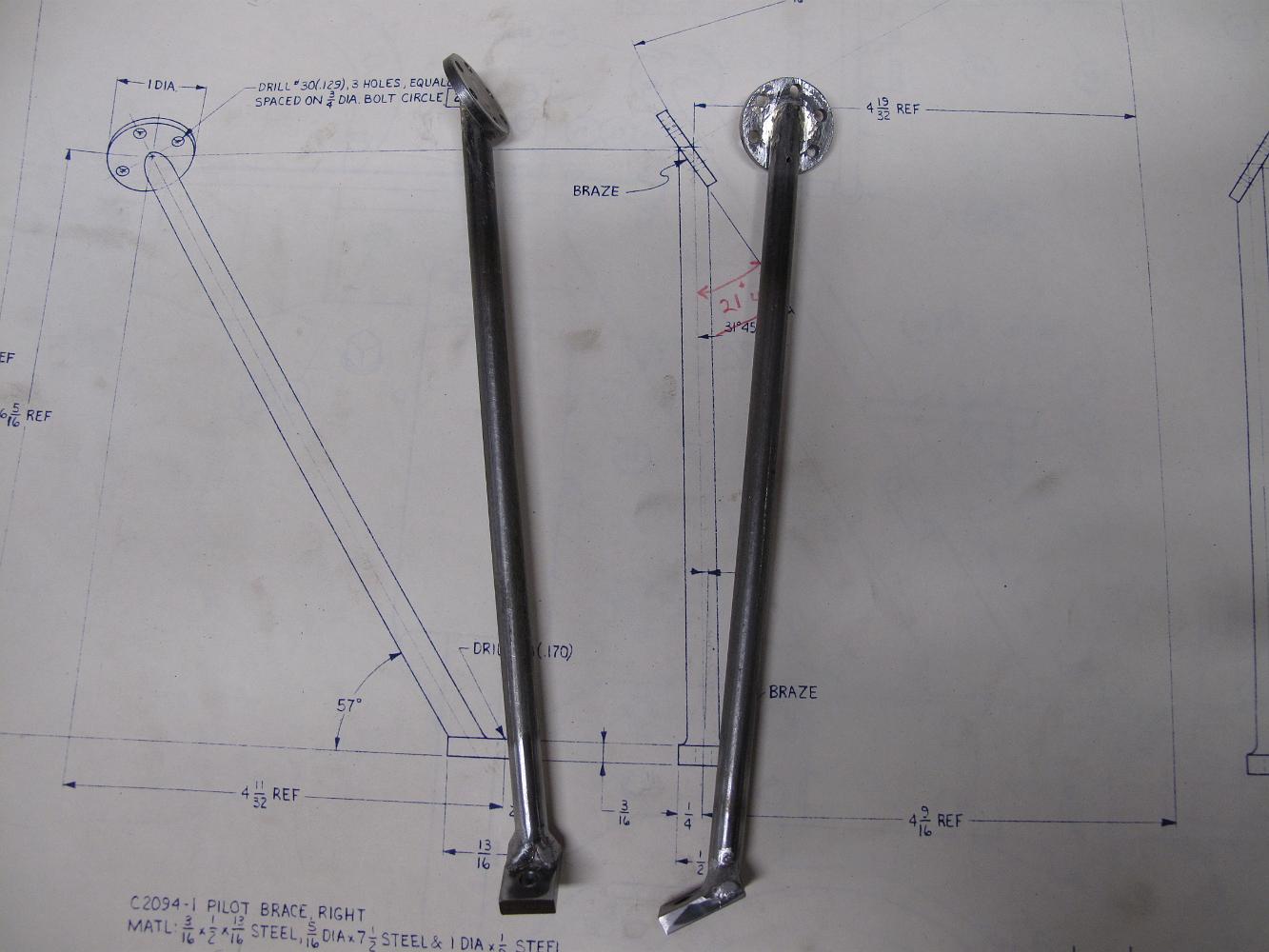
8-Dec-2010 The assembled pilot braces, silver soldered at one end, welded at the other, all blended with a small file and sanding belt!
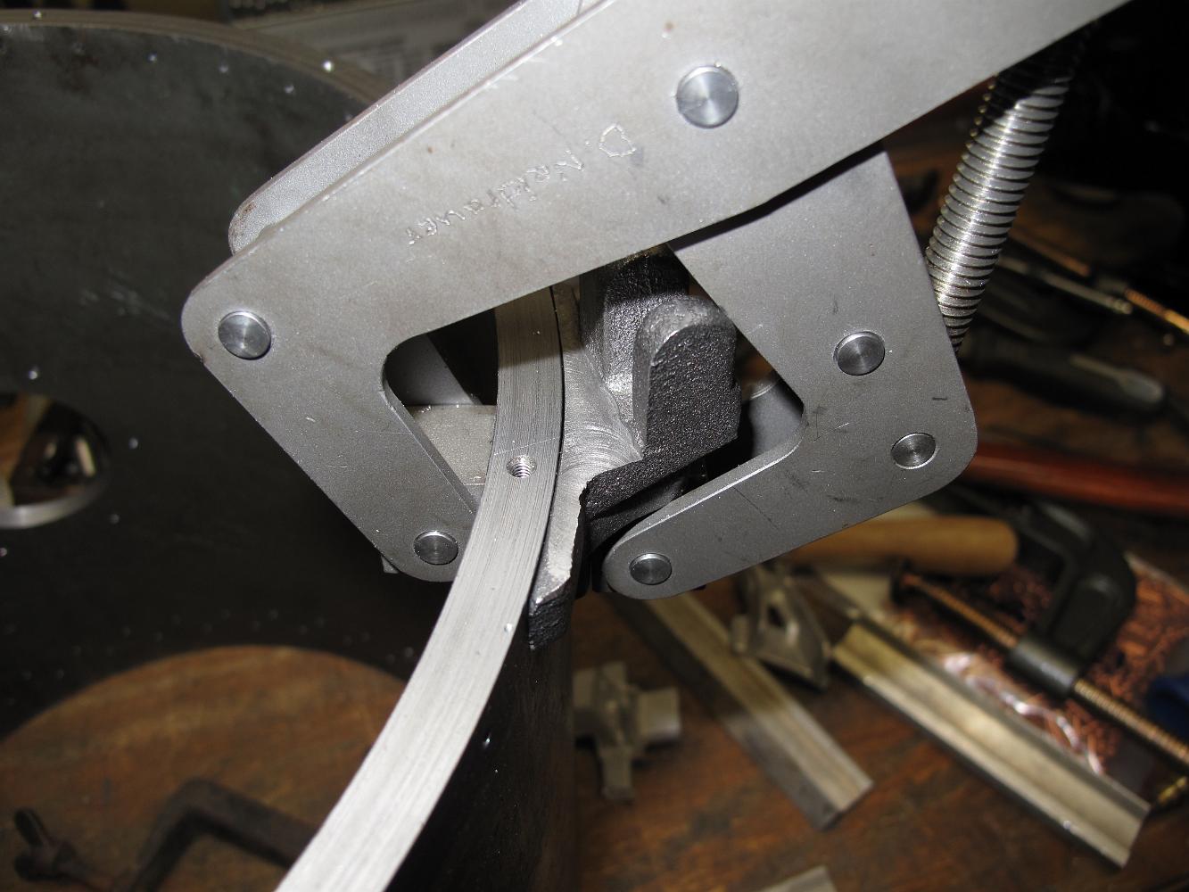
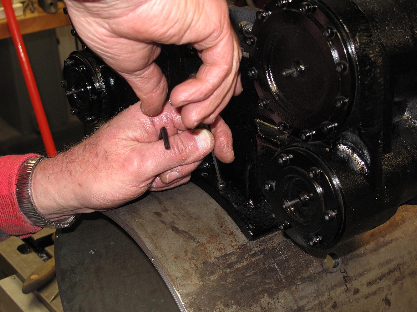
8-Dec-2010 I don't know how anyone could weld or solder this assembly up on the workbench. I ended up bolting the foot to the pilot deck and Bill held the rod…
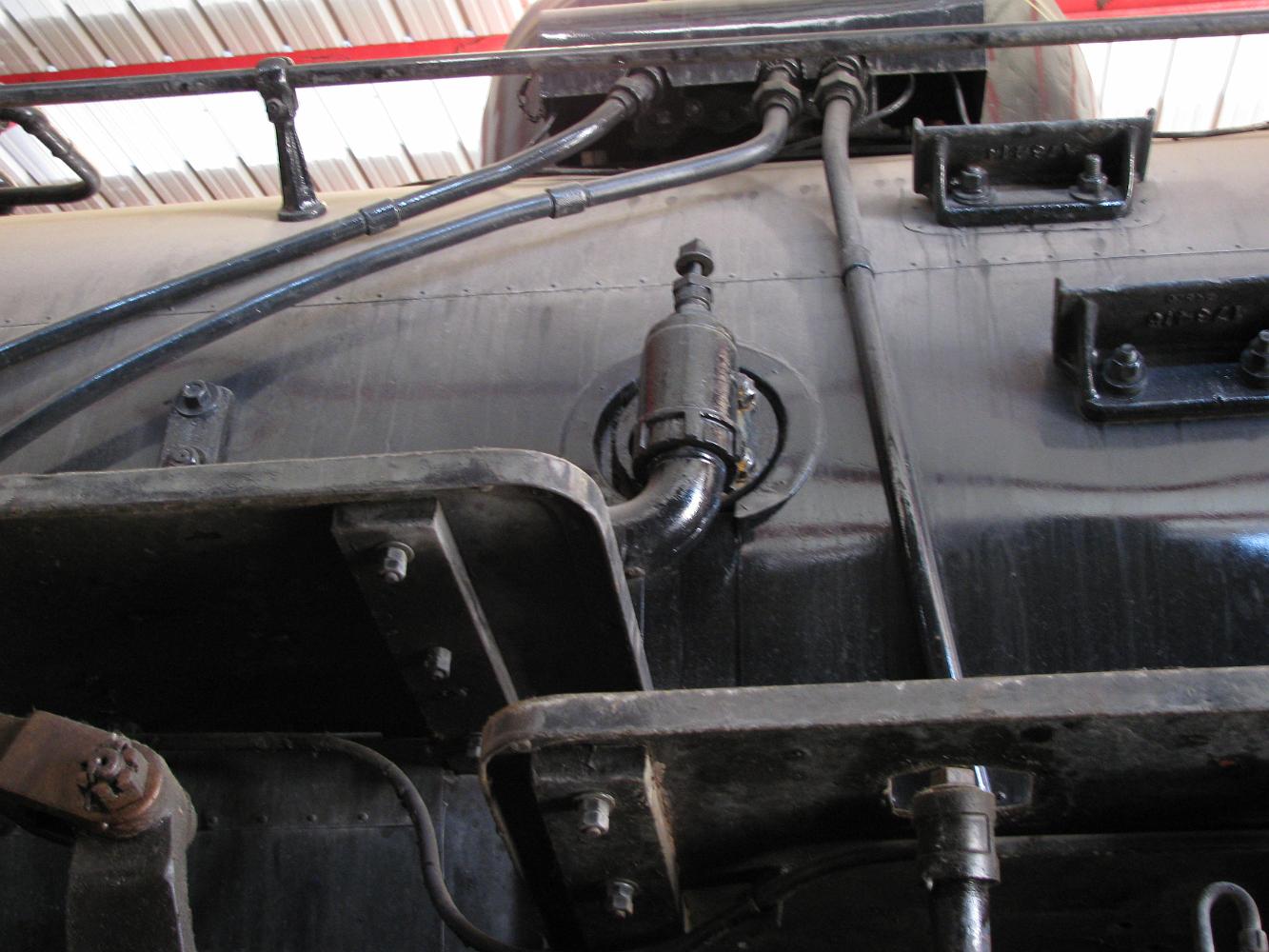
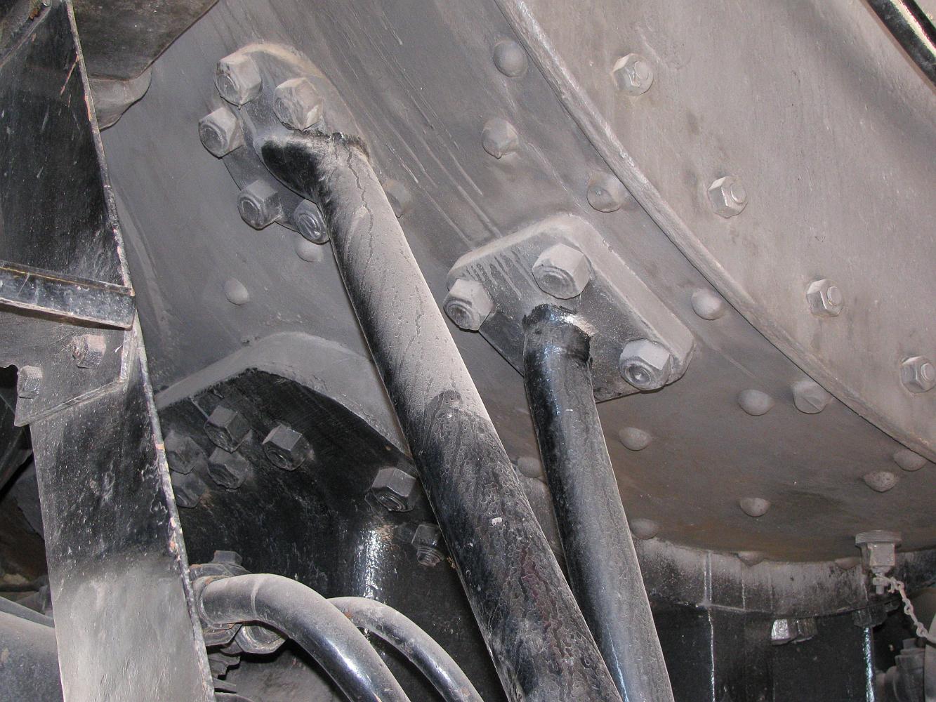
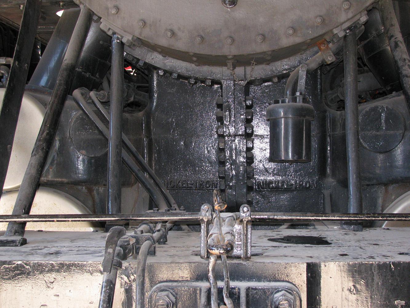
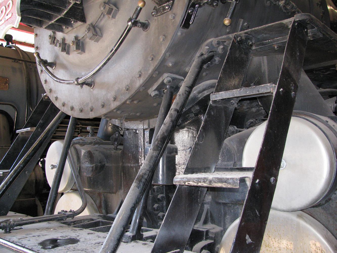
Smokebox stays on the full size Frisco 1522. A nice clear shot of the 5-bolt round flange and 4-bolt square flange. We're guessing the pilot stay rod was forged…
Frame to Pilot connection on the full size Frisco 1522 showing how the vertical stay is attached to the frame. This is important since the USRA prints only have…
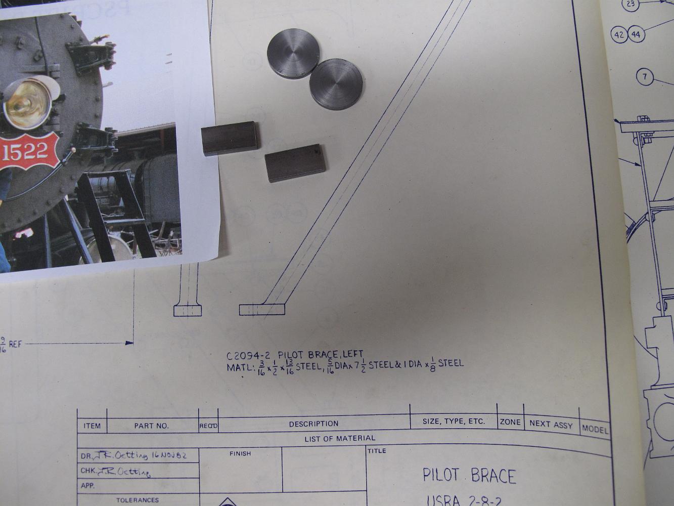
Bill went to the National Museum of Transportation in Saint Louis, MO and took a few pictures of the full sized Frisco 1522 and the pilot stays used. There is a…
Machining the end of the brace flat. We used a machinist protractor to match the angle best we could.
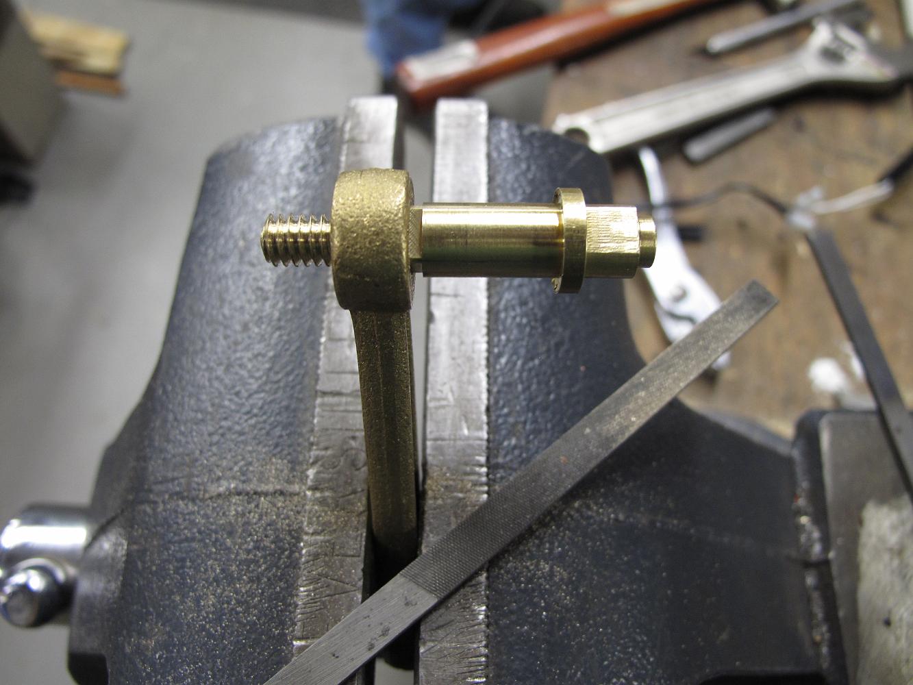
14-July-10 The parts of the 1/4-turn fast -opening gate valve on the bench. There was waaay too much slop in the valve stem - gate connection (center part), so…
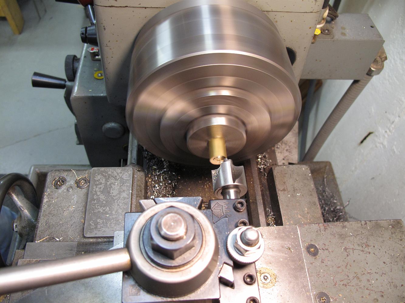
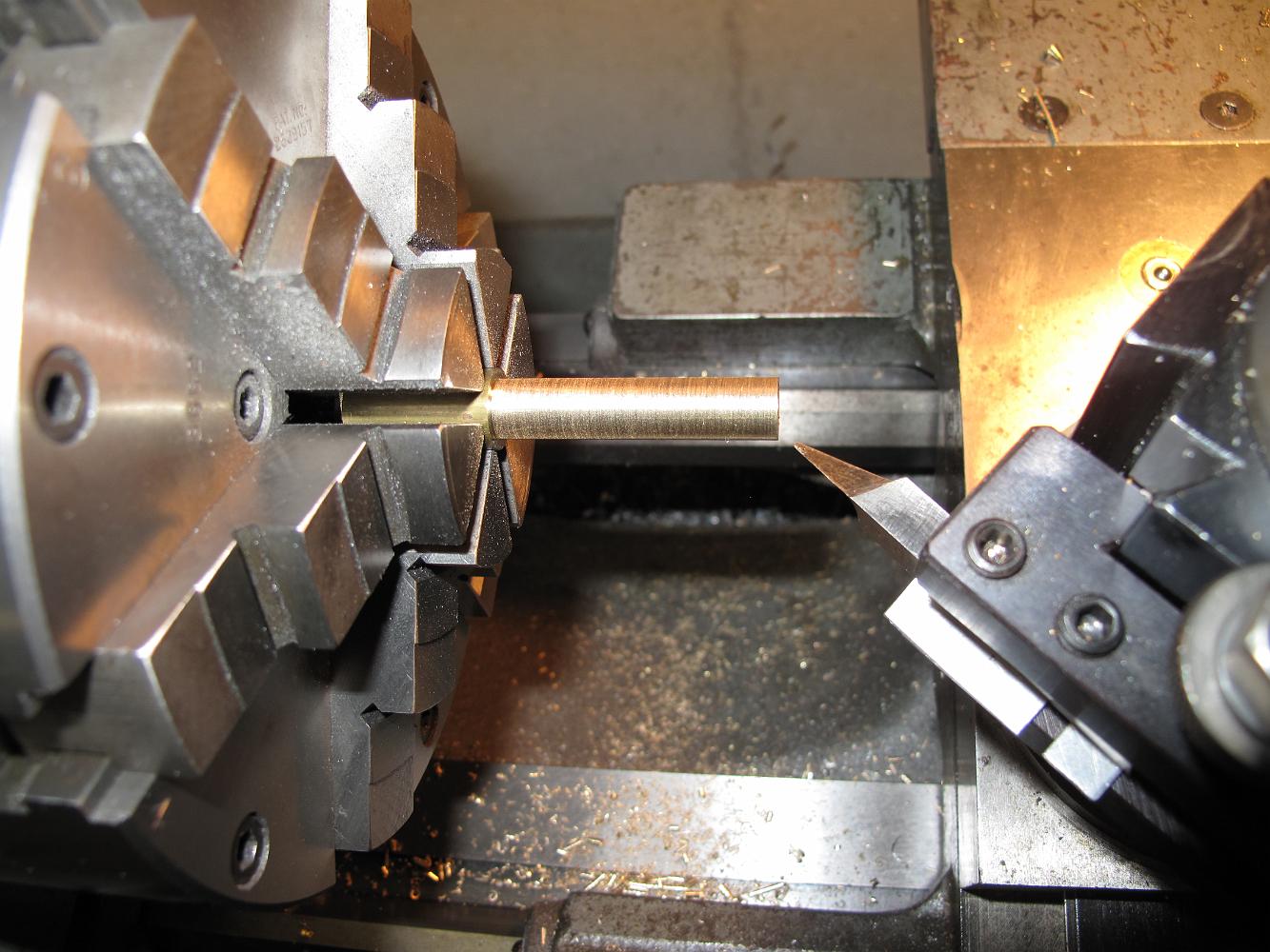
Turning a piece of brass with a specially ground tool to make the new valve stem. The special tool is needed to put an inside cup face on a shoulder, which…
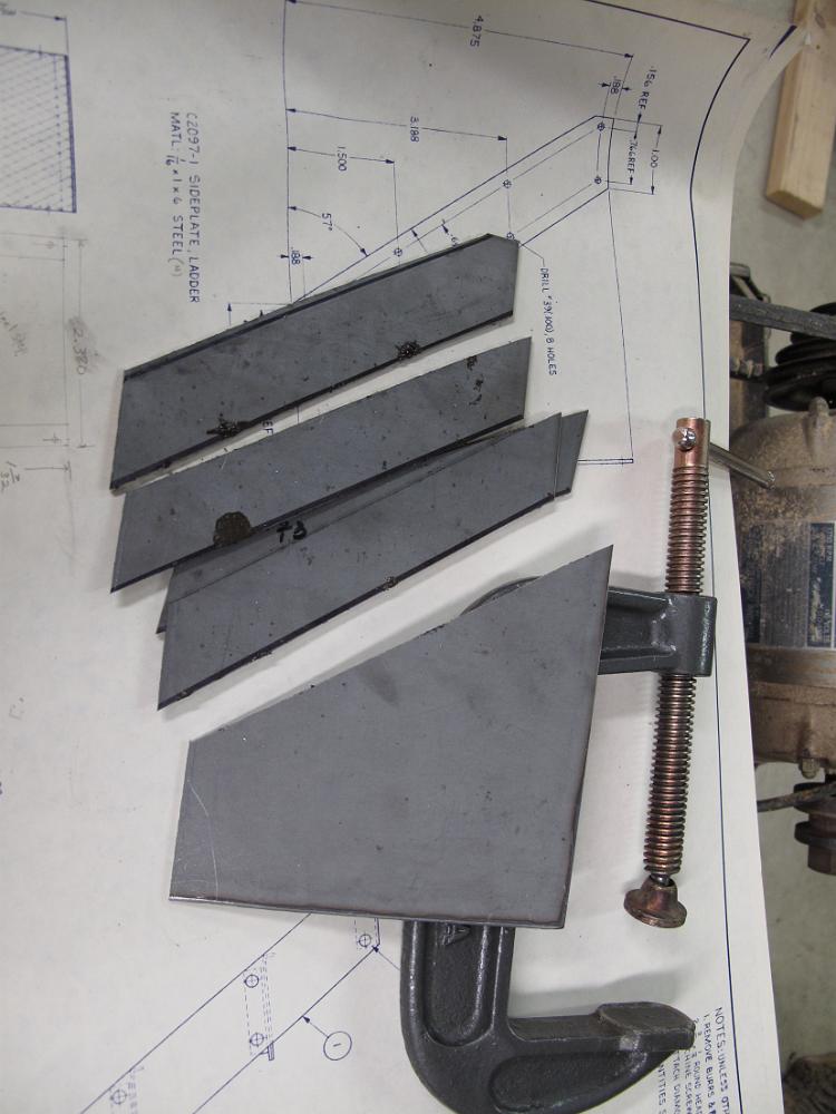
The first 45 degree bend is completed for three pieces and I sneak a picture while the fourth is bent. After this a 90 degree bend is put on the ends with the…
With the holes drilled in the bracket, the old box brake is put to service for two bends each bracket has on it. He is actually bending the 3/16" cold rolled…
10-June-09 We start on the smokebox running board brackets. Bill has machined four pieces of stock to size and has stop set up for in the vice to make the…
The smokebox section is the start of several sections with a lot of little things to do. Here Bill is drilling the handrail for the headlight bracket. I still…
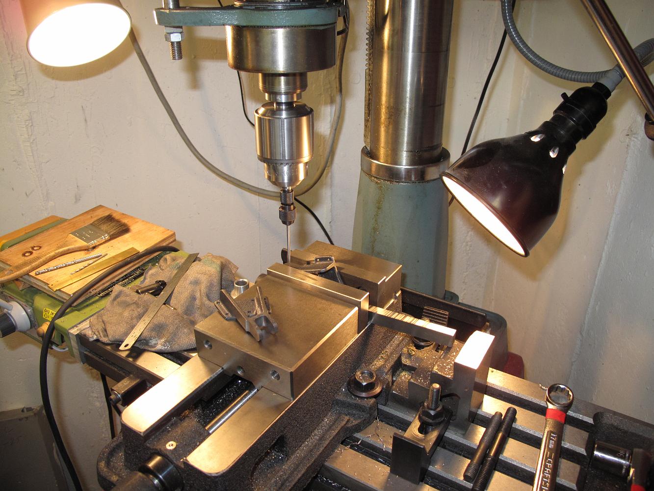
Drilling the holes in the sheet metal really calls for a drill press, not a mill. Since my 1930's era Barnes 14" drill press is still waiting upstairs in the…
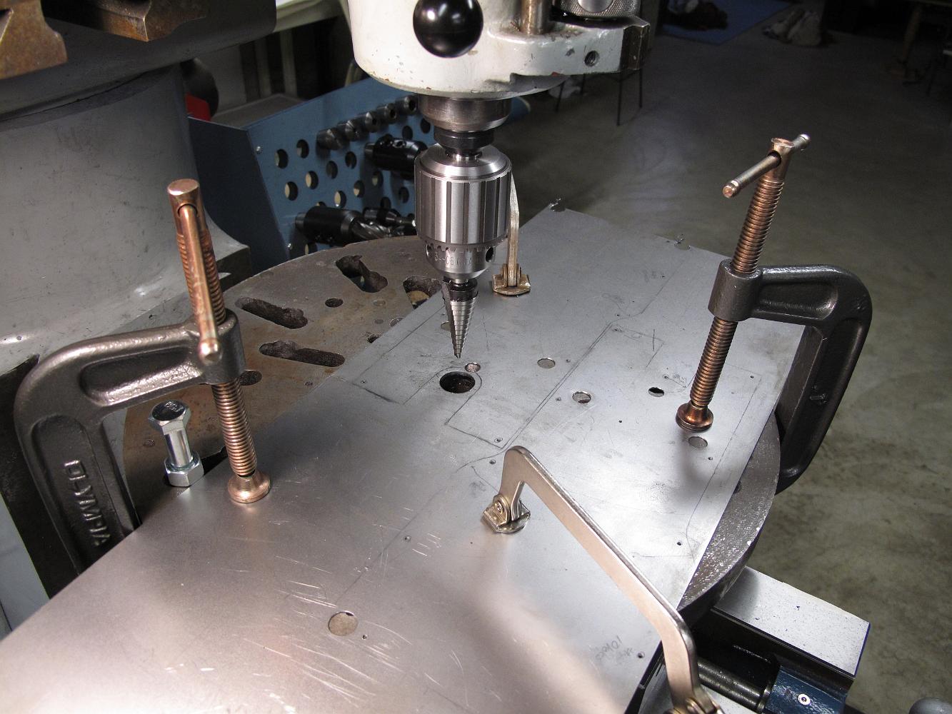
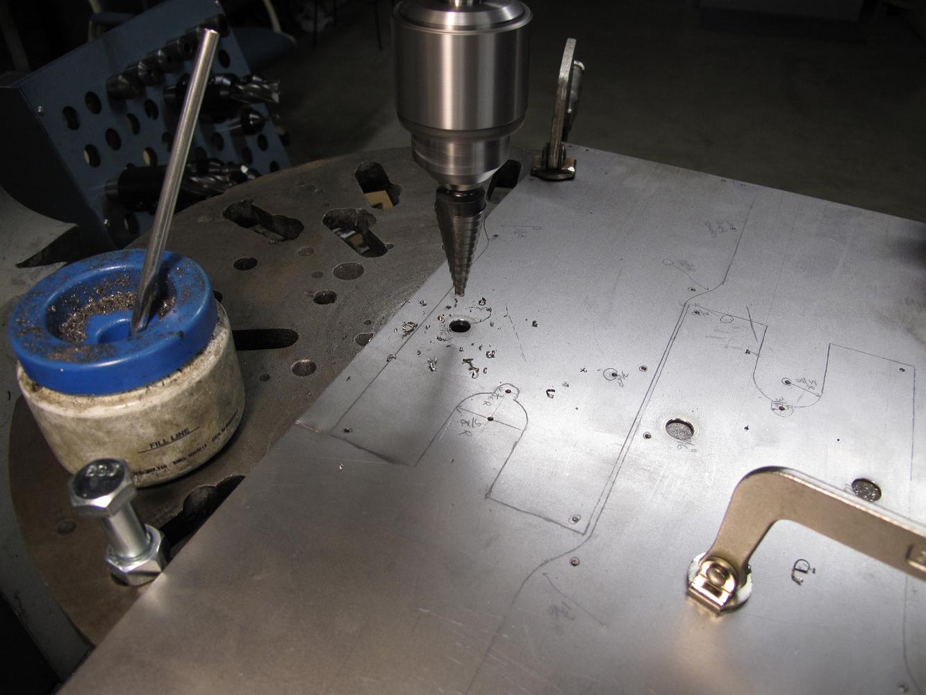
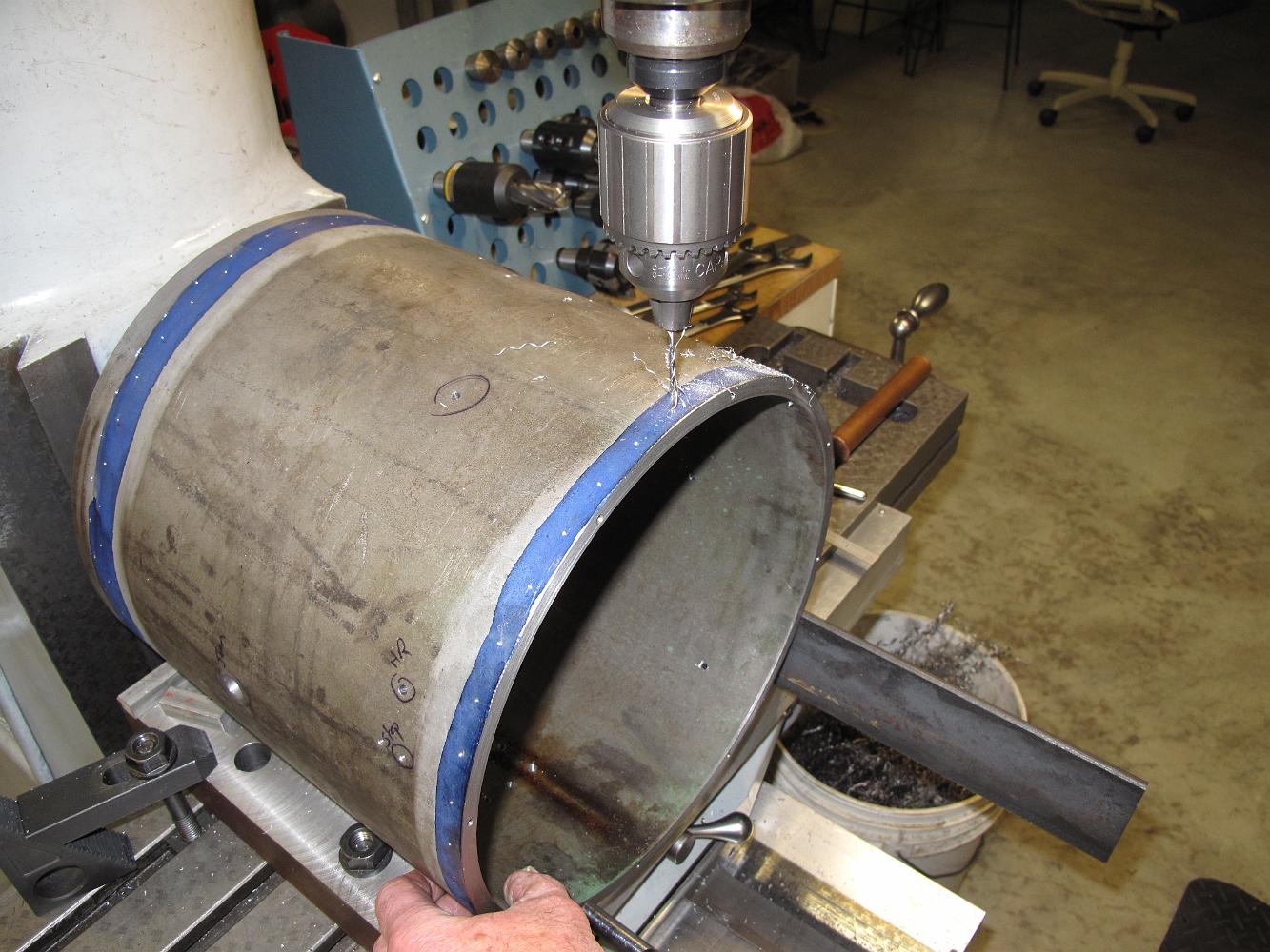
3-June-09 Using a step drill bit to cut the holes in the cylinder jacketing. Each hole was piloted before using the drill, the advantage of this style is it…
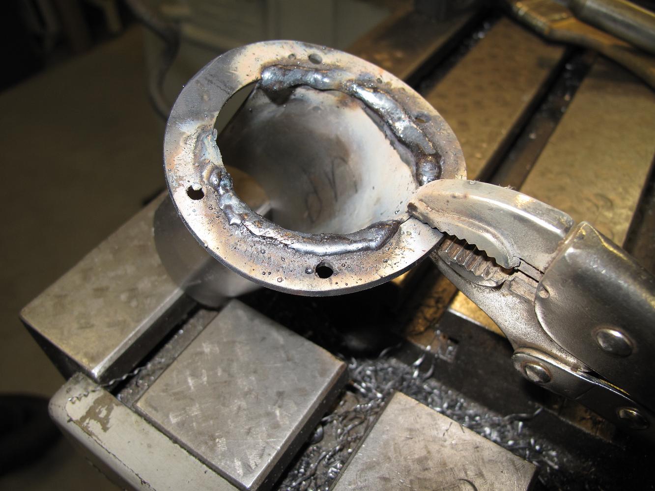
With the flange hole to the proper size, it is outside for some welding. Using a temporary table setup, and dodging the raindrops (not a good mix with an AC…
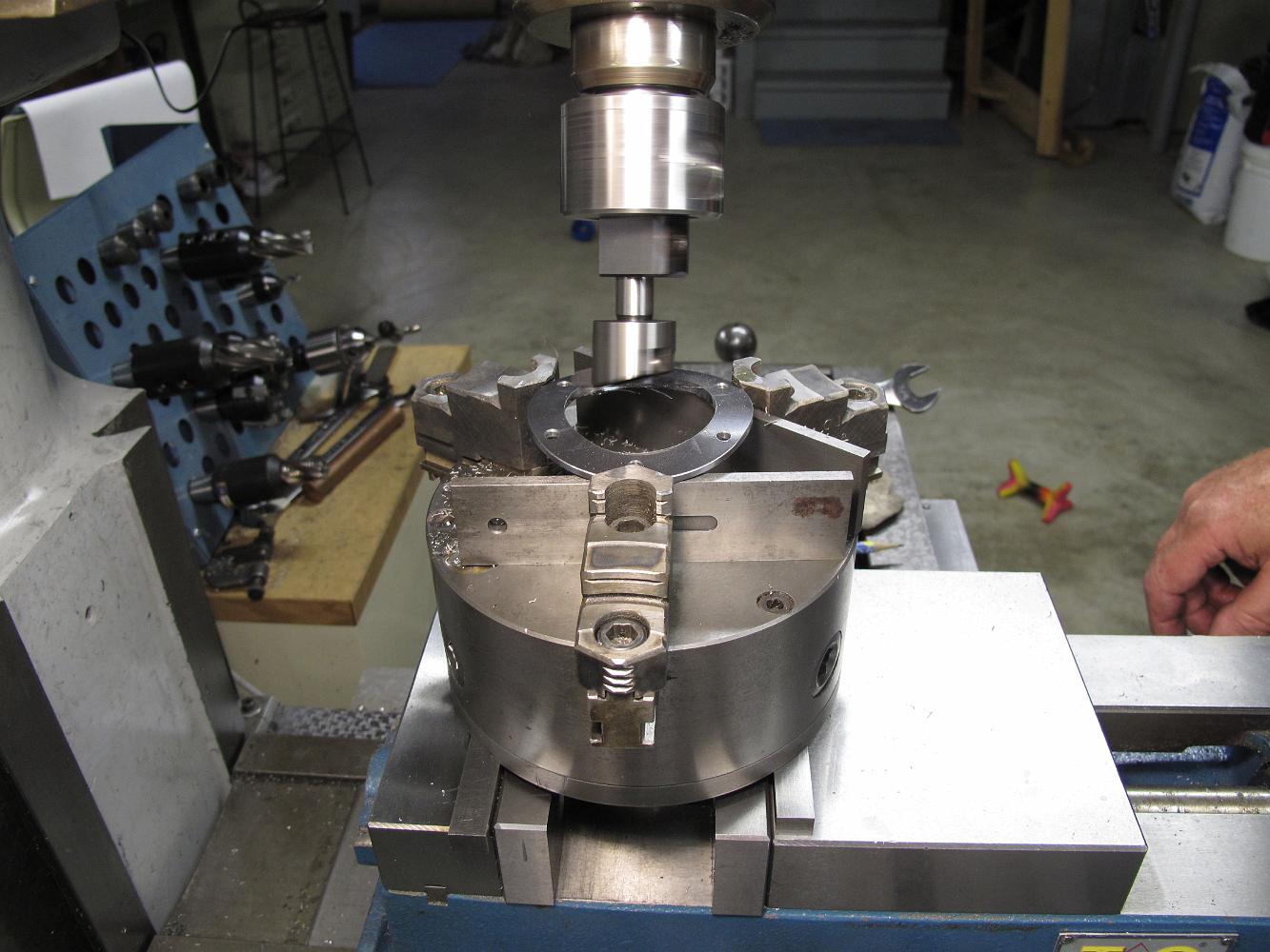
We center the boring head as best we can and bore the angled hole in the curved flange. We advance the cutter after each pass until it just barely reaches 2"…
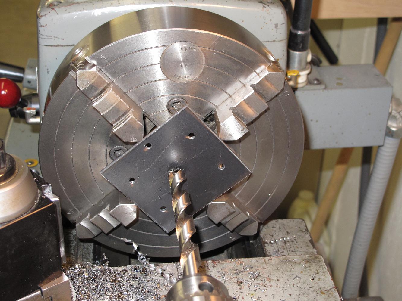
The chuck is clamped in the vice. We want the middle of the flange (left-right when the finished part is mounted on the smokebox) to be in line with the front…
We decide to use the 3-jaw chuck. It has tall enough jaws to allow for the 1" clearance the boring head will need for the 23 degree angle tilt. We will clamp…
27-May-09 After rolling the shroud flange the 2" hole was not 2" anymore --the hole is oval shaped and it needs to be cut at an angle. After considering several…
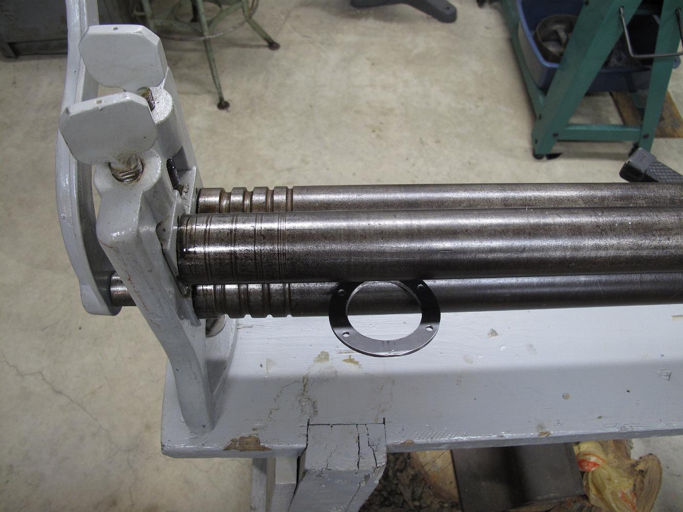
We used my antique roller to roll the casing and casing flanges. These are 2" rollers so we could not roll the outside casing too small!
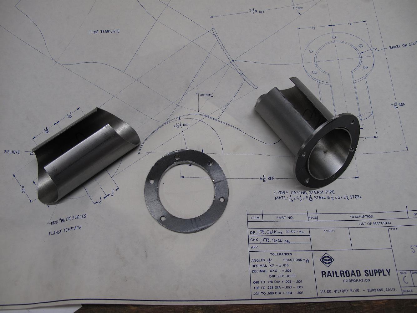
Cutting the outside of the steam pipe casing flange make chips fly all over our faces (ouch! hot chips), so we clamp a piece of plastic in front to deflect…
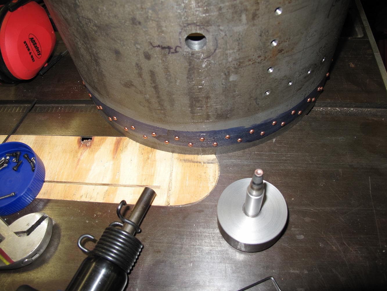
120 Rivets later, the smokebox shell has all the decorative rivets in place. This was actually fun to do!
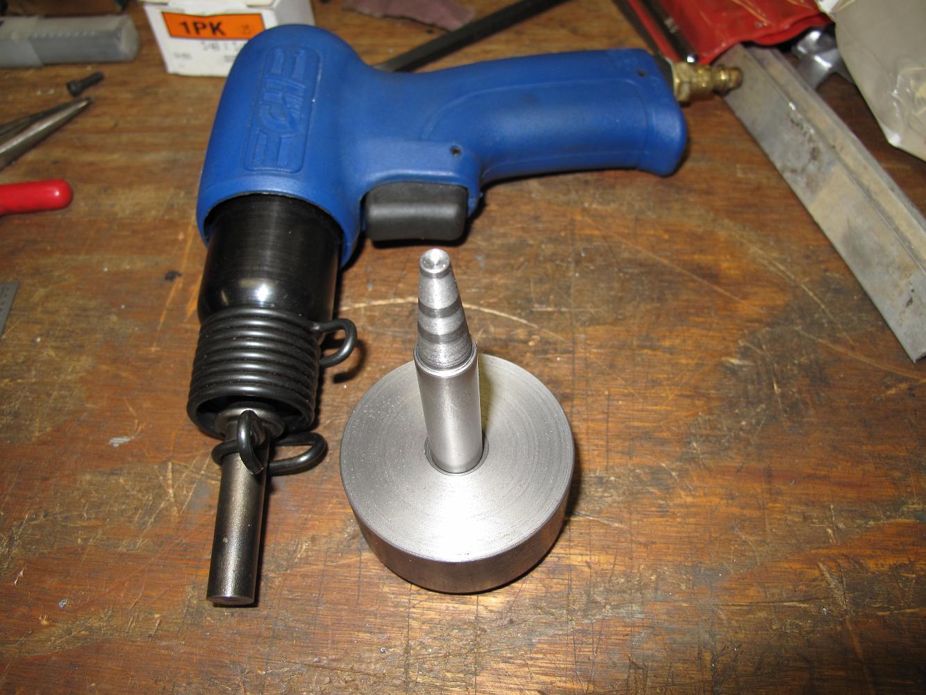
The finished buck and air hammer rivet set. I would recommend you get a 'palm nailer' instead of the pistol style hammer. Holding the gun is hard on the wrist…
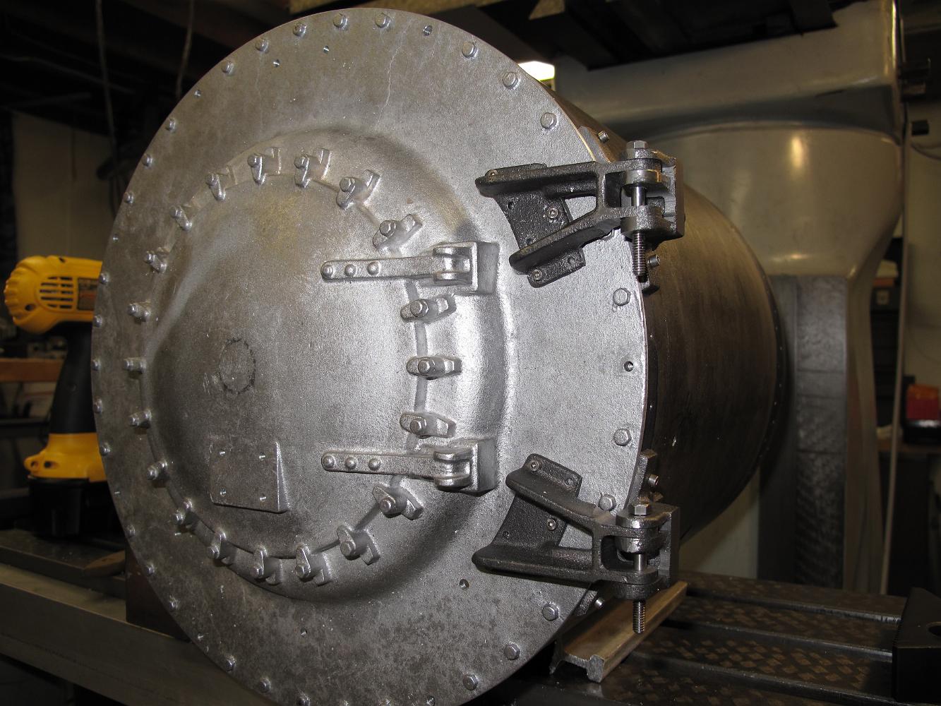
With temporary bolts holding the hinges to the front cover and the shell, we test the hinges -- And the work smoothly without any binding or excessive slop!…
The convenience of a second machine in the shop. Without disturbing the setup in the big mill, we use the mill-drill to drill the front cover hinges, relying on…
6-May-09 With the hinge pin holes drilled in the shell hinges, we set the front cover hinges in place and using a transfer punch mark where they should be…
There was no way to reach the bottom hinge - not enough quill travel and too many things in the way. We had to turn the shell over and cut from the 'underneath'…
4-Apr-09 We also decide that the little end mill we used to cut the slot in the hinges did not cut deep enough. We rebolt the shell onto the table and using a…
4-Apr-09 Looking at the smokebox front print, we realized we did not turn it to the correct thickness and put the relief step in the back. So back onto the big…
Using a resharpened carbide bit (the only way I can afford carbide cutters are by getting used ones) we oh so gently cut the back of the hinges. After a single…
We decided to lower the front hinges to make it line up better with our thicker front and the shell hinges. Here they are clamped to the table.
1-Apr-09 We tried to use the regular drill chuck in the mill, but with the long drill bit and the table all the way to the bottom, we couldn't make it work. We…
Using the milled surfaces for reference, we bolt the shell to the table and align it to vertical using the combination square. It is a pain clamping the shell…
The 1/8" carbide mill is the smallest one I can find in the drawer. It's a resharpened bit but still does the job.
Using a larger ball end mill, we finish the lower hinge support. We also skim the outside of the hinge to get a vertical reference surface.
1-Apr-09 With the shell hinges temporarily bolted on and the smokebox shell held down on the table vertically, we use a carbide ball end mill to cut the bearing…
We figured the only way we could hold the shell hinge brackets was to rivet them to the shell then mill the slots, insuring parallelism to each other. Here we…
The supplier now provides these brackets in aluminum only, due to the casehardened skin these thin sections have. We chewed up a HSS and a TiCN coated drill bit…
Now to drill the rivet holes. We lift the brackets off the table with a parallel and clamp away from where we have to drill.
Using a ball end mill, we clean up and machine the hinge tabs. Since these brackets are cast iron, we use a carbide mill. I think the results look good!
28-Mar-09 The smokebox front hinges are easier to clamp, just line up the straight side with a square to the vice.
Another clamping conundrum, how to hold the bracket to the shell to match drill the shell holes to the bracket.
25-Mar-09 These smokebox shell hinges are just plain hard to hand onto! Here we are making a cleanup cut on the shell bracket portion to fit nicely up to the…
We have not removed the alignment block (left) from the table since drilling the other holes in the shell, so we just roll the shell around to line up the punch…
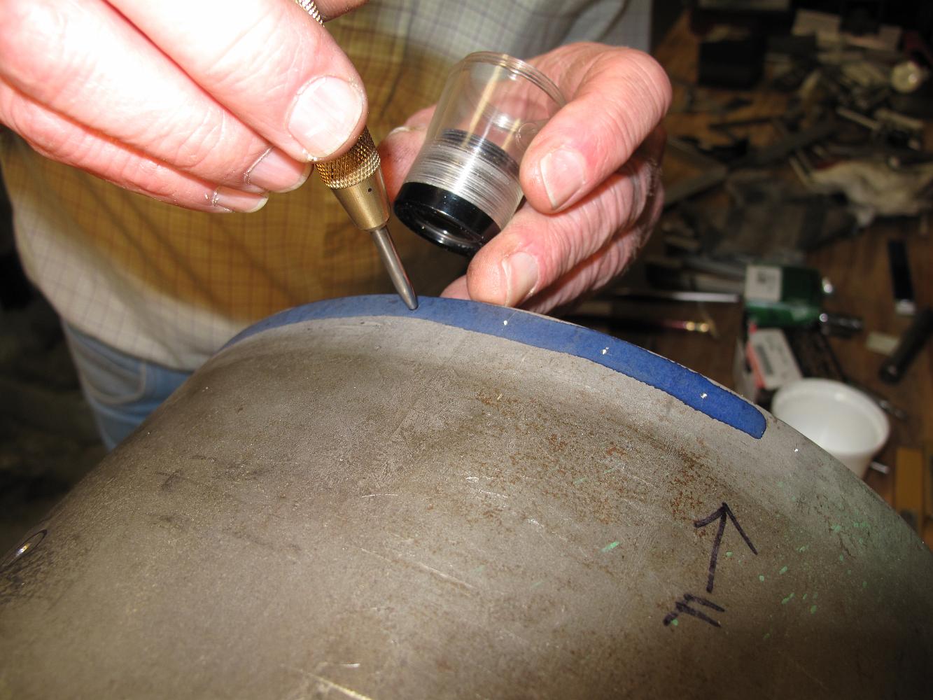
18-Mar-09 Laying out the decorative rivets the old-fashioned way: Layout dye, calipers and a center punch. 4 done, 116 more to go!
Success! With the handrail, headlight and bell holes drilled in it, the cover fits on the shell without needing adjustment.
Running the same bolt circle program with the same dimensions as the smokebox shell, we hope everything lines up during assembly. We find some radial…
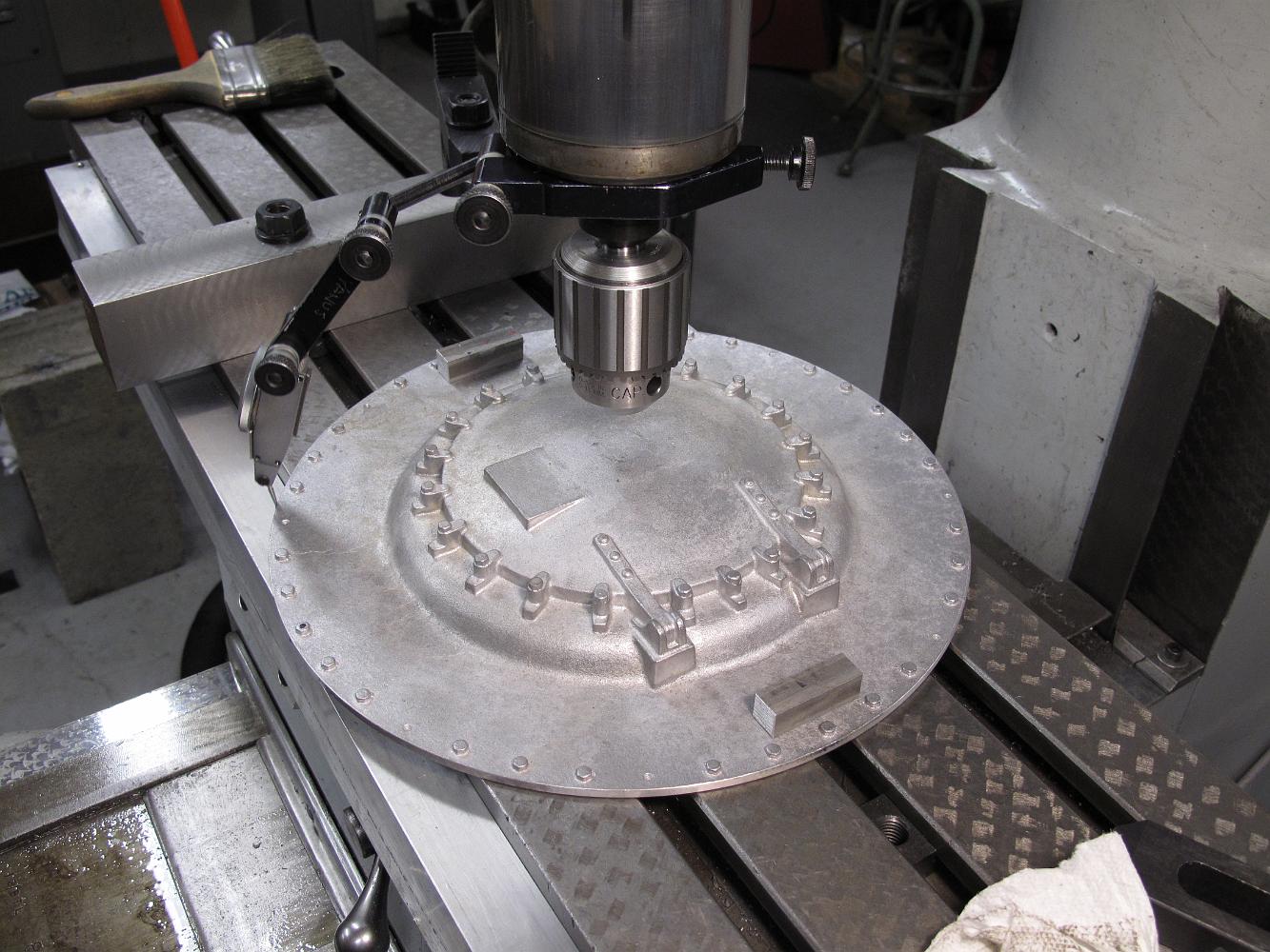
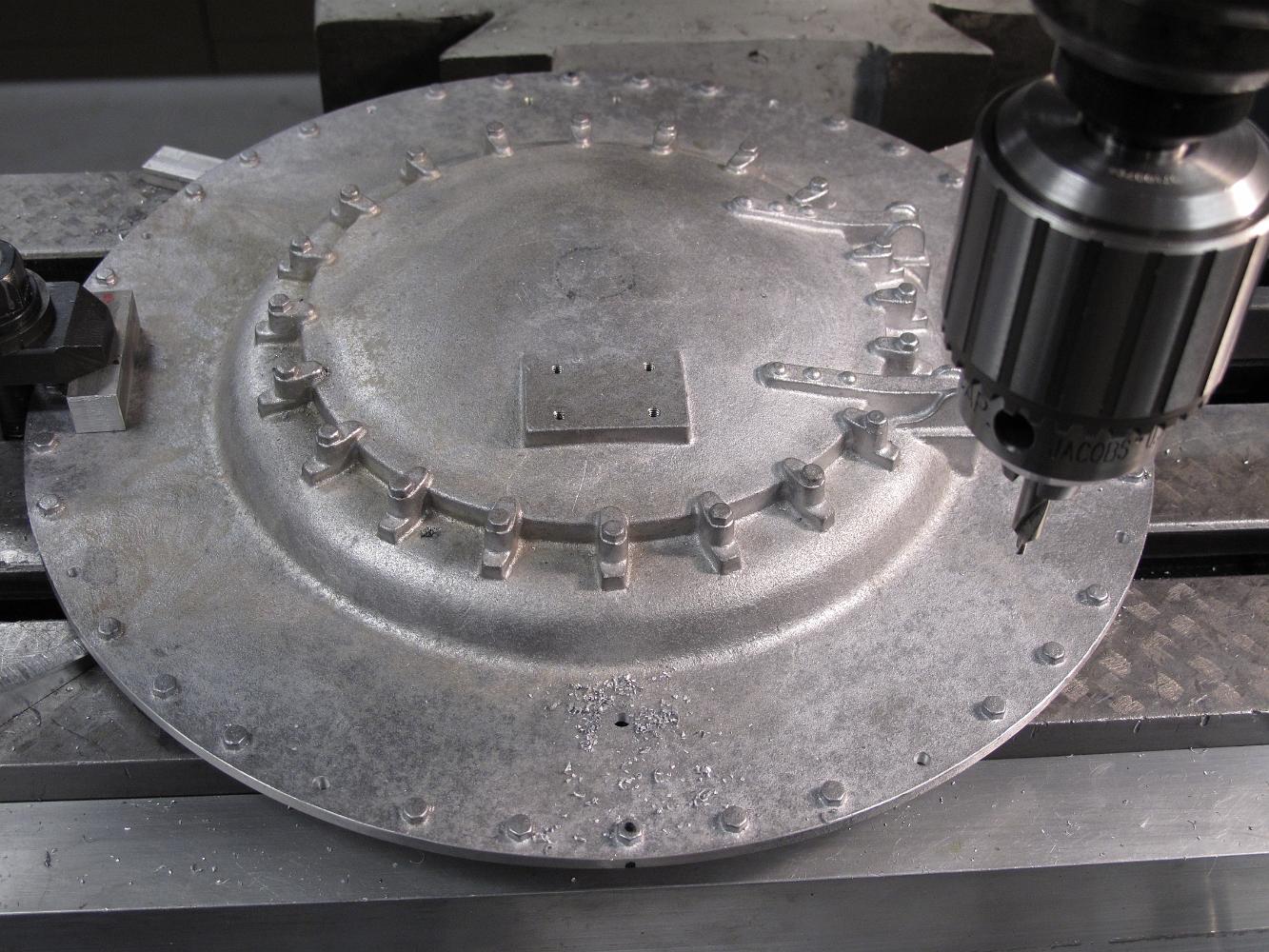
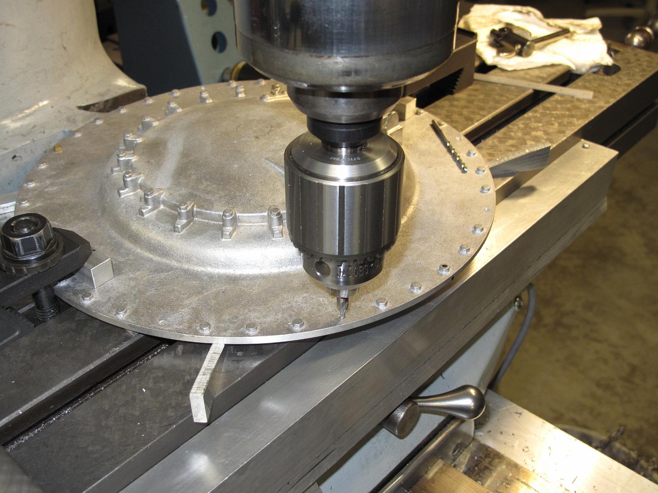
11-Mar-09 With the back of the smokebox cover machined, it is time to drill some holes. Setting the cover on the table, we indicate the outside to center it. We…
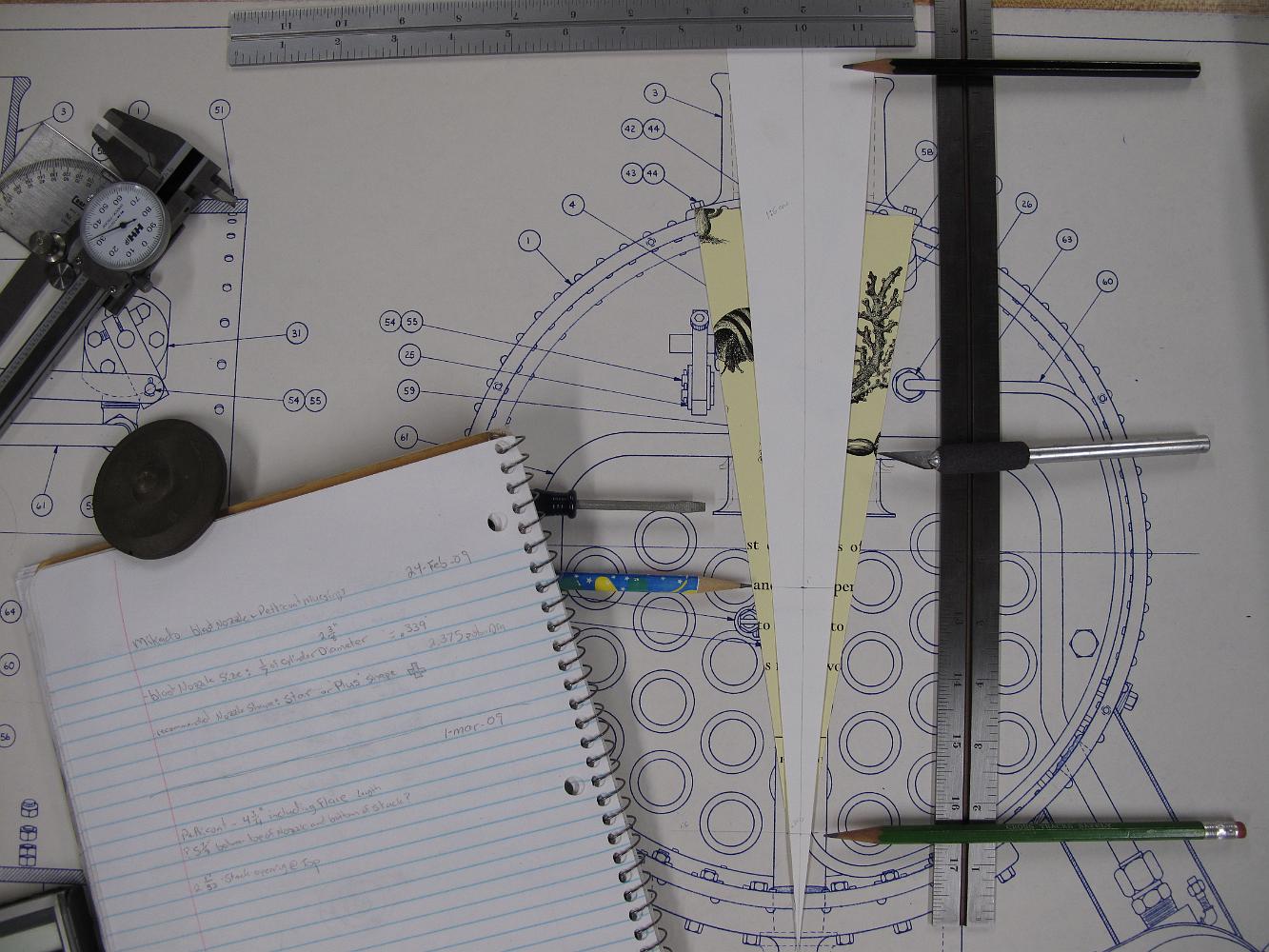
I've been running the numbers for the RRS heavy mike I'm building and finding differences between what is drawn and what I calculate. I'm not trying to…
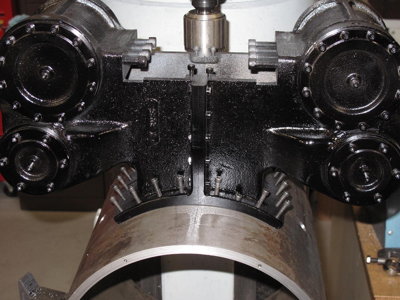
The big question: Do all the bolts holes in the cylinder saddle fit nicely with the drilled and tapped smokebox holes? Answer: YES! we could start all the bolts…
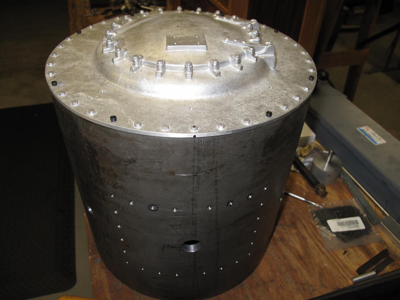
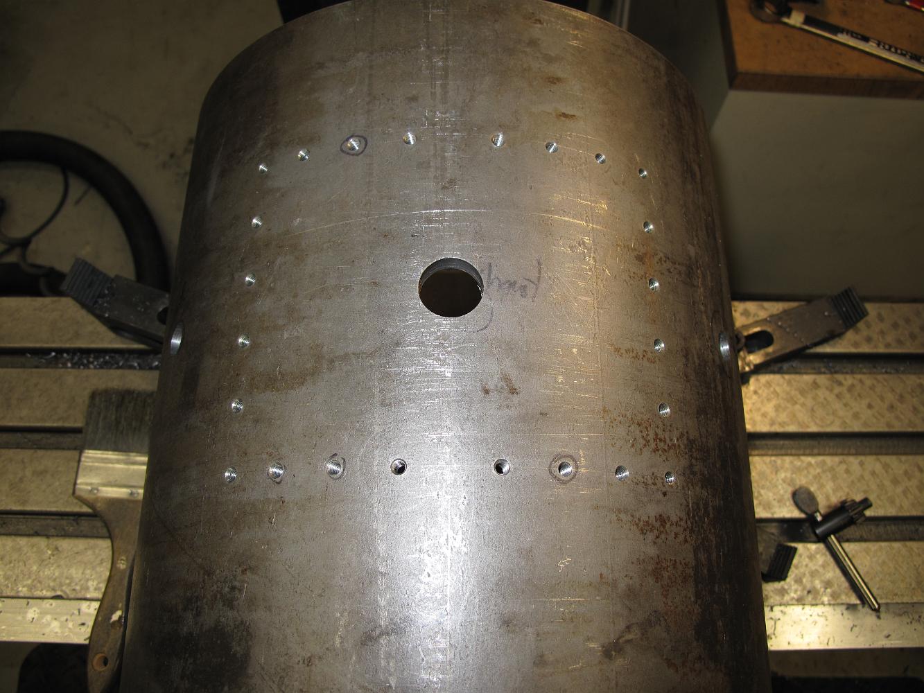
Here's what the smokebox shell looks like after 24 iterations (about 4 hours) of align, drill and tap operations.
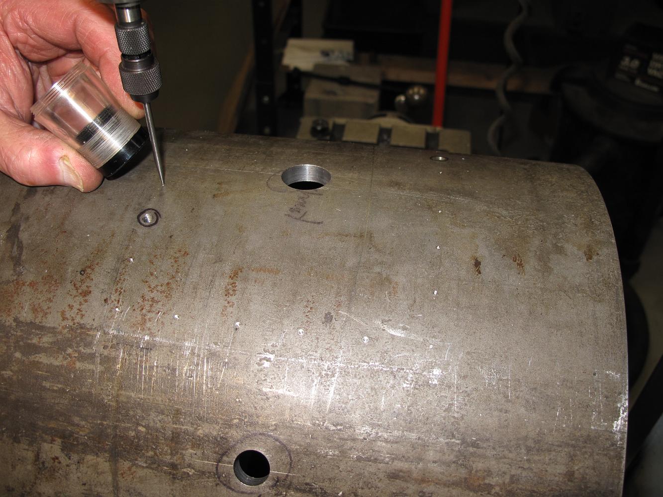
Two holes down, 22 more to go. Here's how it went: Using the pointed wiggler, line the punch point on the shell up under the spindle. After checking the front…
The transfer punch. For these holes under the cylinders, we put a piece of stout steel bar on the punch and the other end on the table. Using a 3 lbs. hammer,…
With two holes drilled and tapped, we put temporary bolts in to hold the cylinders to the shell so we can punch mark the rest of the holes, insuring the…
Using a homemade close fitting transfer punch, we mark two holes in the shell then remove the cylinders. We use the wiggler to line up the head exactly over the…
28-Feb-09 The painted cylinder saddle is brought down from the cold garage and into the shop to match drill it to the smokebox shell. We have scribed a center…
Another Saturday of bad weather means more time in the shop and less out at the track. Good for shop time, bad for getting the track ready for the April start…
We drill just the two holes perpendicular to the smokebox front at first. Our holes are okay, but the cumulative errors between the rotary head, the angle of…
How to lay out the hole pattern? I had a difficult time determining if the print was a straight overhead view (showing the curve of the smokebox) or a plan…
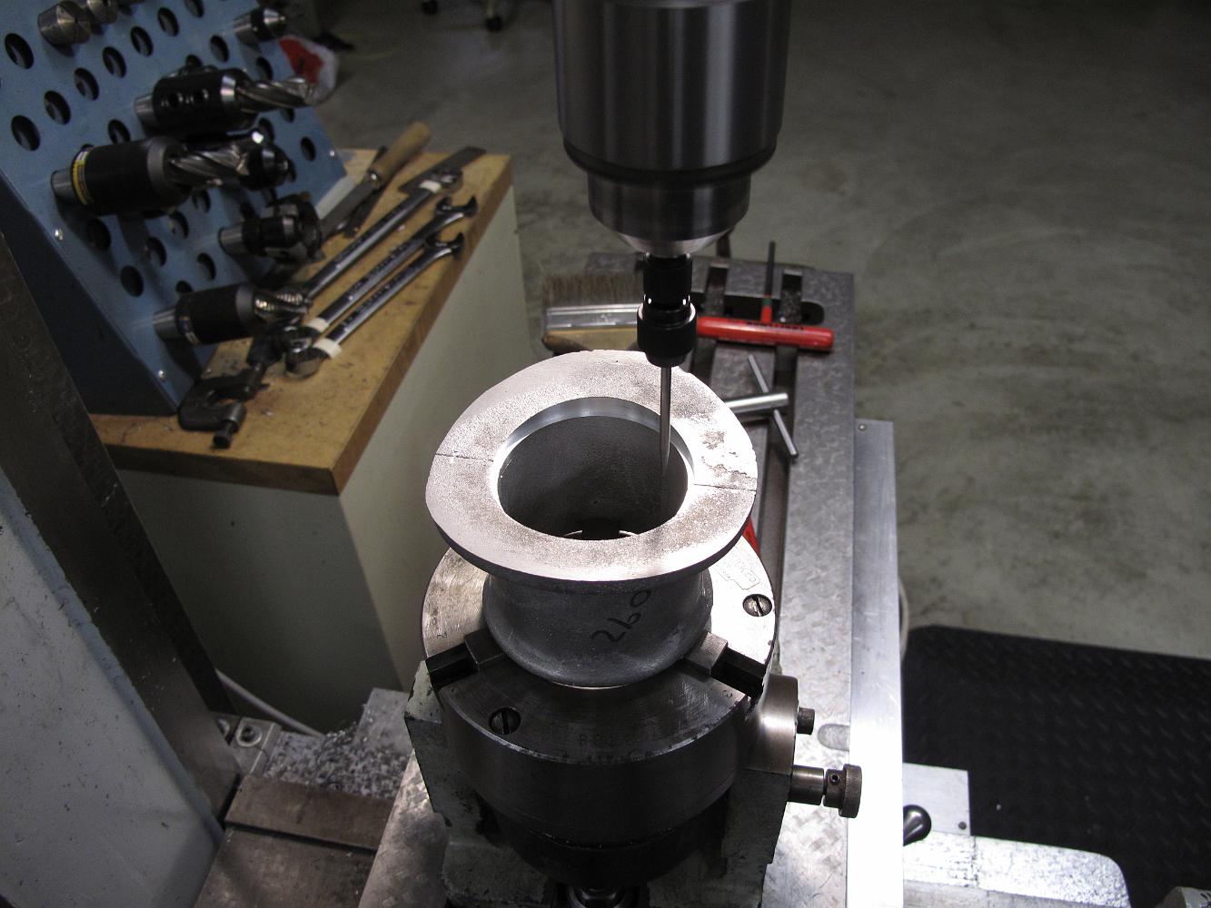
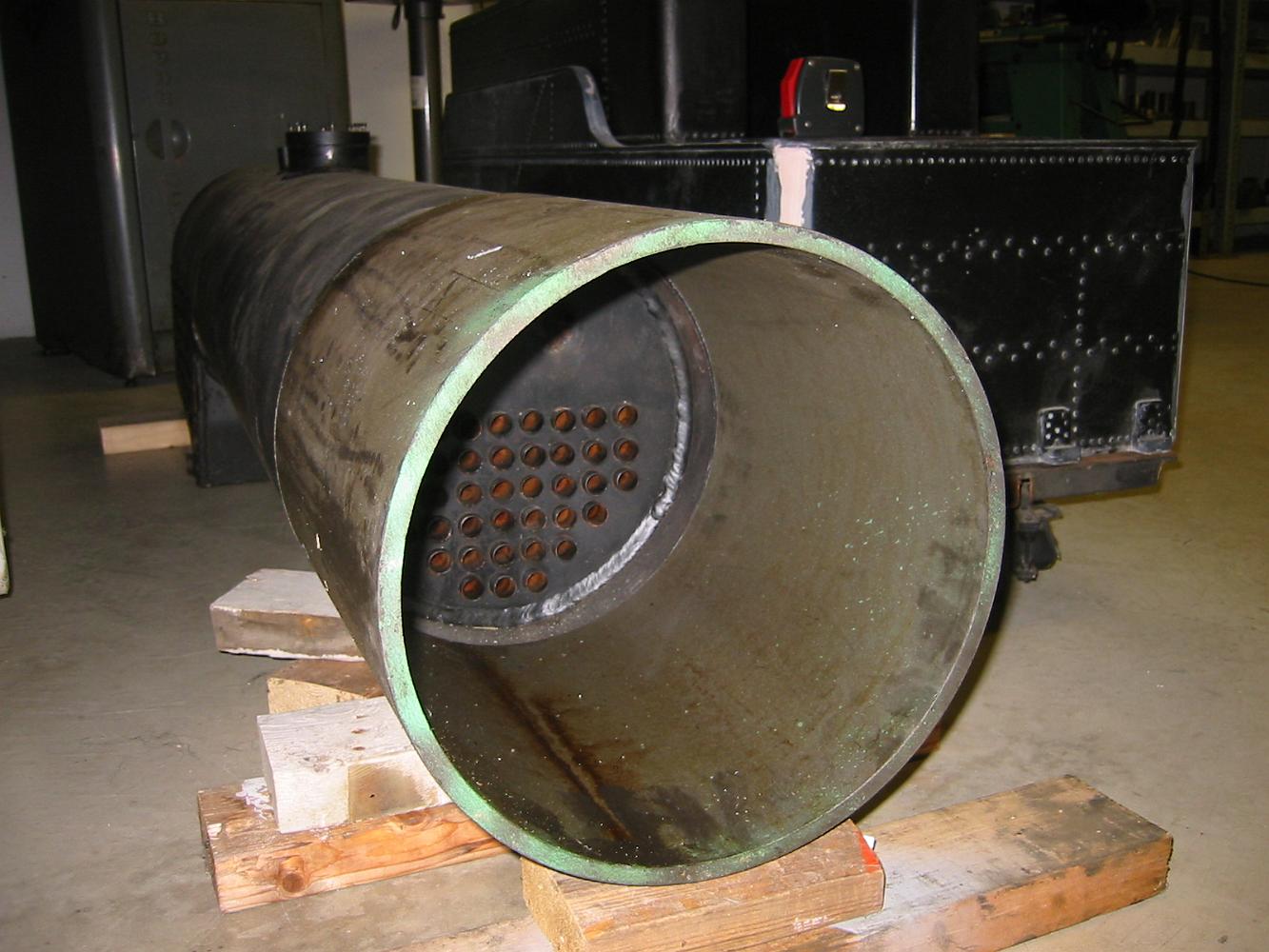
25-Feb-09 With the six jaw holding the end of the smokestack and a boring bar in the tool holder, we turn the recess for the petticoat per the print.
Another good days work! The smokebox shell has the smokestack, blast pipe, steam pipes, handrail and boiler step holes in it.
When we advance to the next larger cutter, we have to look around to find a carbide cutter to put in it. We can run carbide twice a fast and take a heavier cut…
The high speed steel cutters are okay, but slow. We can't take very large cuts - about 0.010 each pass.
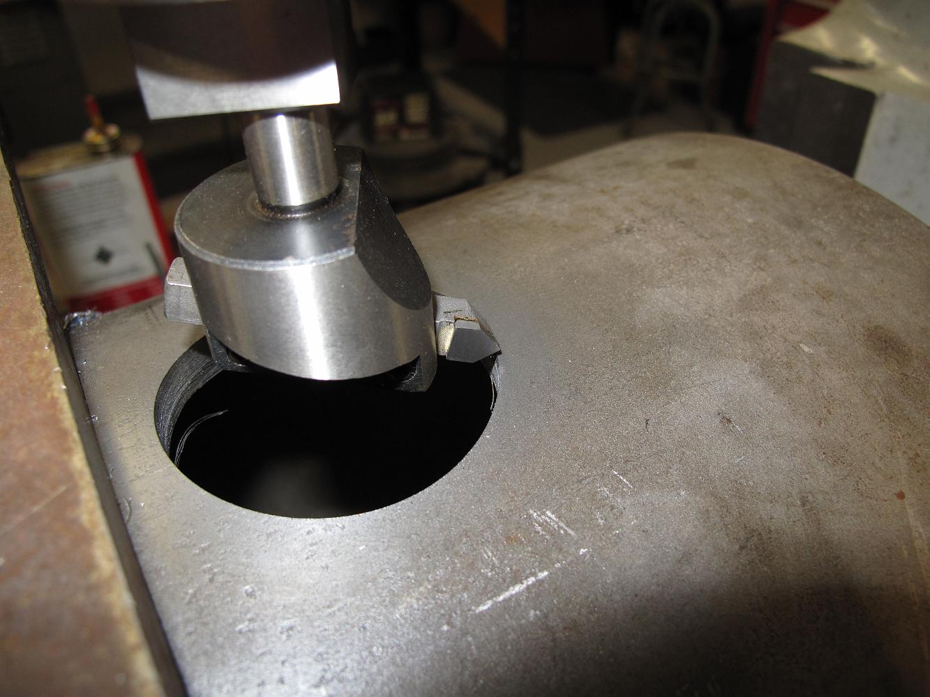
Having quickly reached the size limit of the boring head with boring bars, we start a progression of larger fly cutters mounted in the boring head to enlarge…
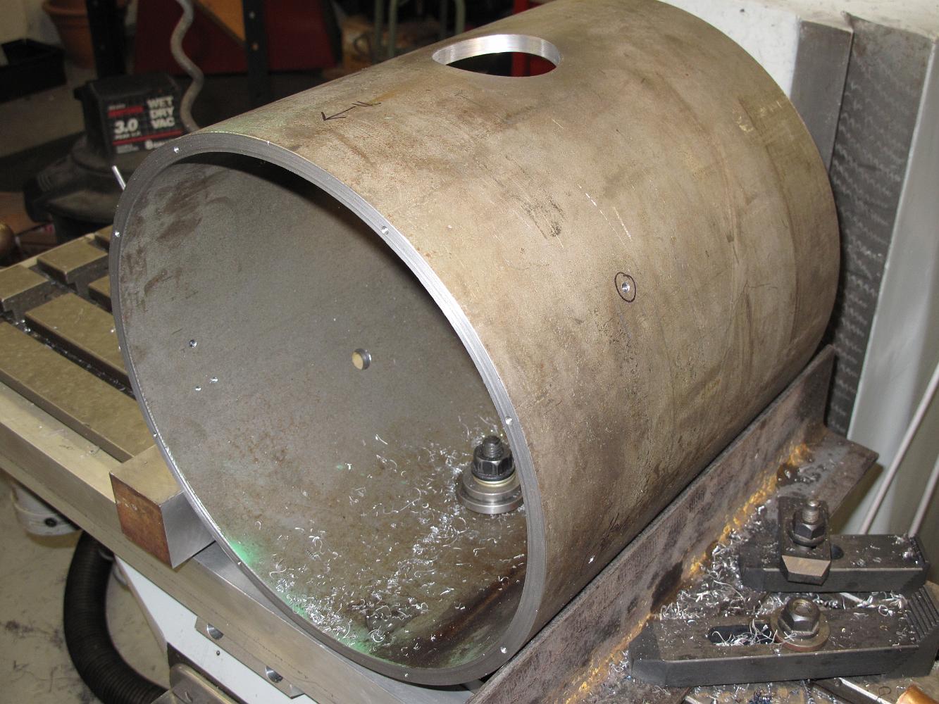
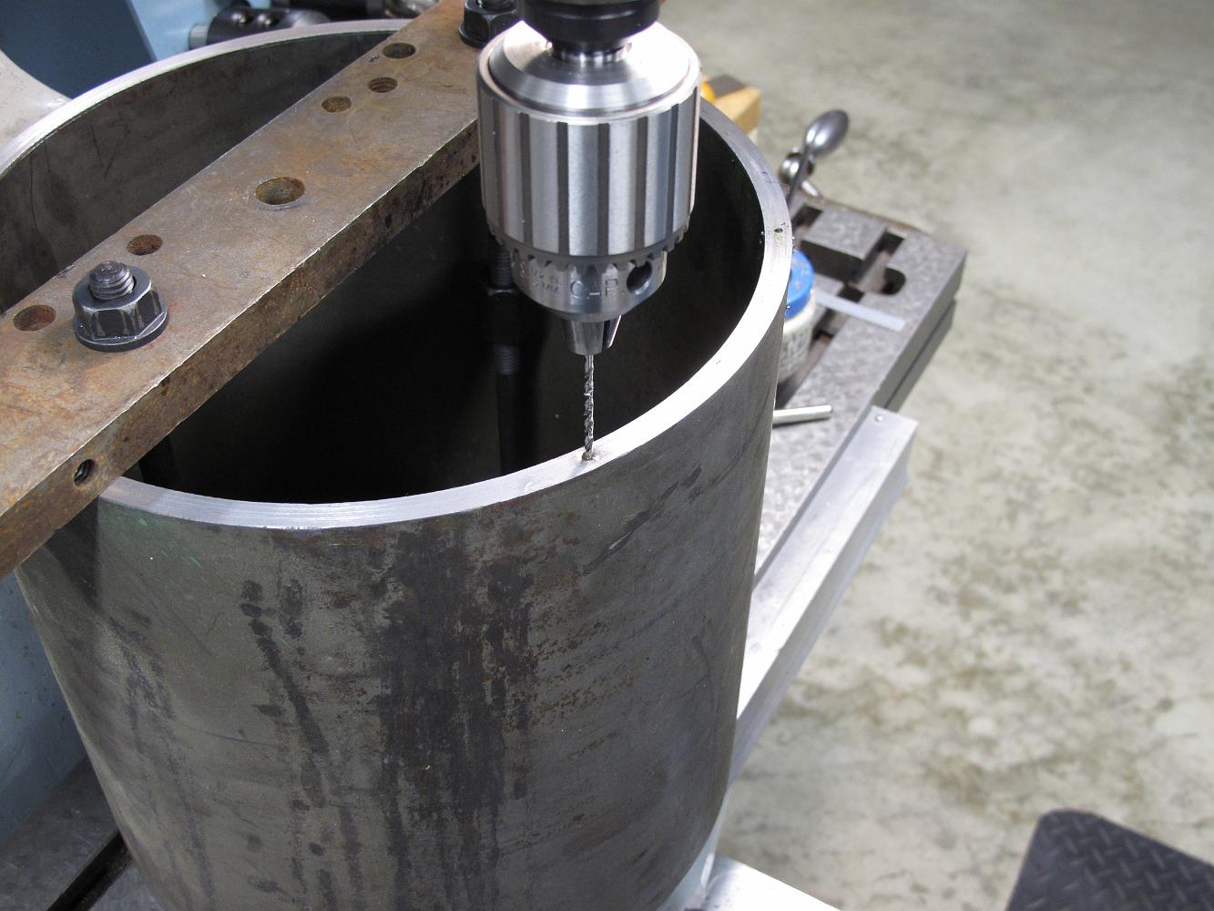
All the holes (not counting rivets) are done except for the smokestack hole. We add a center bolt in the blast pipe hole to help secure the pipe and start a…
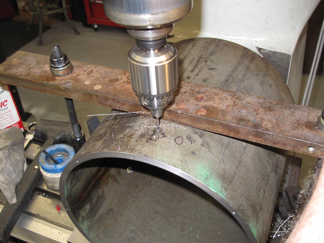
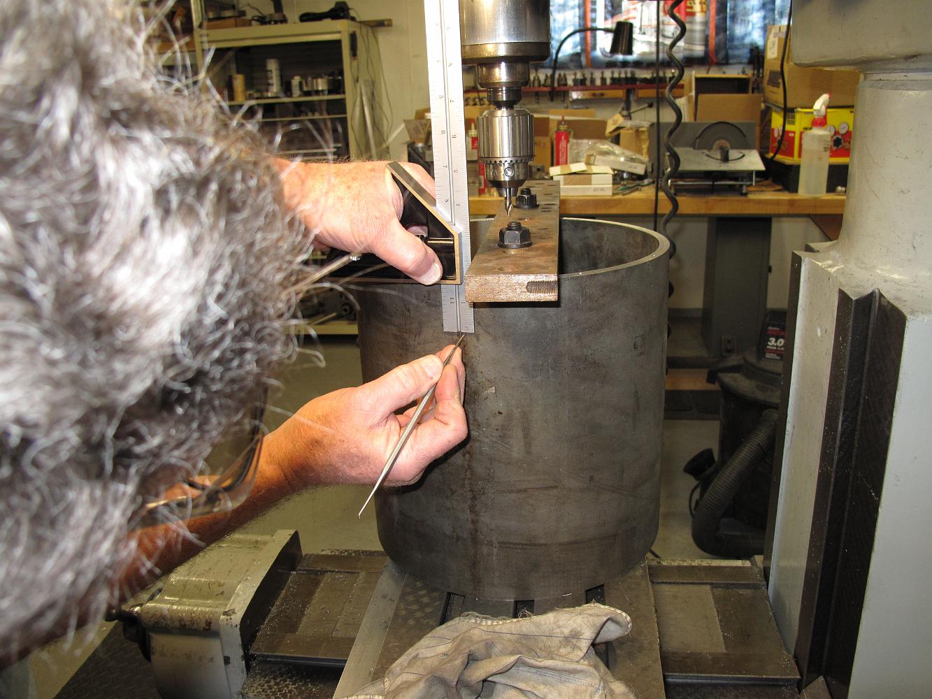
After a hole is drilled, we loosen the top bridging clamp, roll the pipe and line up to the next scribe mark. Here we are drilling the holes for the side step.
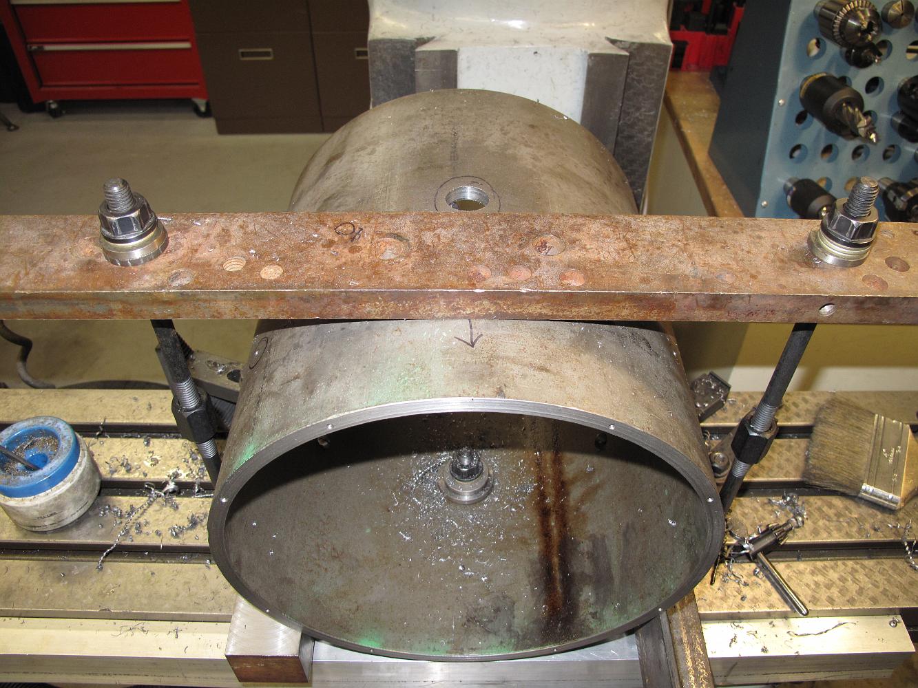
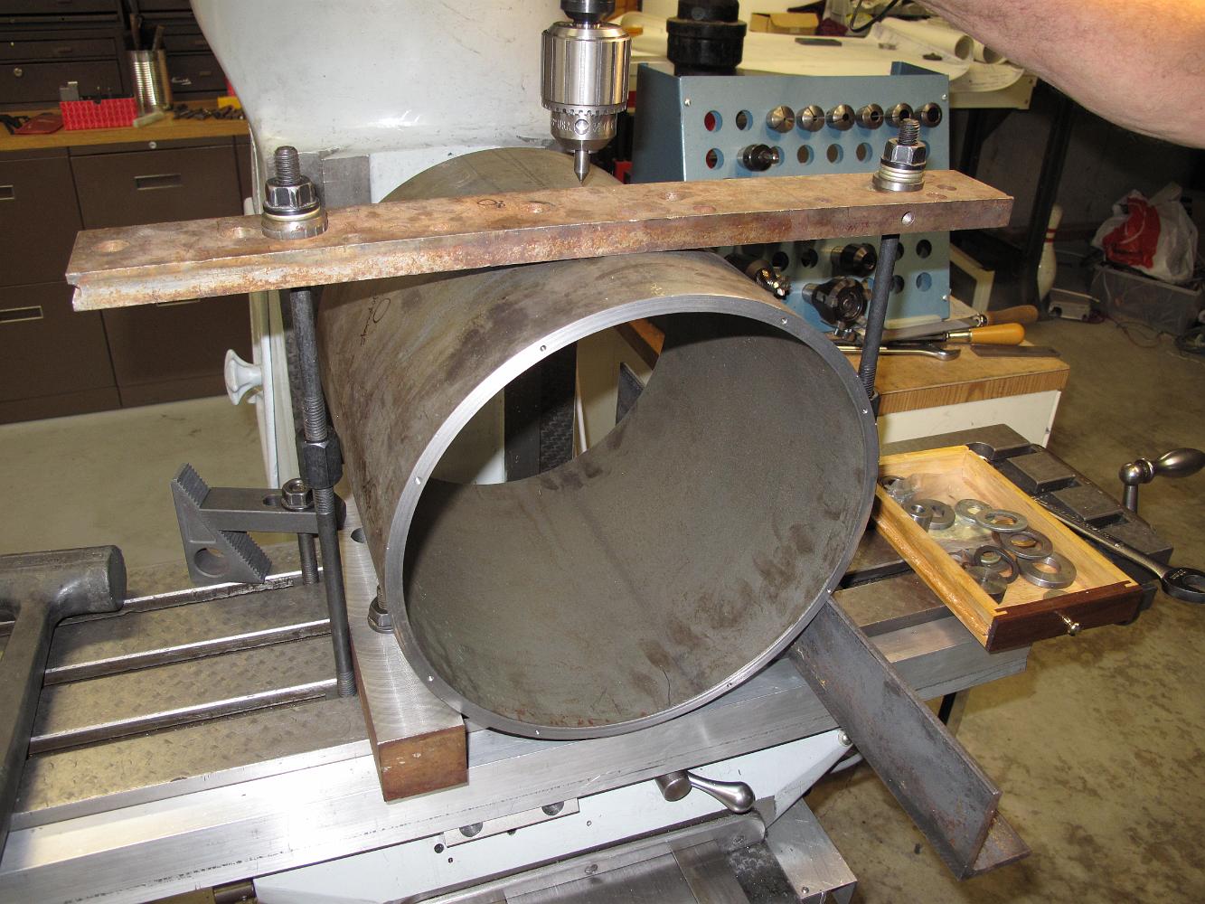
With a 4" piece of angle channel on the other side and a piece bridging the top, we have a secure hold on the pipe, but only for light cuts. Before starting to…
Next to make a clamping fixture. My mill table is way too small to clamp over the shell by resting it in a slot, and I probably couldn't lift a vee-block large…
21-Feb-09 It's lousy weather outside today, nothing can be done at the track so into the shop we go. Using the same DRO bolt circle program, we have made marks…
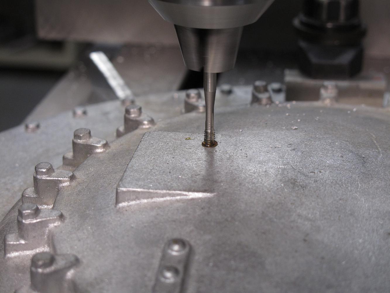
A bit of figuring with the DRO bolt circle program and soon we are drilling and tapping the 5-40 holes for the smokebox cover.
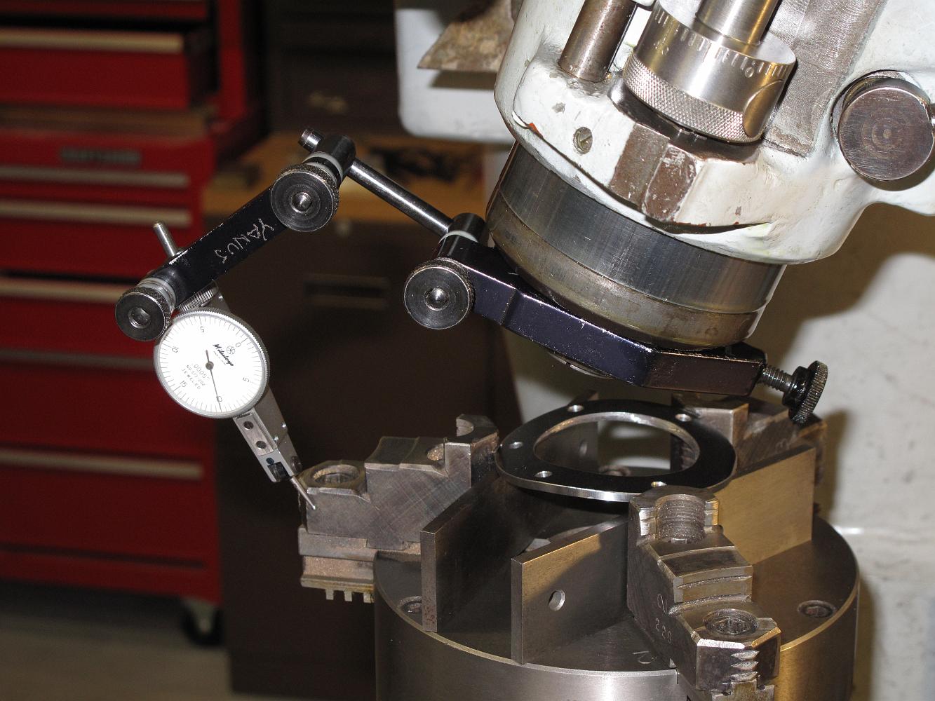
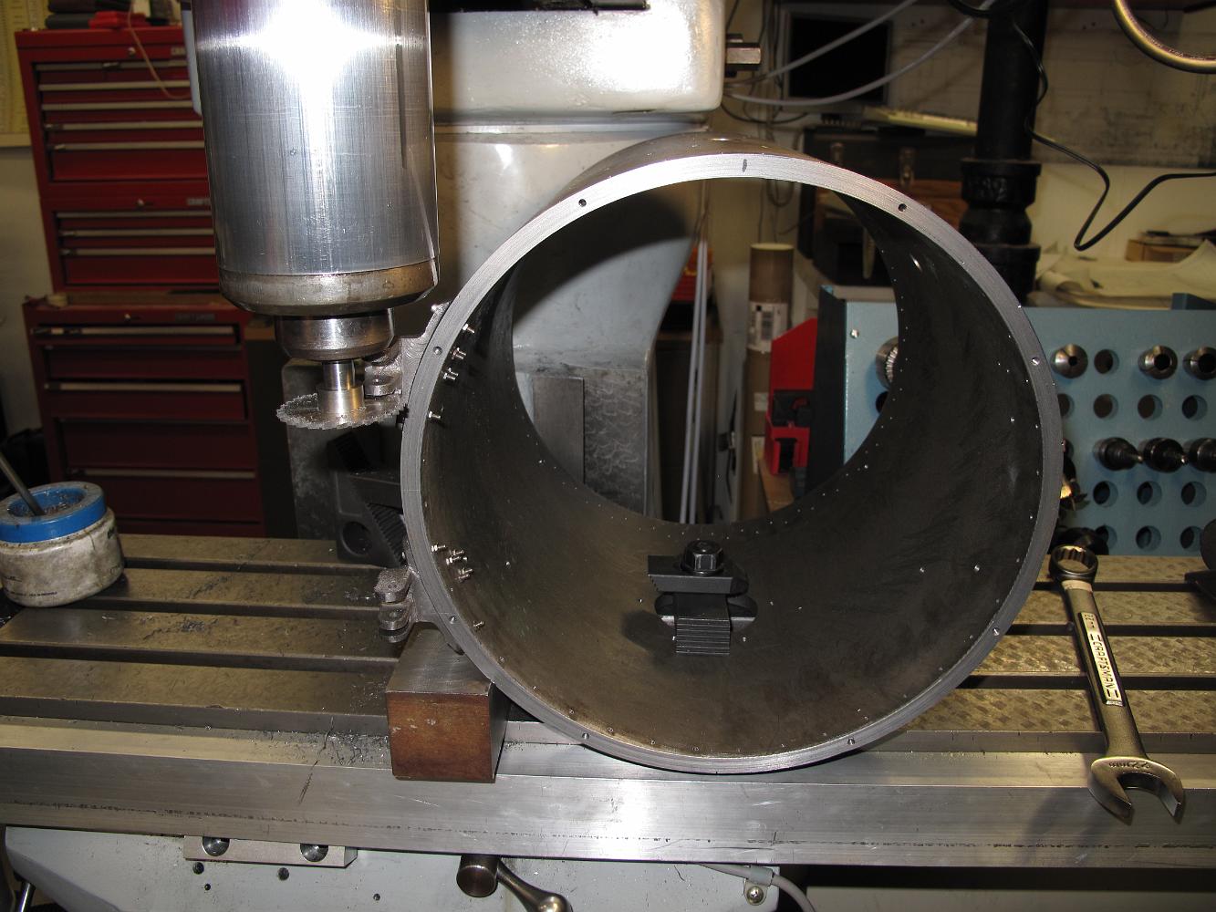
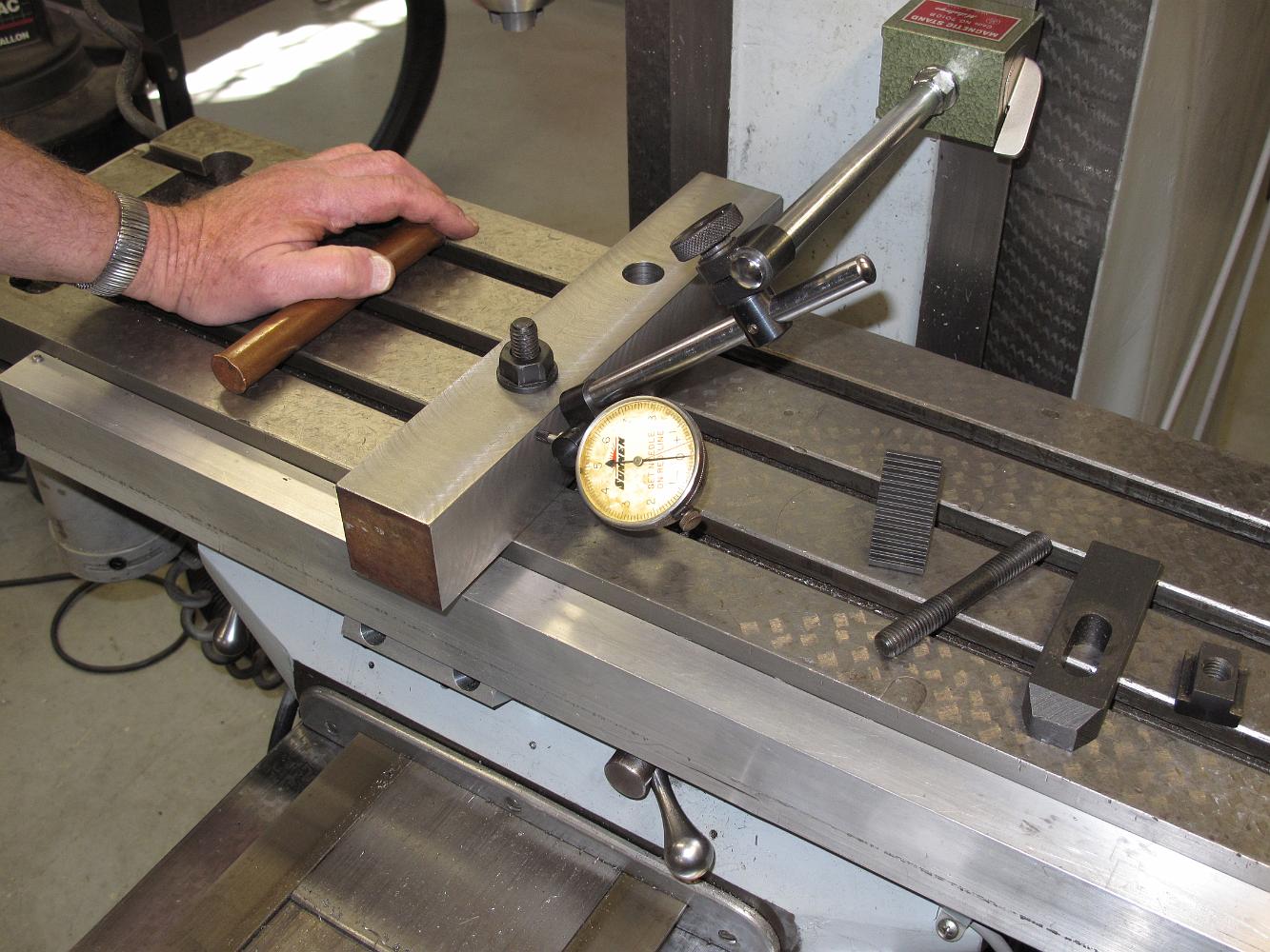
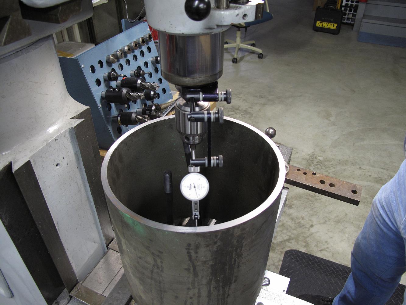
With the Bridgeport knee all the way to the bottom and the ram pulled out a bit more, we do our best to center the pipe in the mill. We discover the pipe is not…
Finishing the centering operation with the dial indicator. Next we clamp down a nice sharp piece of high speed steel in the lantern style tool post and face the…
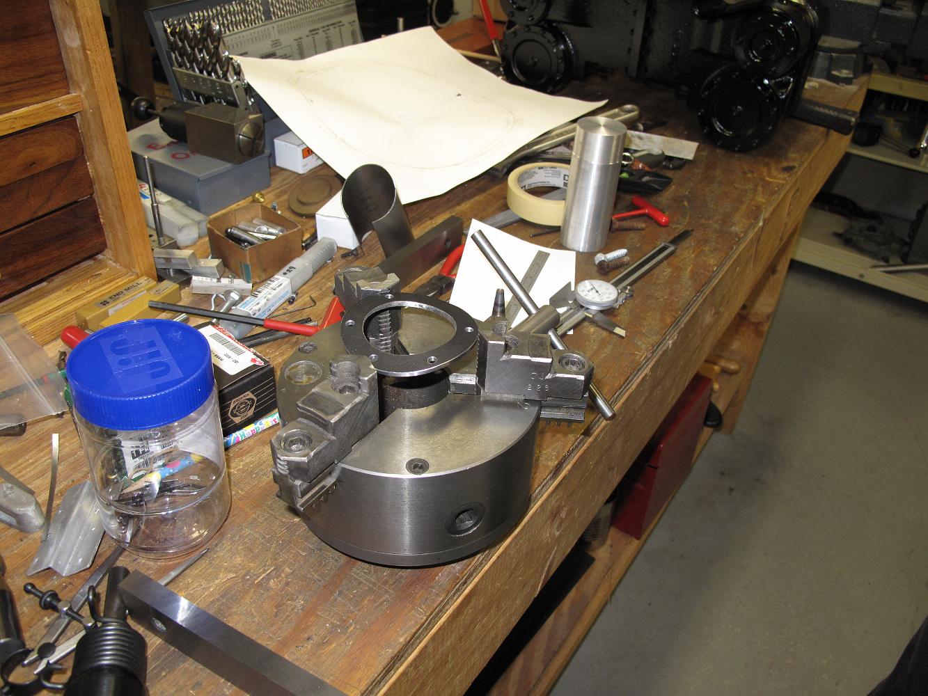
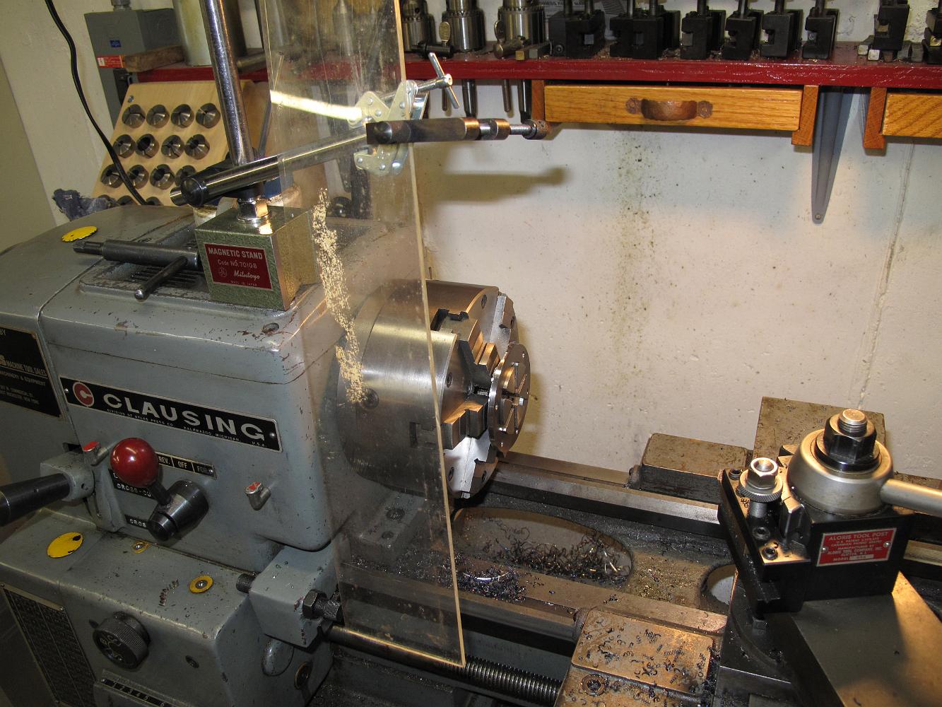
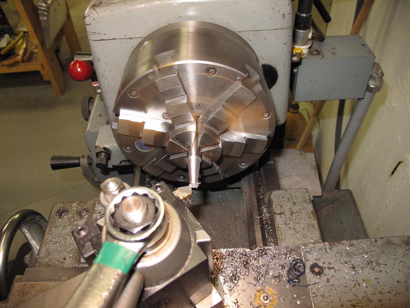
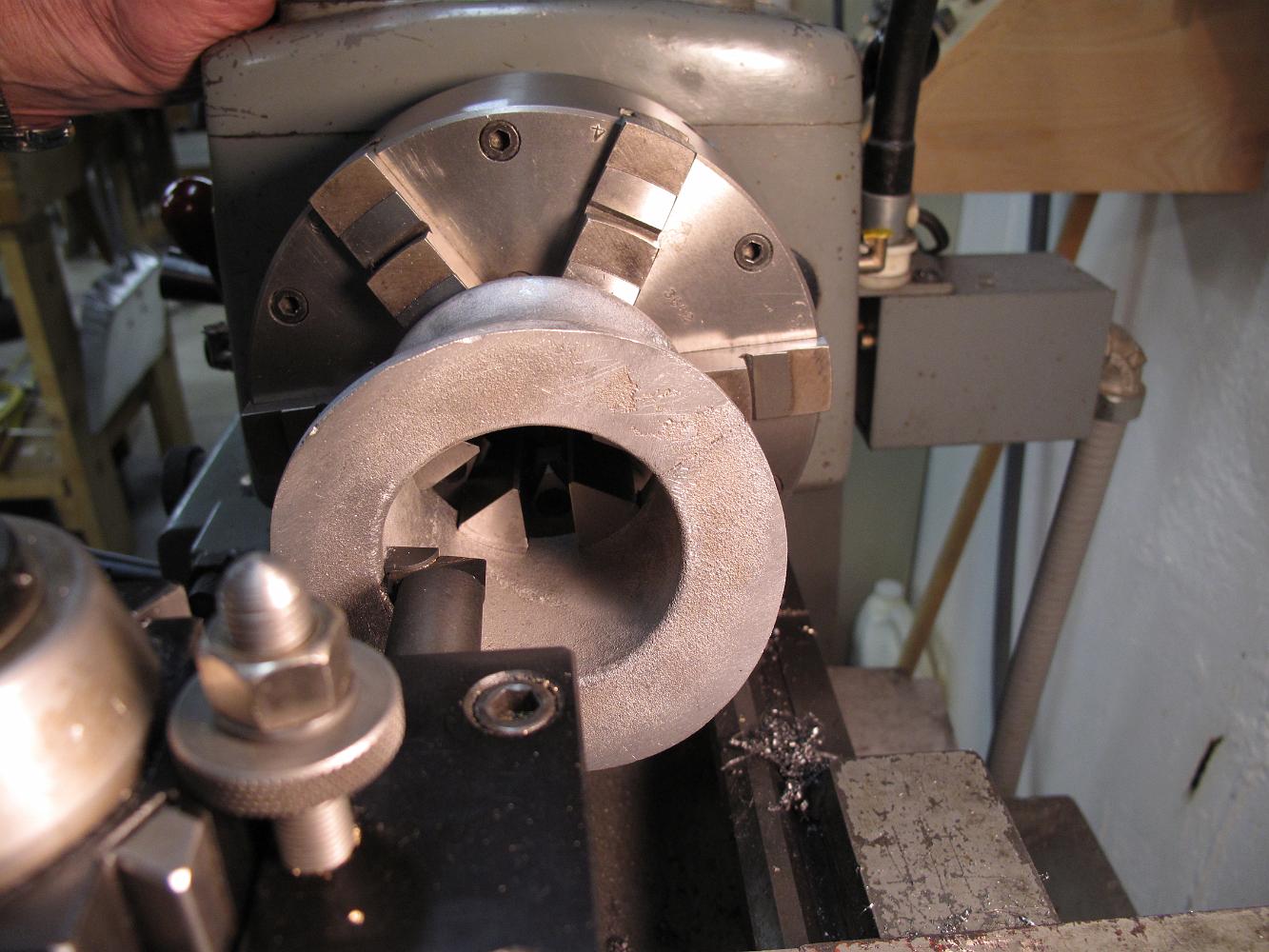
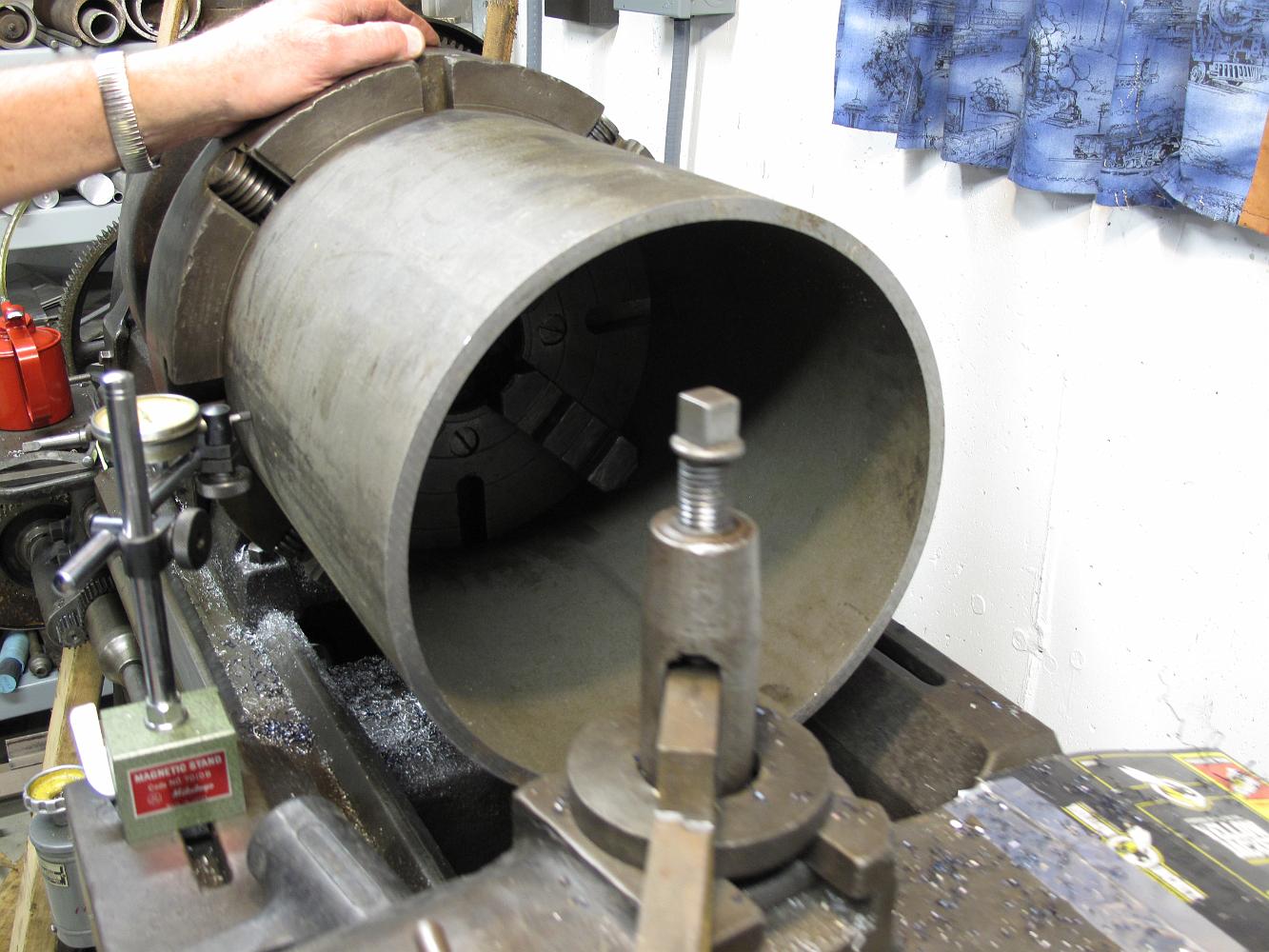
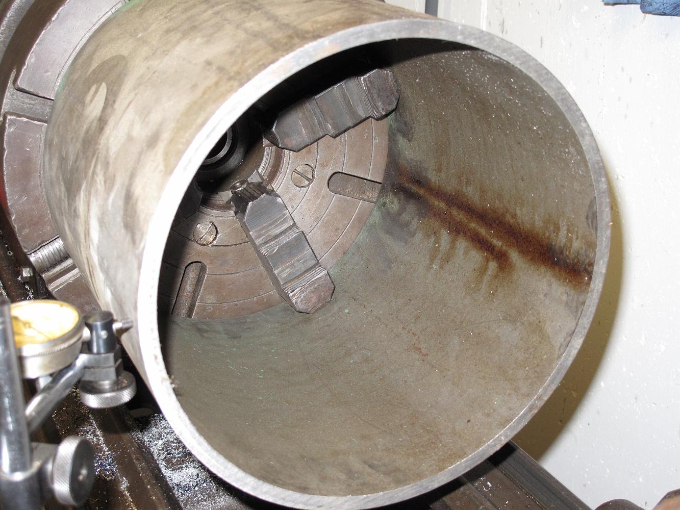
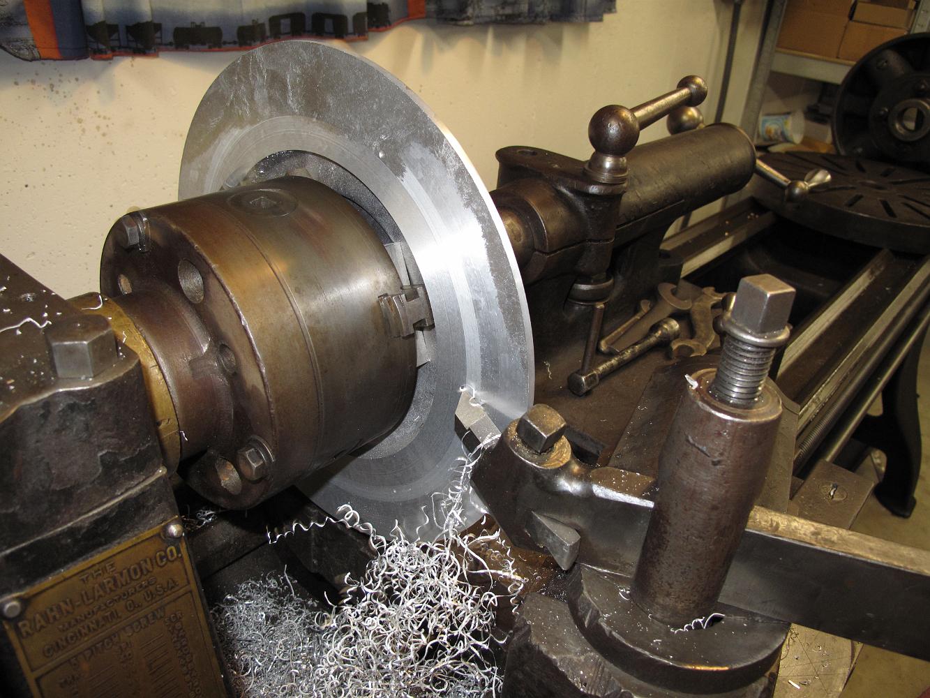
11-Feb-09 This old Rahn-Larmon lathe still has the factory issued 14" 'Sweetland' (named after the inventor, William Sweetland) chuck with it. 90 years later…
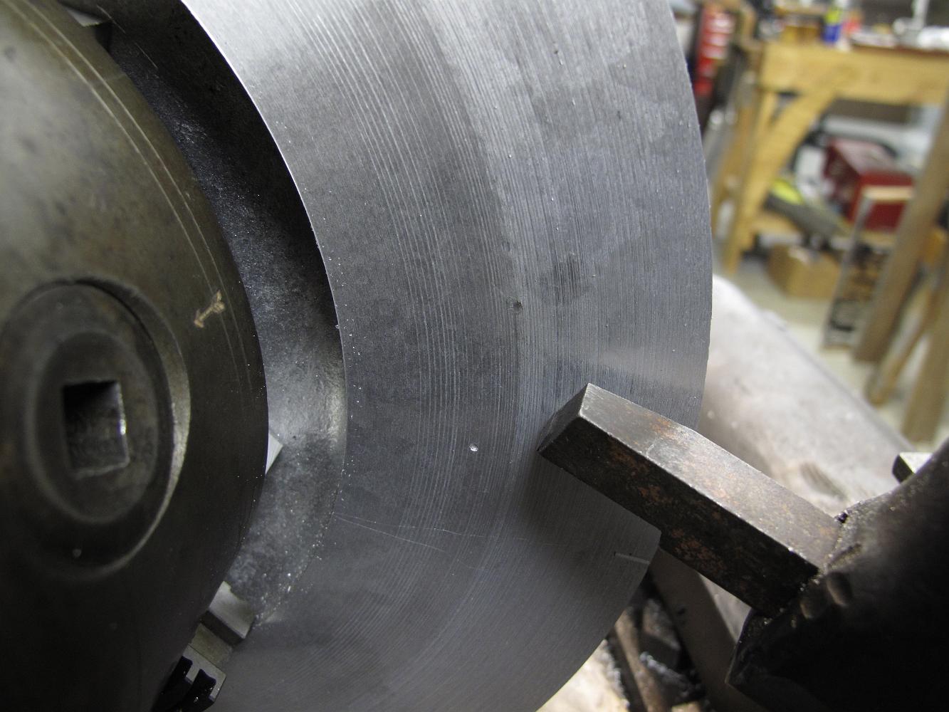
The cutting was going well until we hit a piece of sand or a stone in the aluminum which destroys the edge of the HSS cutter. You can see the defect in the…
Running in open belt, about 258 rpm, we take light cuts from the inside working out with a nice sharp high-speed tool bit.
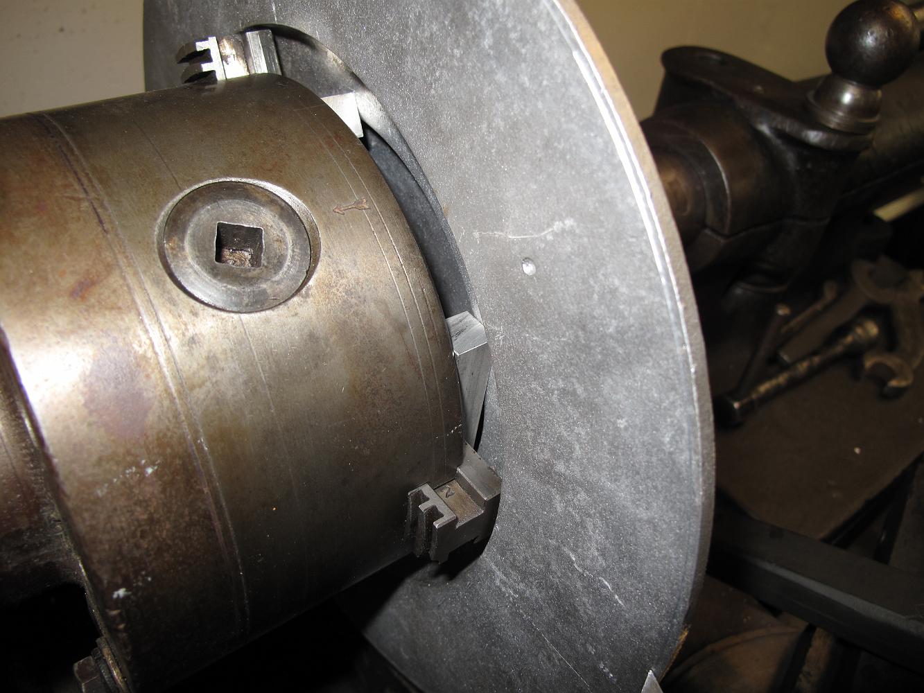
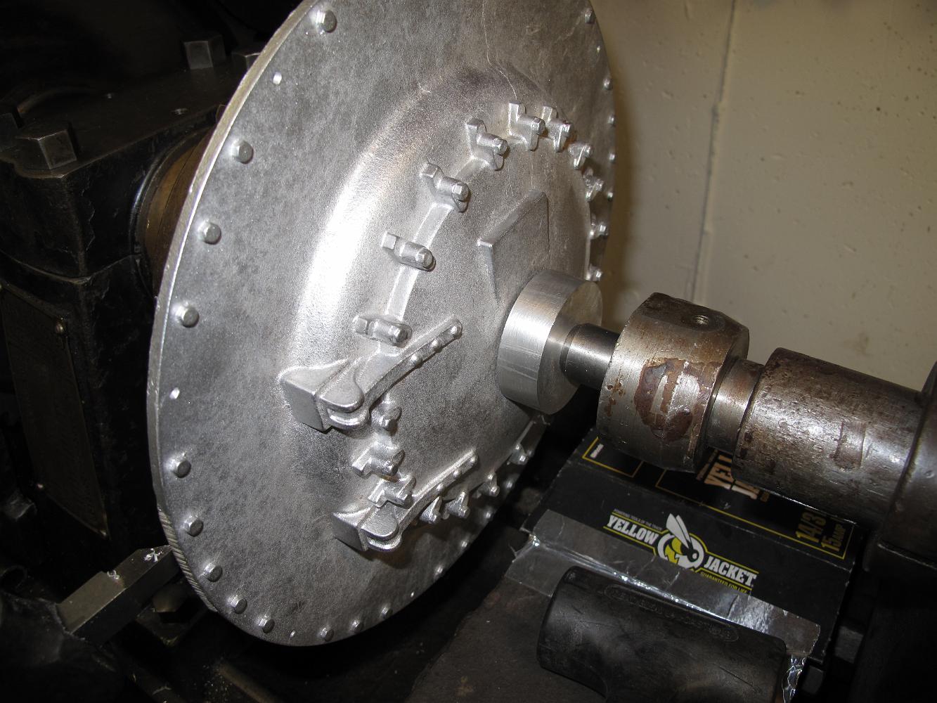
Here's how we chose to hold the smokebox front: Using a 6" 3-jaw chuck with the removable jaws off, putting 1/2" square stock in the jaw alignment slots to hold…
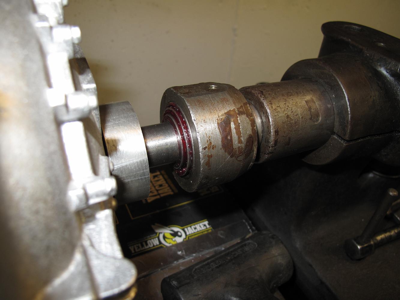
Our 'live center' is a shop made affair of many years ago using an open cage tapered roller bearing. I had to dunk it in the solvent tank to clean out the gunk…