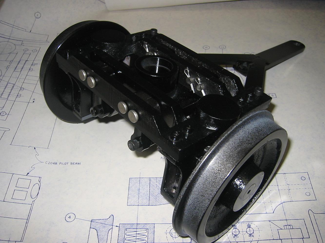
26-Oct-08 I couldn't help myself. Looking at the partially assembled frame without the front pilot truck appeared unbalanced, so I put the pilot truck together…
19-Oct-08 The painted chassie is put on the wheels and the delta trailing truck fitted underneath. Assembly is so much fun! But this isn't the final assembly --…
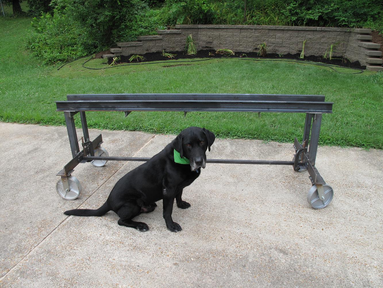
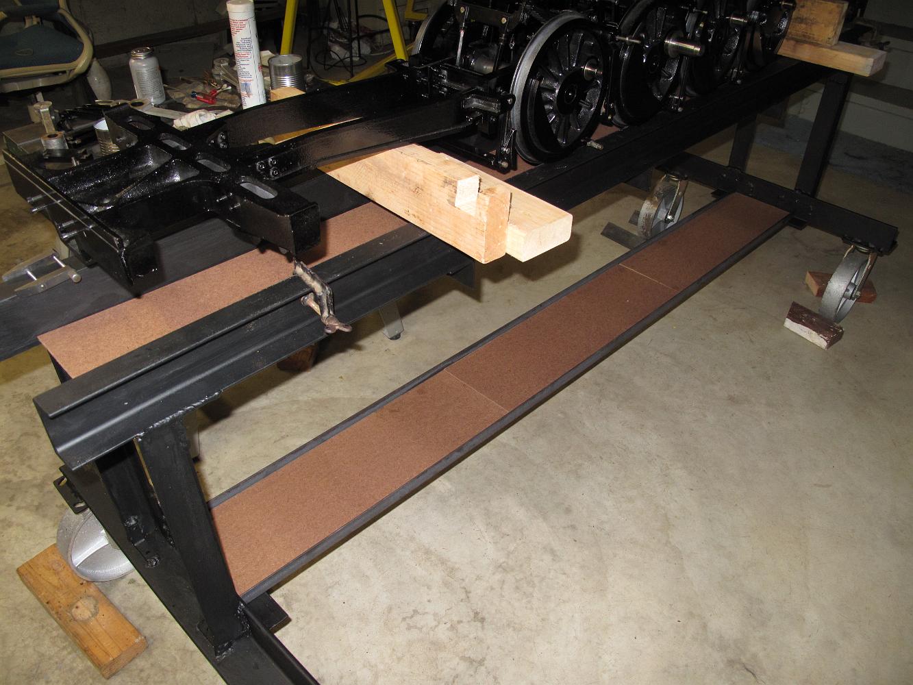
New Engine Stand
New Engine Stand
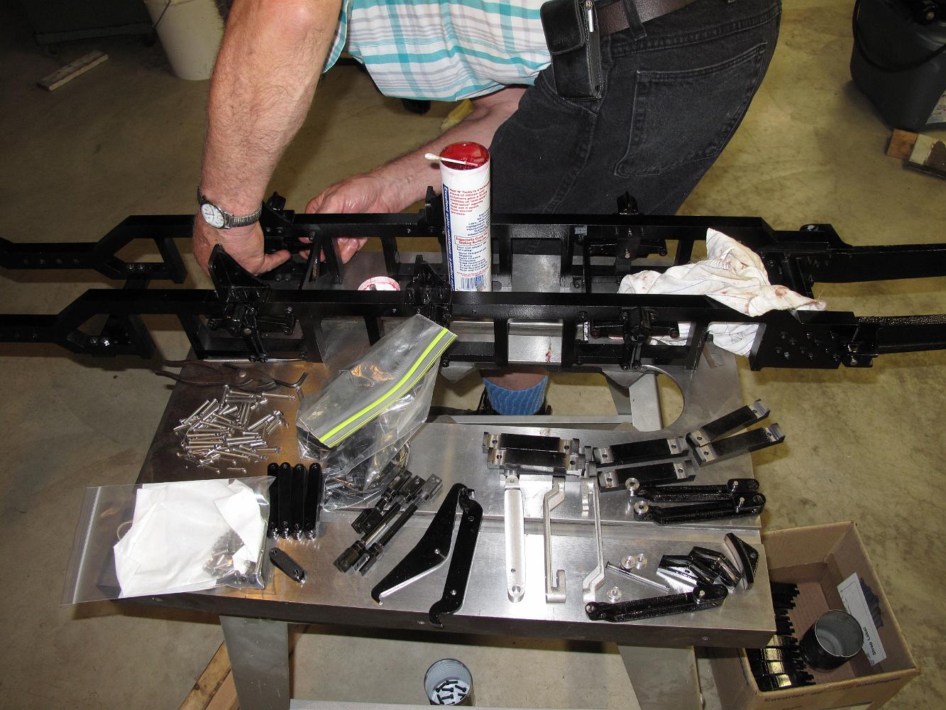
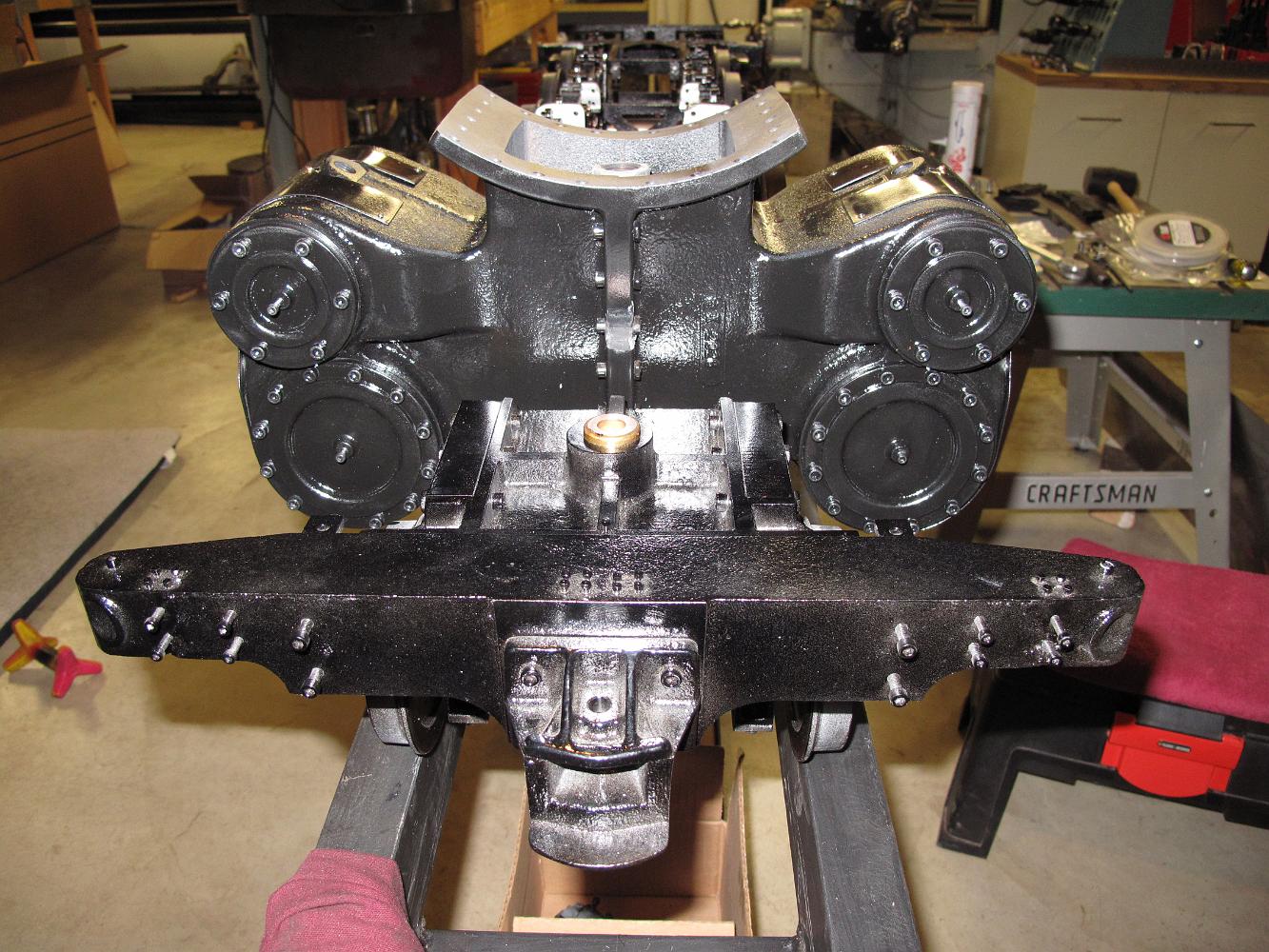
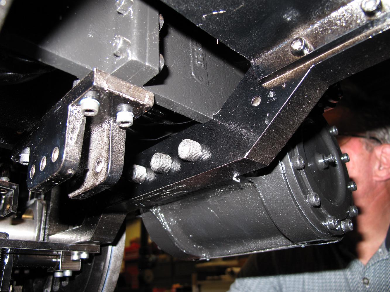
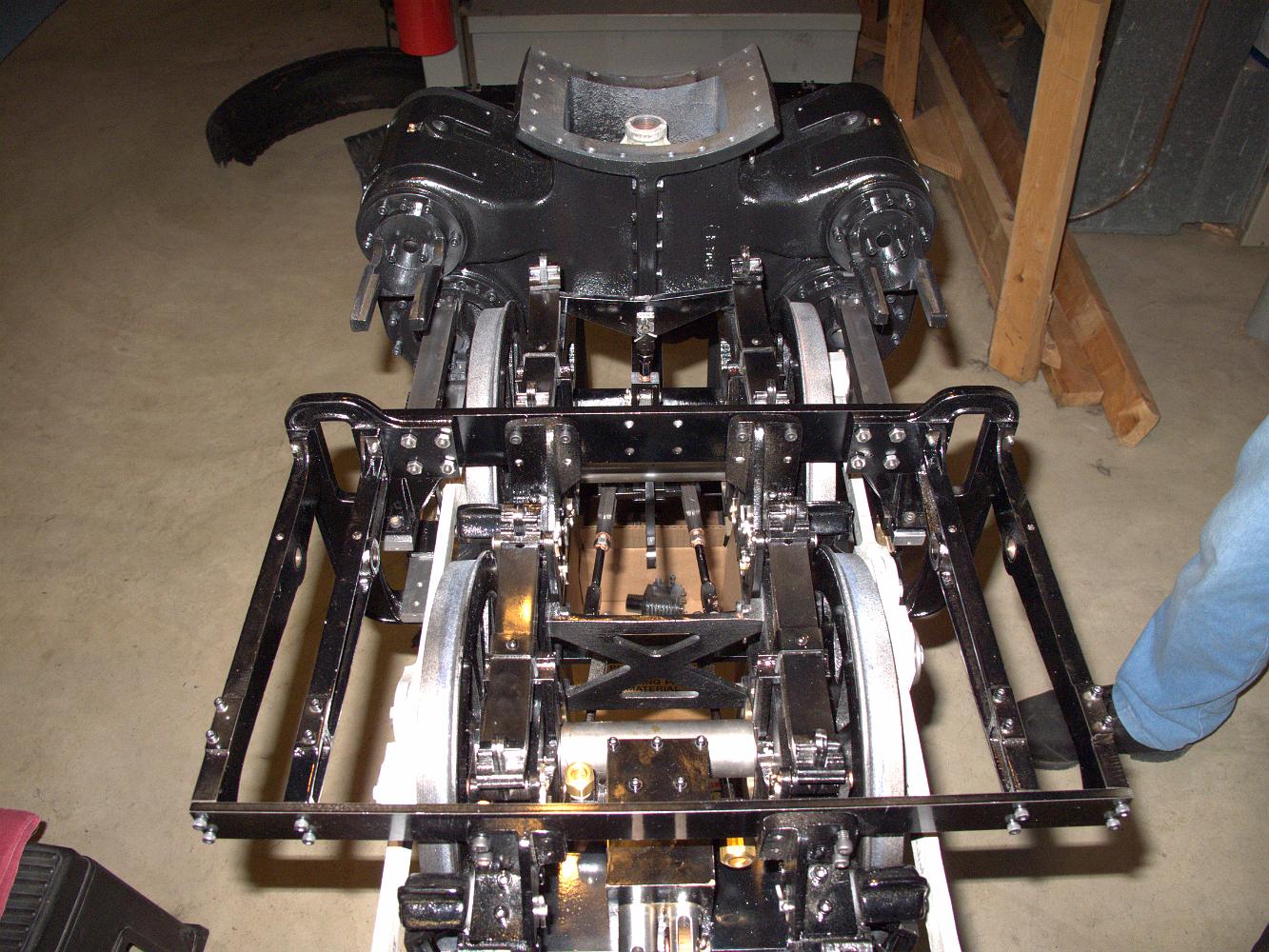
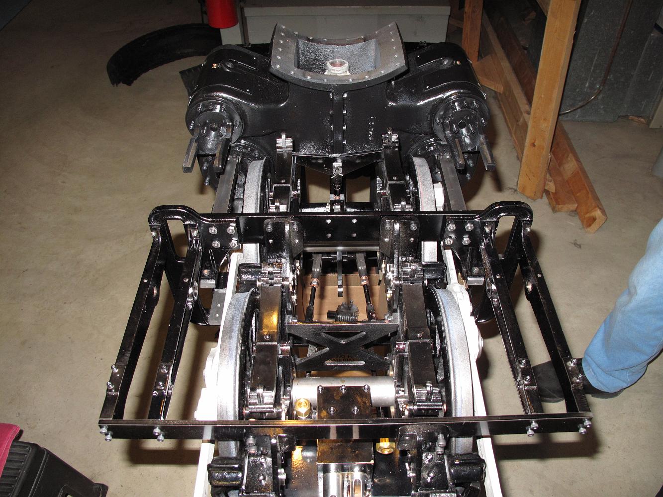
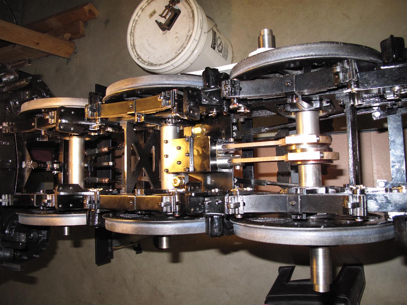
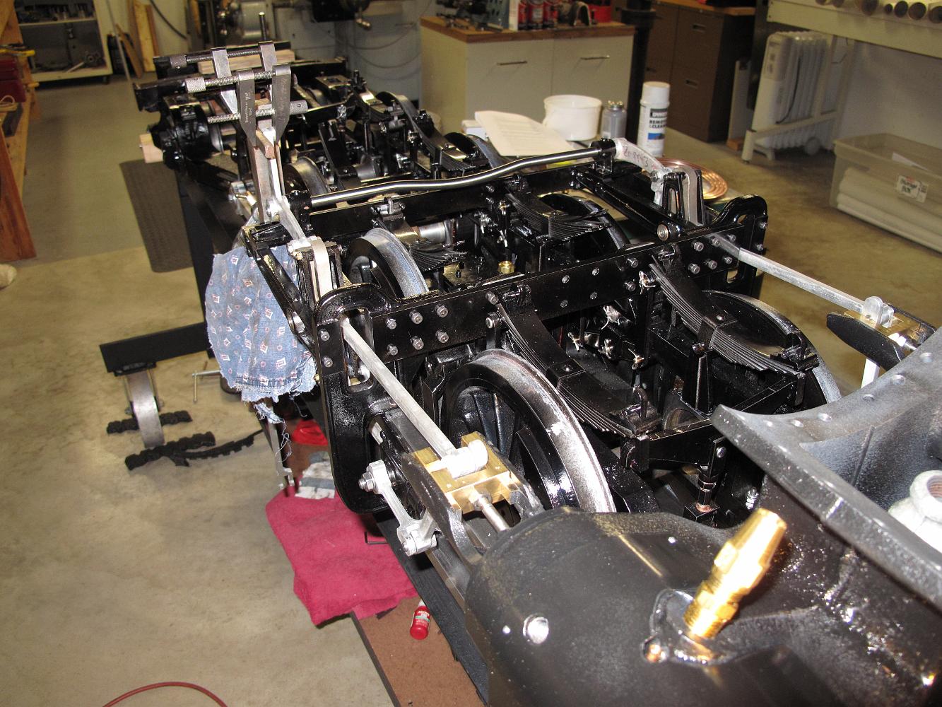
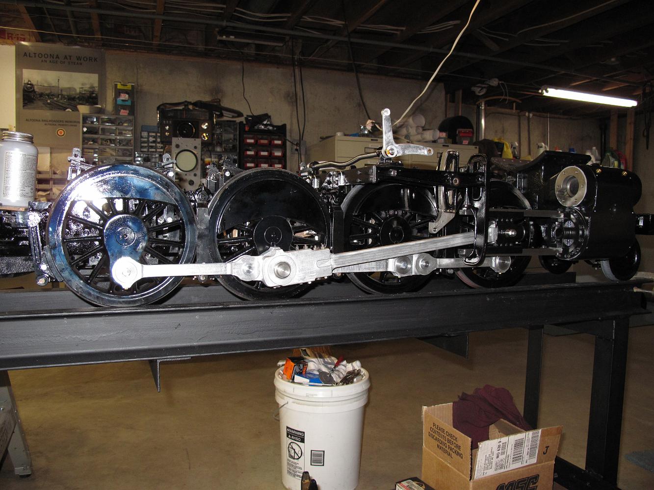
The frame sitting on the new Black 'low' stand with wheels and suspension installed. A note for the future: you have to install the brake hangers and brake…
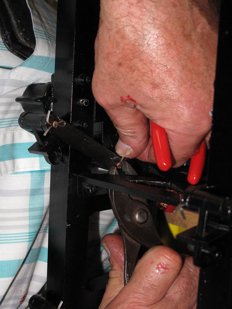
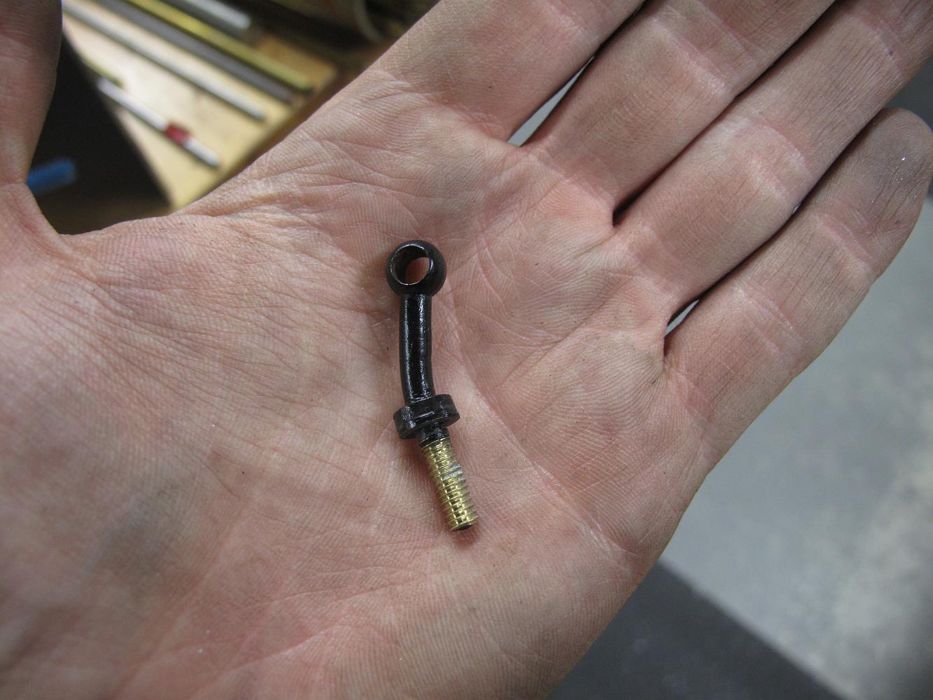
One more cotter pin bent, 47 more to go. These little 1/16" pins are tough to bend! And no, that is not blood on Bill's hand, but Red Grease, a lubricant we put…
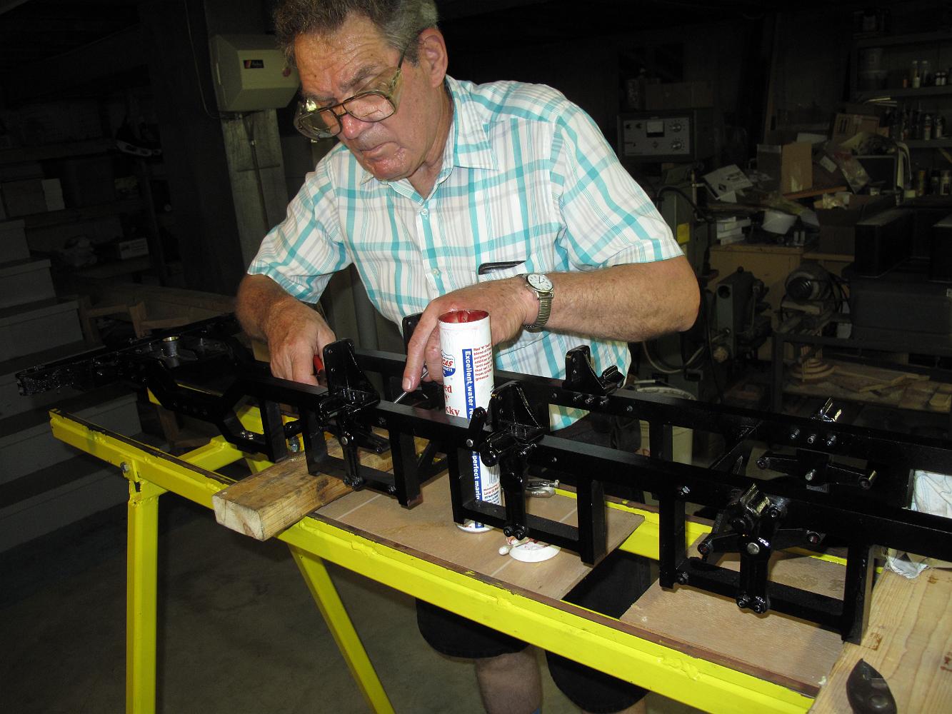
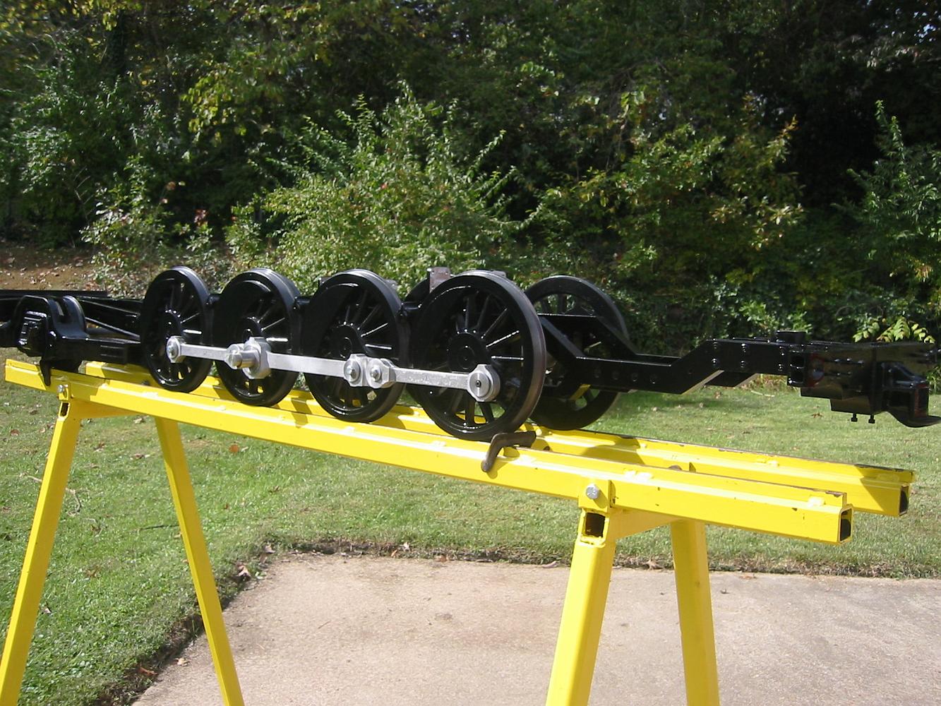
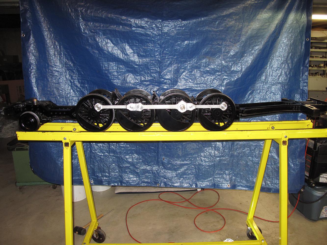
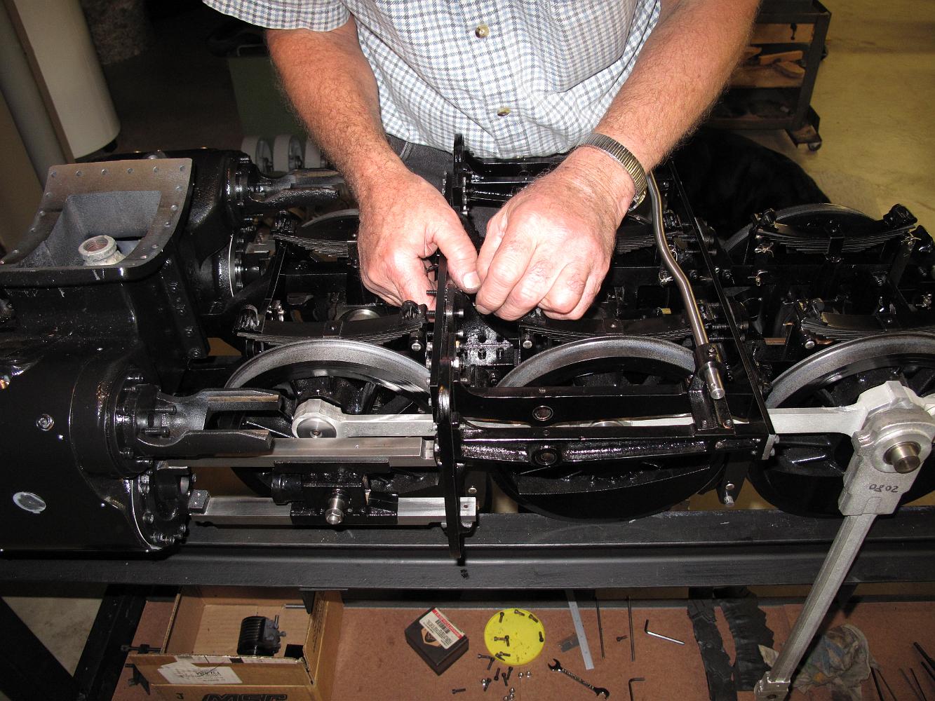
Installing the springs and equalizing arms. We are temporarily using the high 'yellow' stand instead of bending over a lower bench.
Installing the equalizing arms in the frame on a temporary stand.
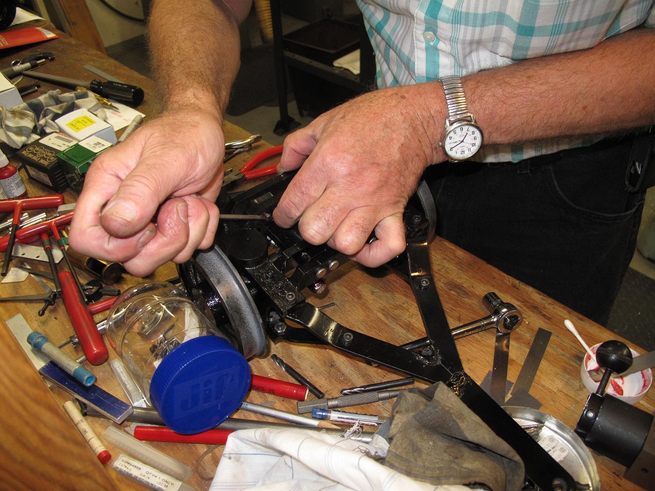
8-July-09 Assembling the Front Truck.
13-July-09 - While Mom and Dad were visiting me this weekend, I had Dad cut some hardboard up for removable shelves on the stand.
Add the trailing truck next. Work on shortening suspension pins on the trailing truck before that can be put underneath. Also discover the brake hangers and…
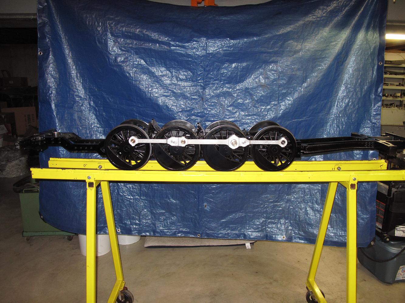
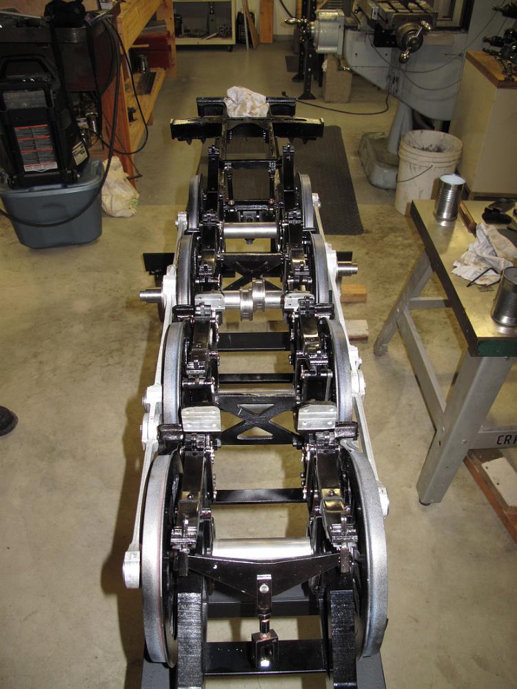
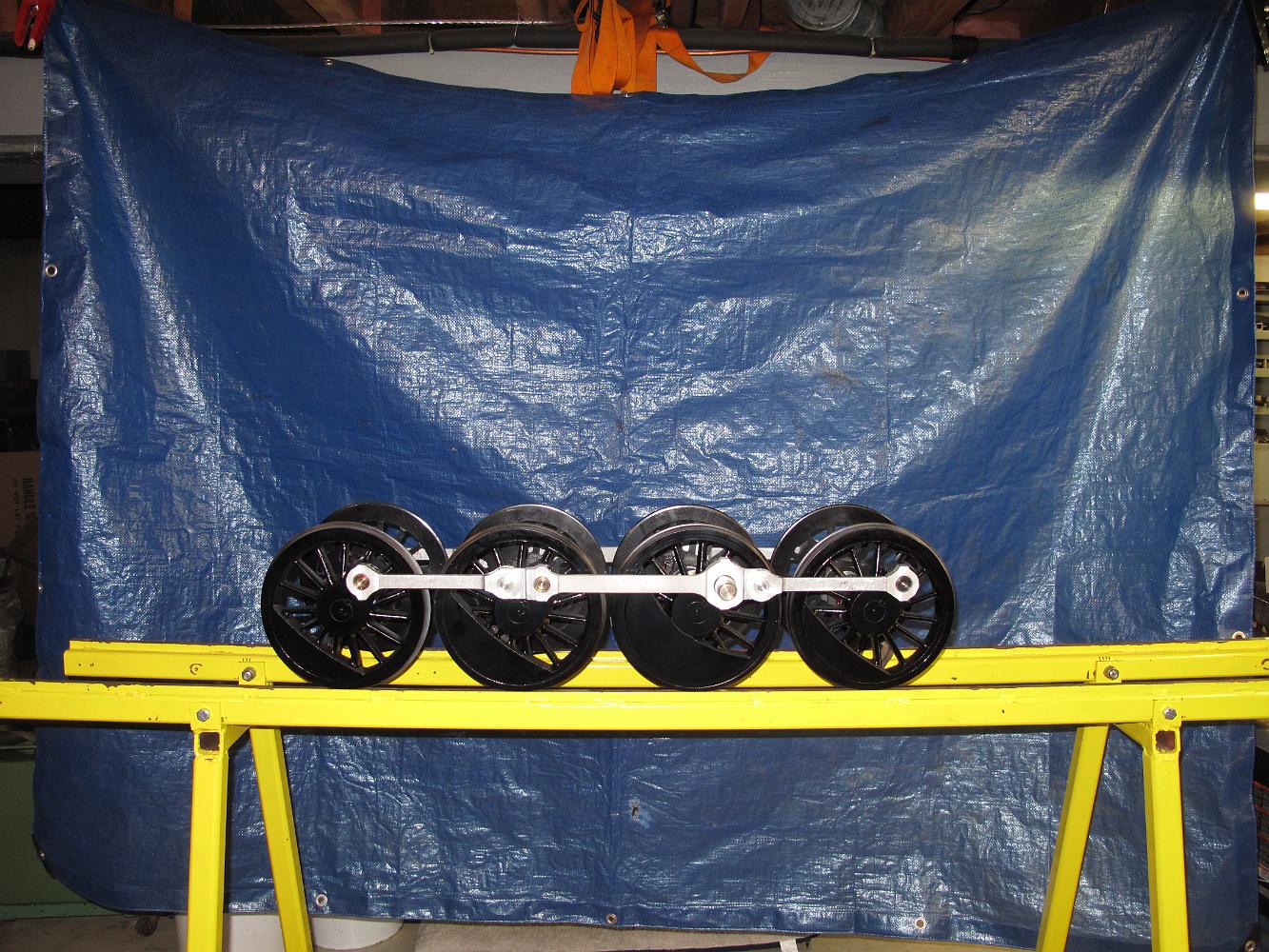
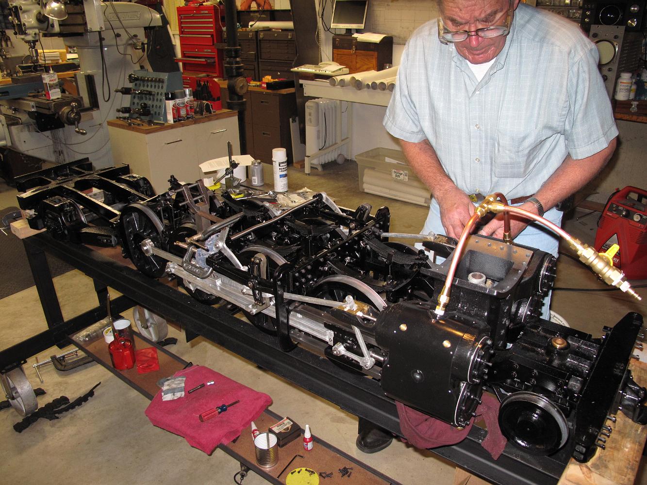
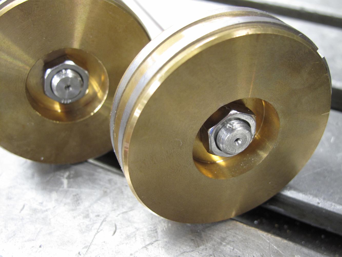
We start assembly with the wheels under the frame.
4-July-09 A very wet Saturday morning put bill and I down in the shop and not out at the track. We start assembly!!! Yeah!
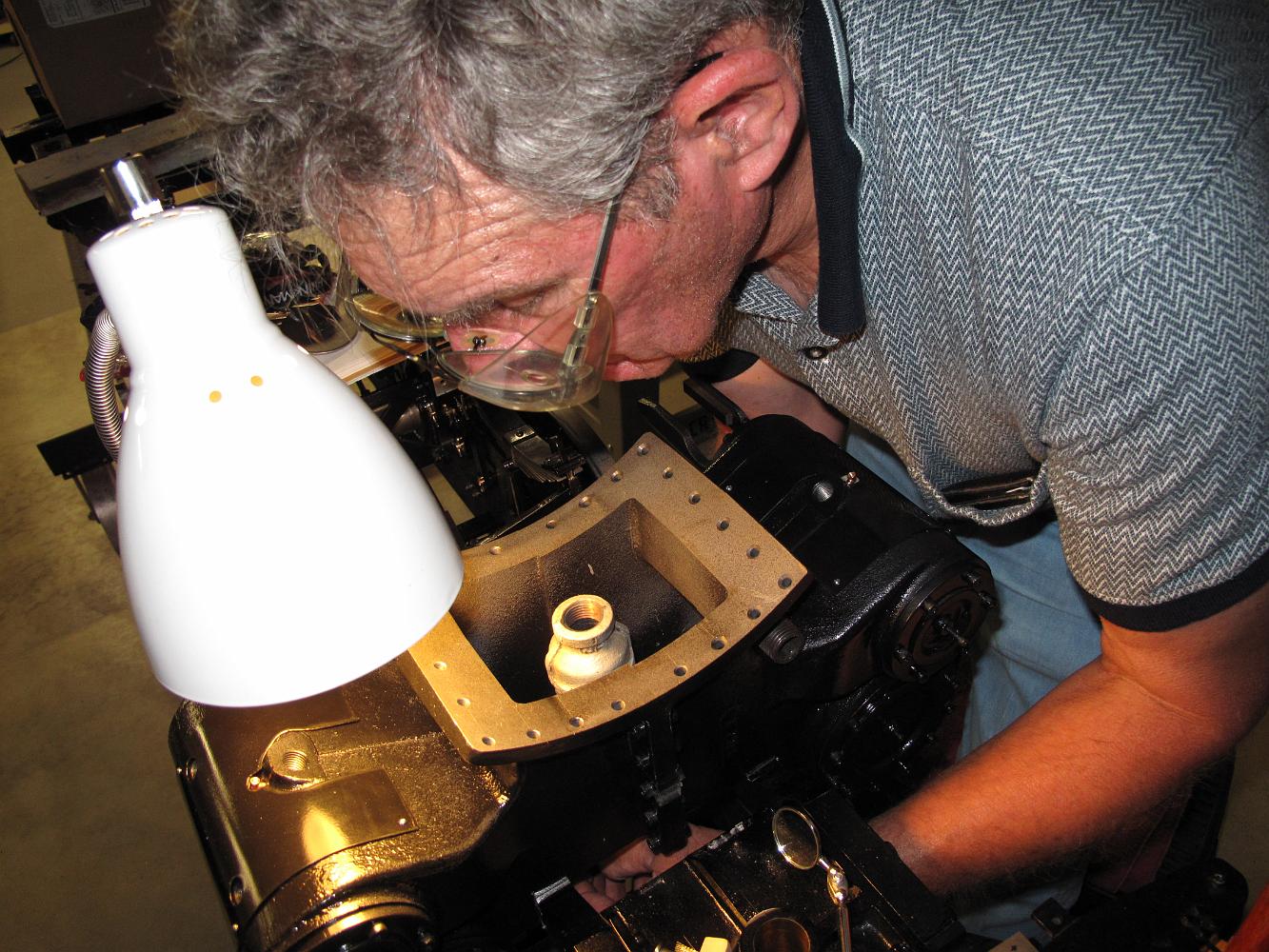
Bill works to install the cylinder mounting bolts.
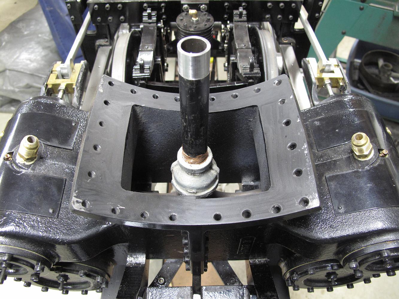
With the cylinder jacketing installed (we used drive rivets to hold it) we begin fitting the cylinders to the frame. We ended up with some height differences on…
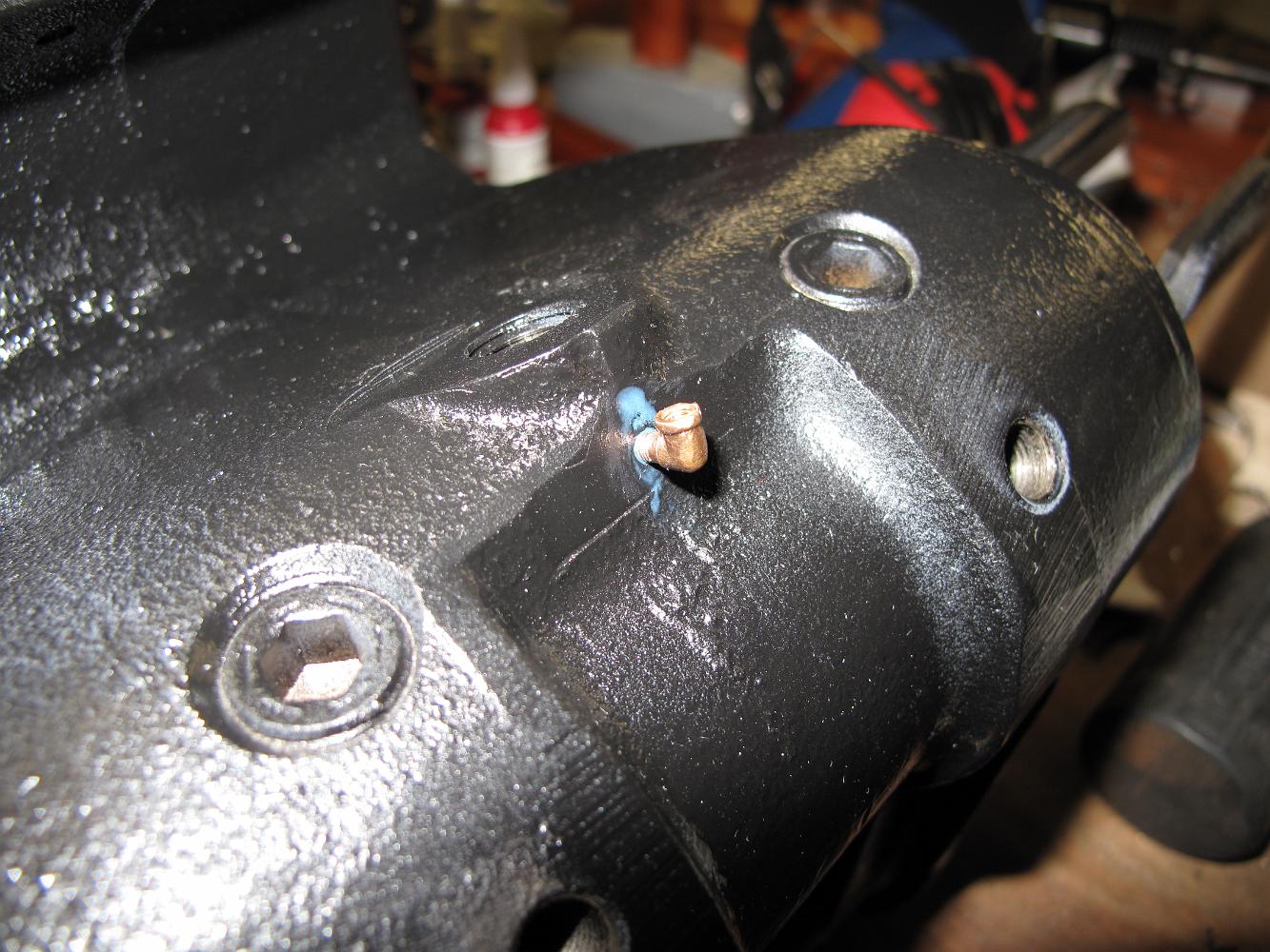
30-Sept-09 The tiny 1/8-56" street el for the lubricator line is screwed in and Loctited to the cylinders. Next we mount the cylinder jackets.
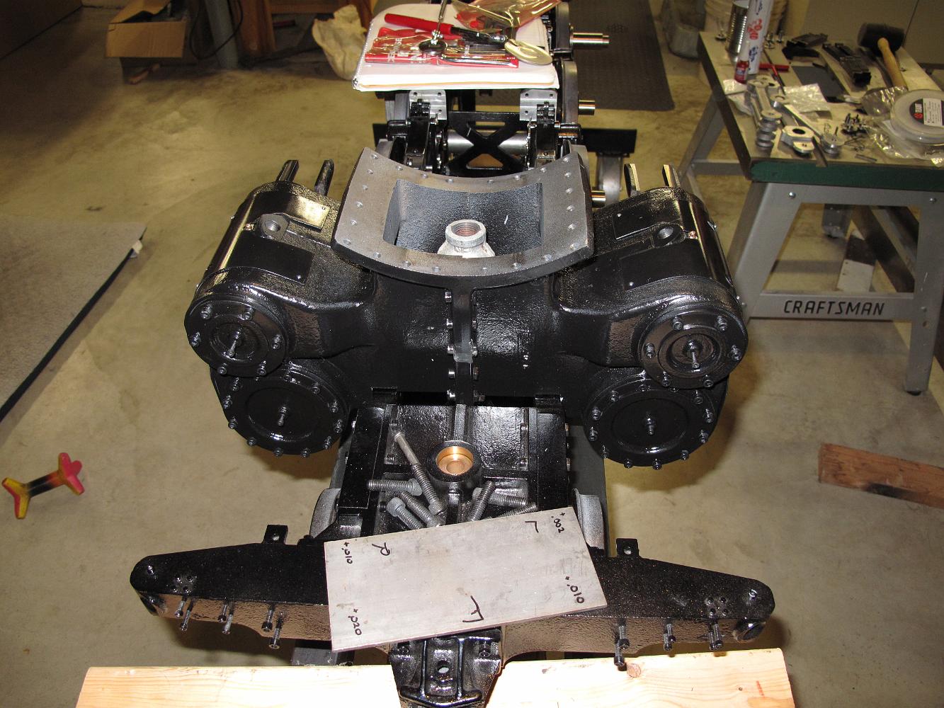
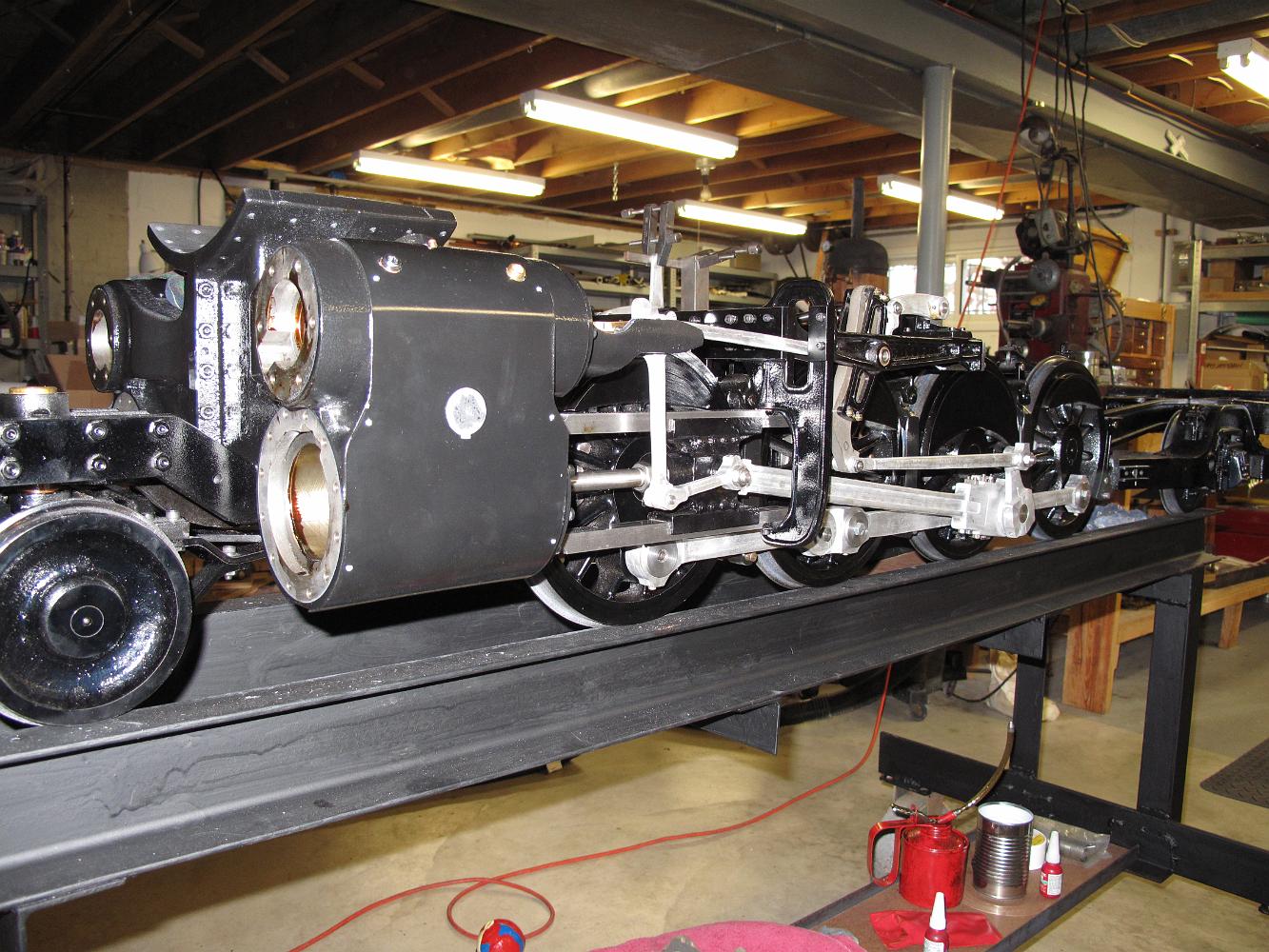
The front of the frame is much heavier now with the cylinders installed. I might have to make some paint adjustments - the frame has Sherwin-williams…
The bolts are installed with Loctite and very firmly tightened. They are one with the frame and I don't plan on ever taking them off.
Fitting the .064" thick aluminum shims between the Link Support Brackets and the Link Support Bars. For some reason the Brackets are too far back on the frame…
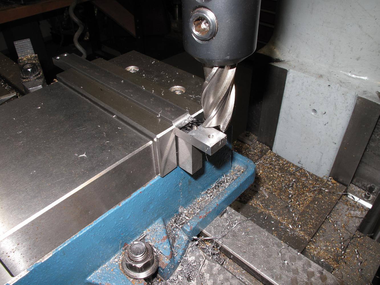
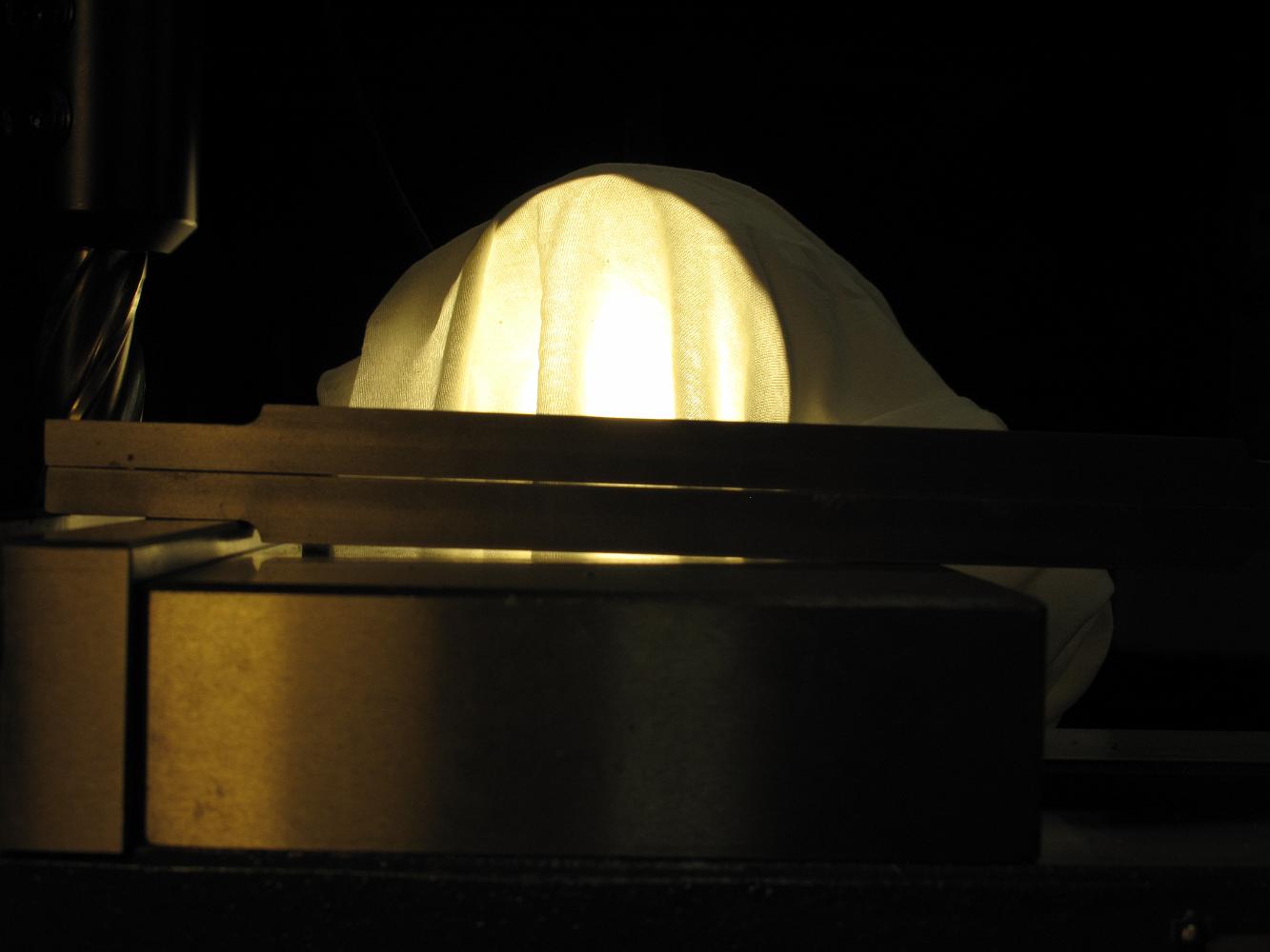
I probably shouldn't show this photo. Using the quill of a mill to unbend metal really is the wrong tool. This is where a press would come in handy to…
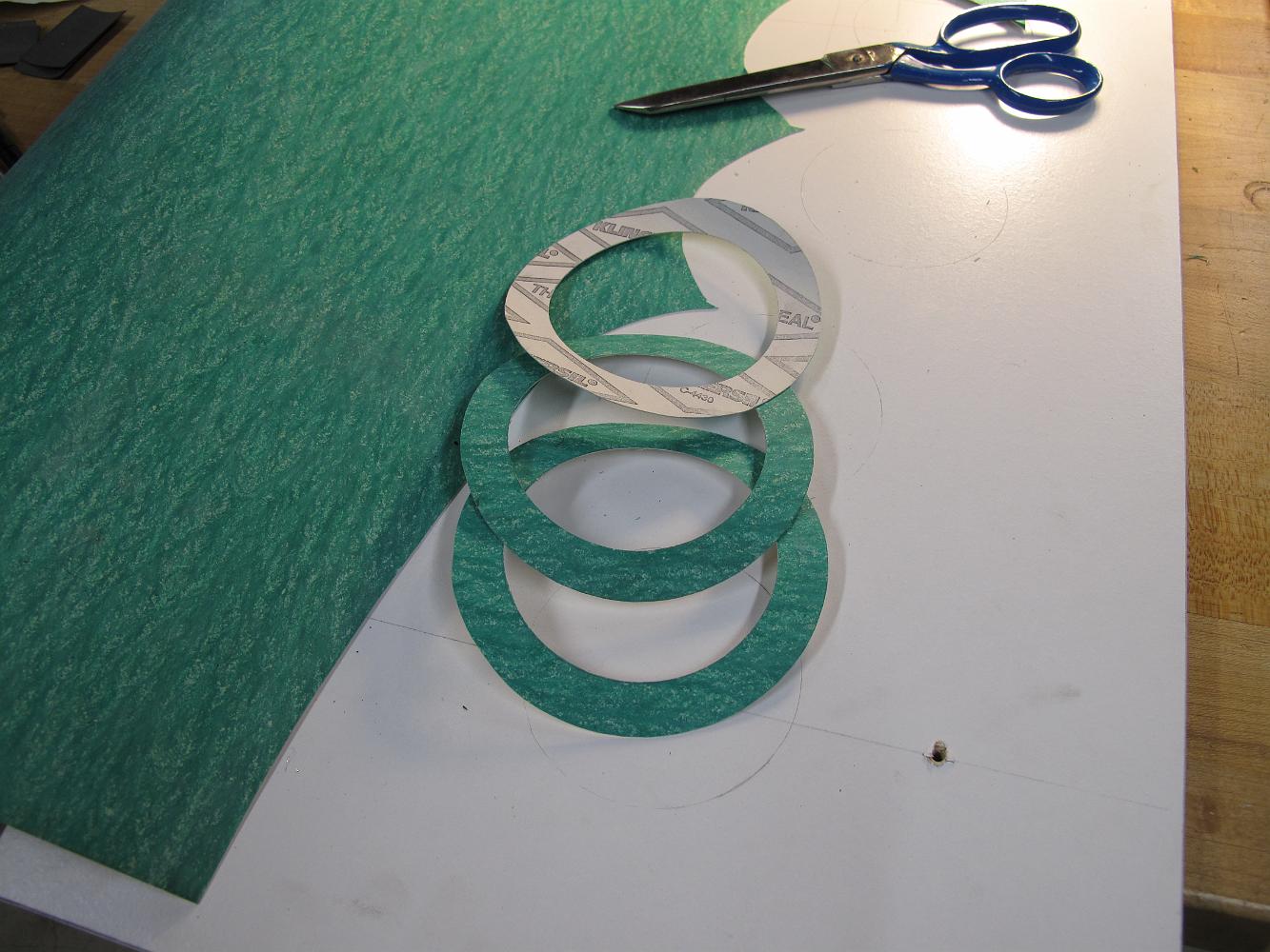
20-Oct-09 Getting the hole layout and punching the holes in the gasket is a two step process. First, using the aluminum template from the previous step, the…
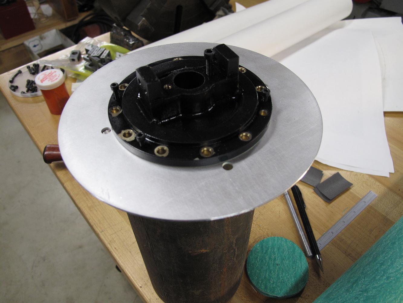
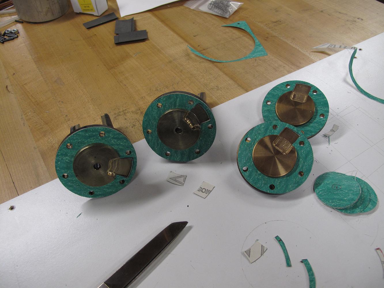
The cylinder gaskets ready for screw hole punching. We took an aluminum plate from an old hard drive which nearly had the correct ID, bored it out in the lathe…
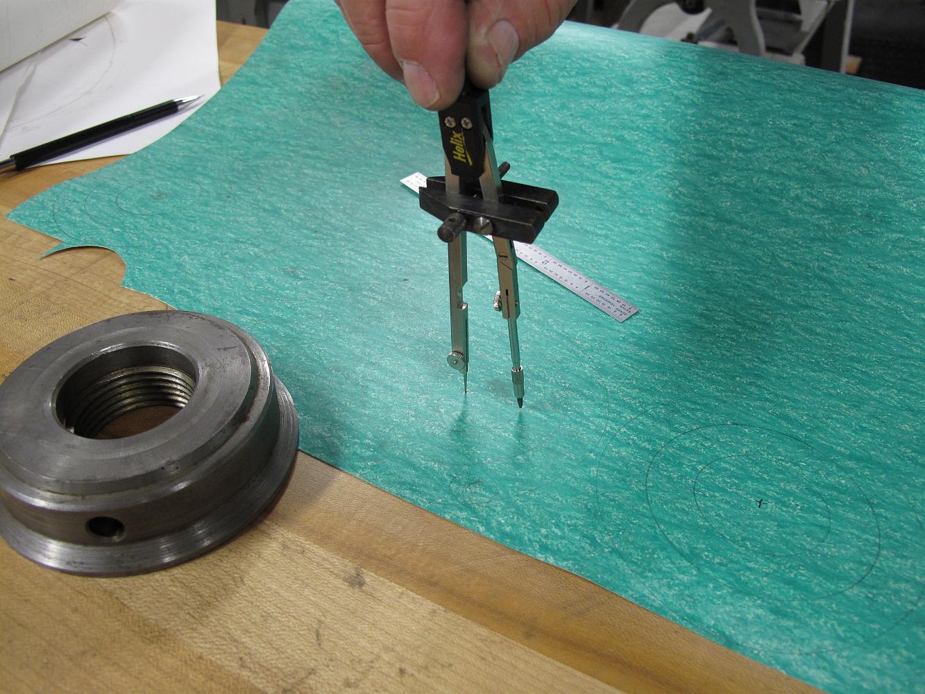
20-Oct-09 Using a divider to lay out the cylinder gaskets. I would have prefered to use a gasket cutter, but don't have one, so we will use the pencil and…
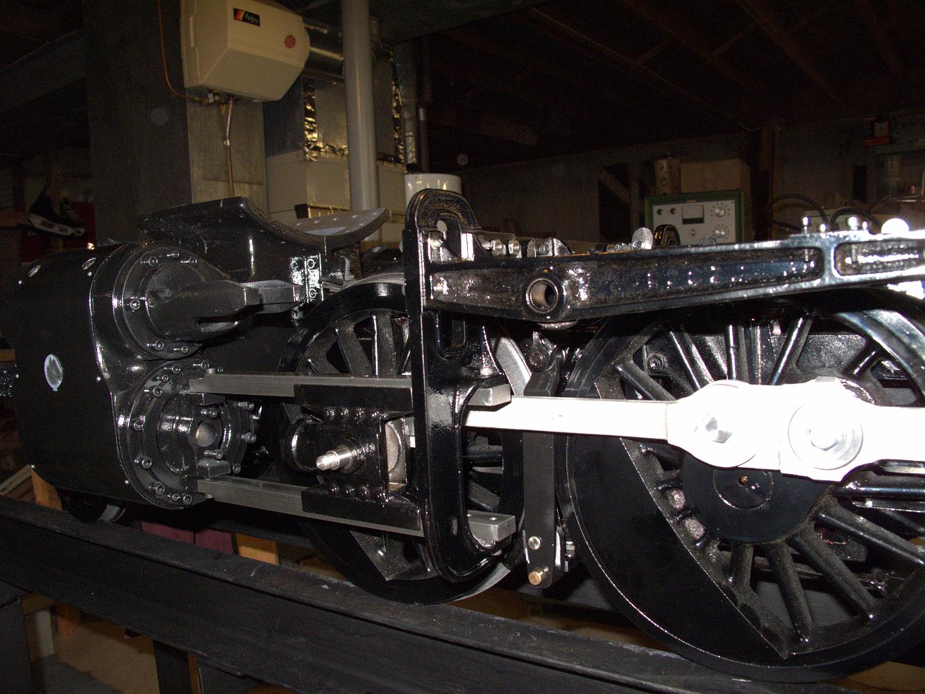
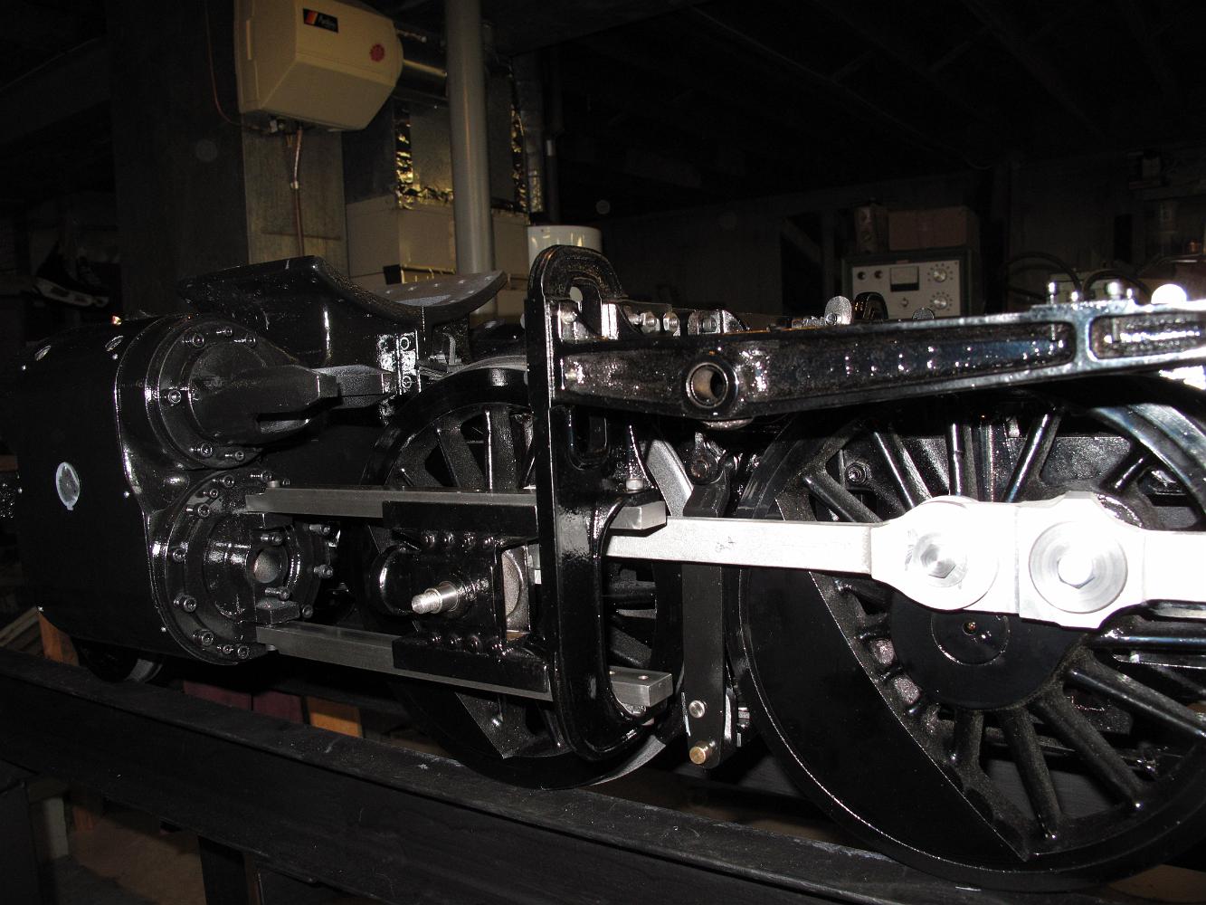
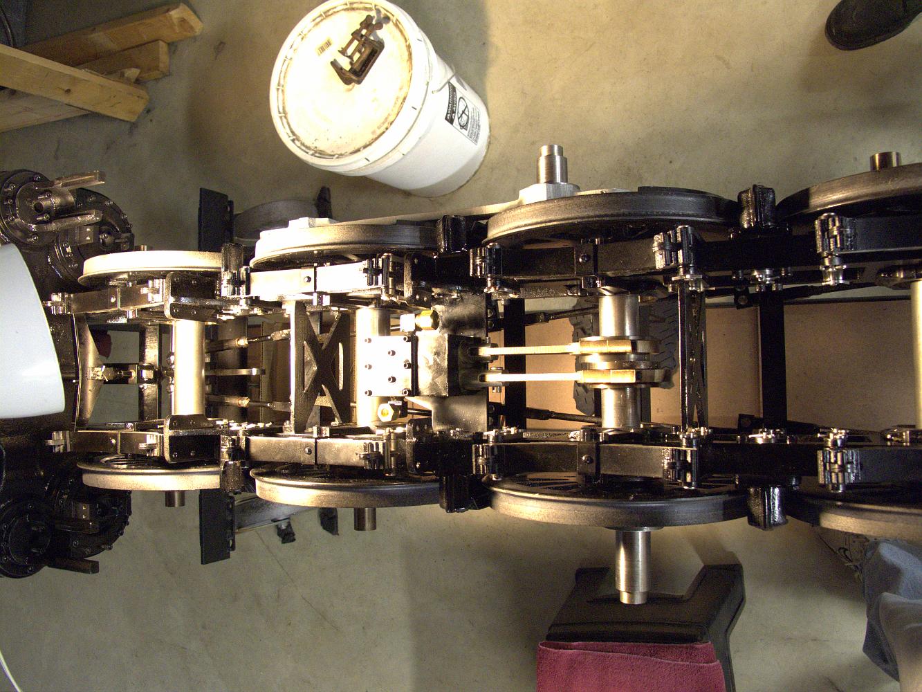
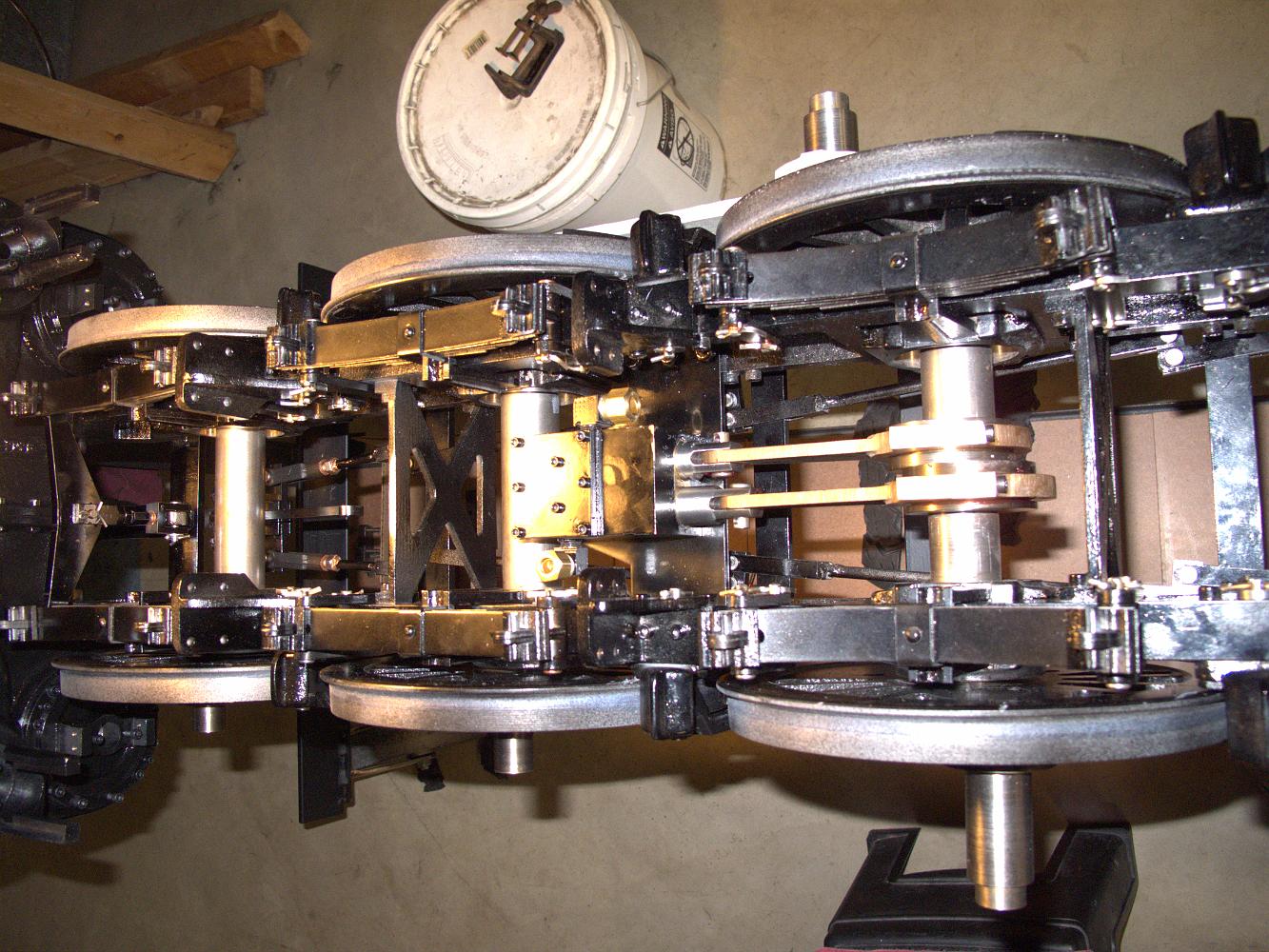
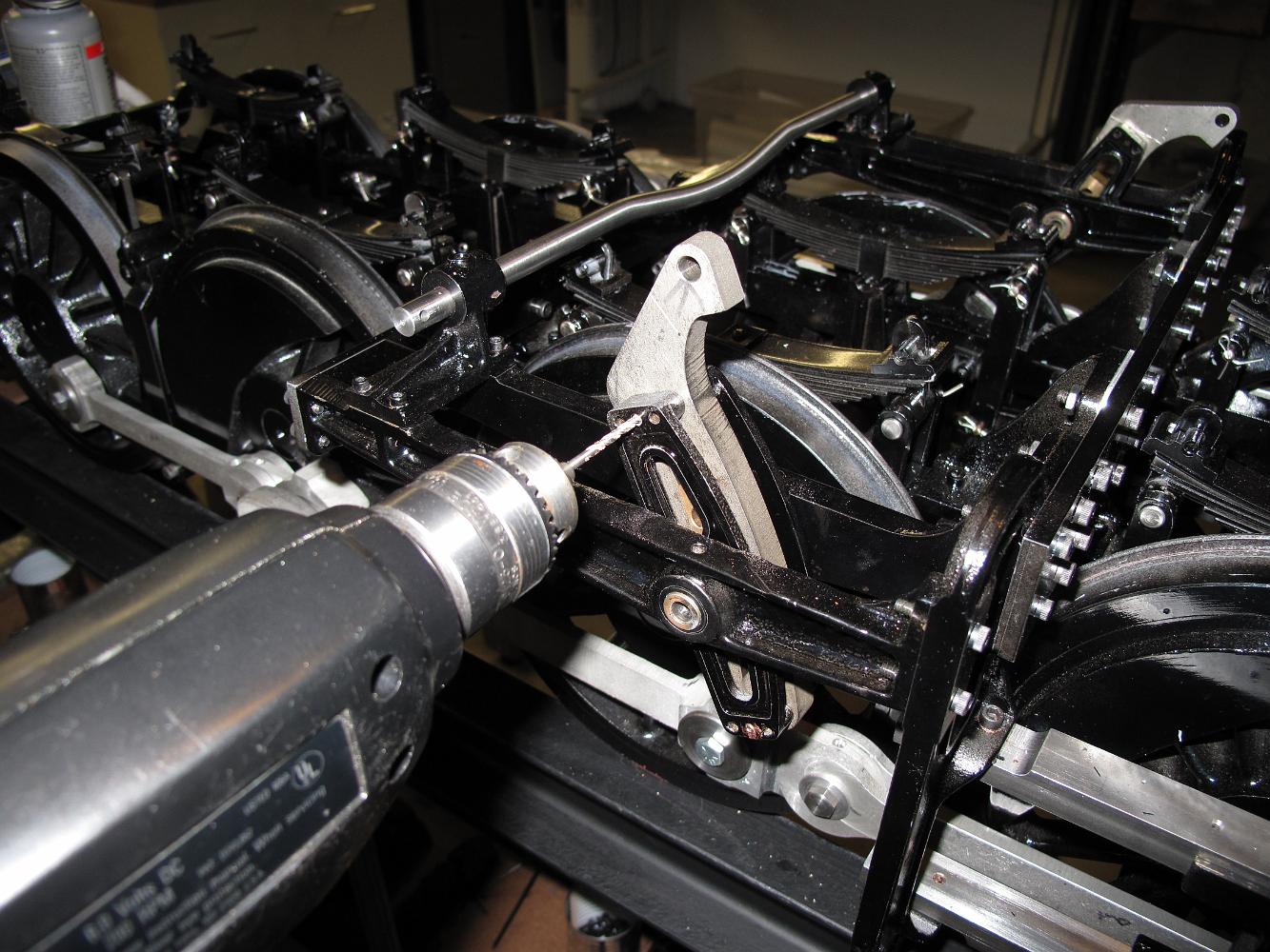
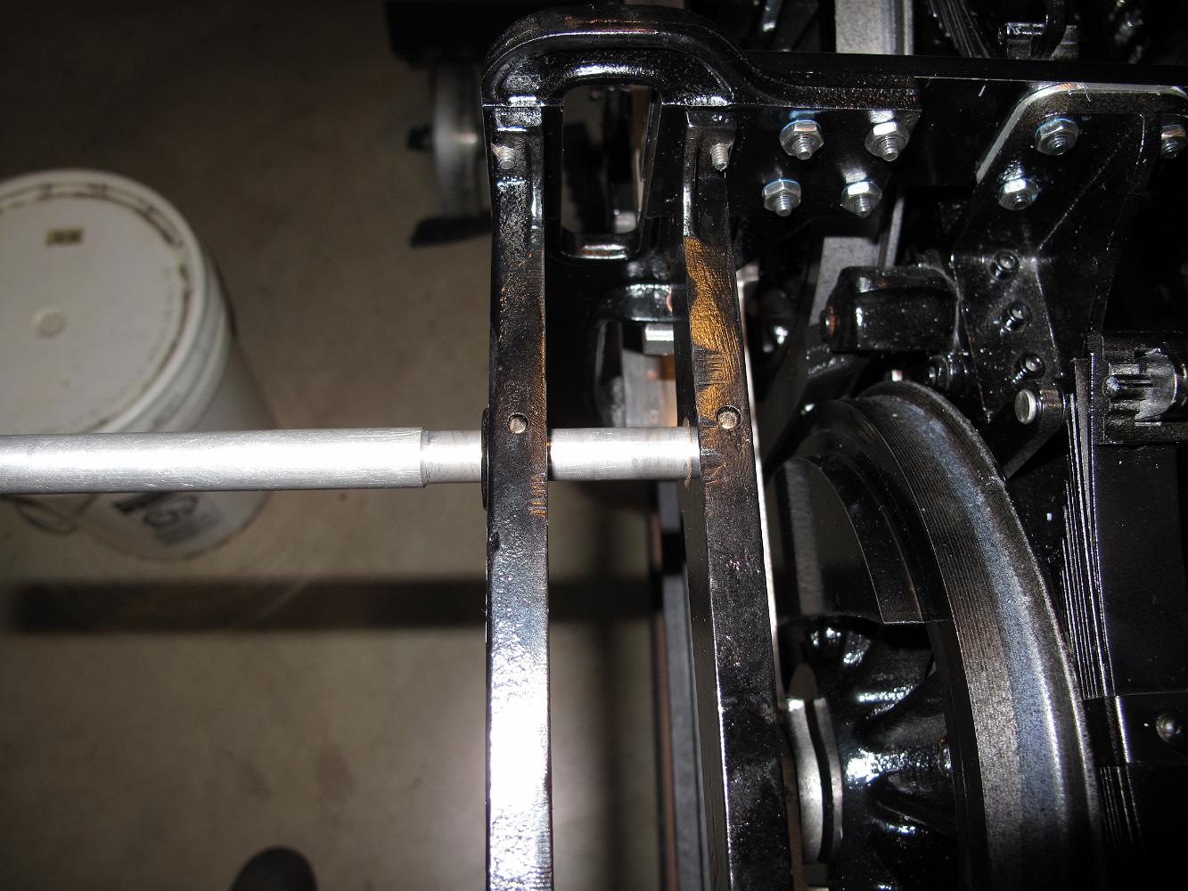
14-Oct-09 The motion structure temporarily in place. We need to shim the whole assembly .065 forward from the mounting brackets, but before we can do that we…
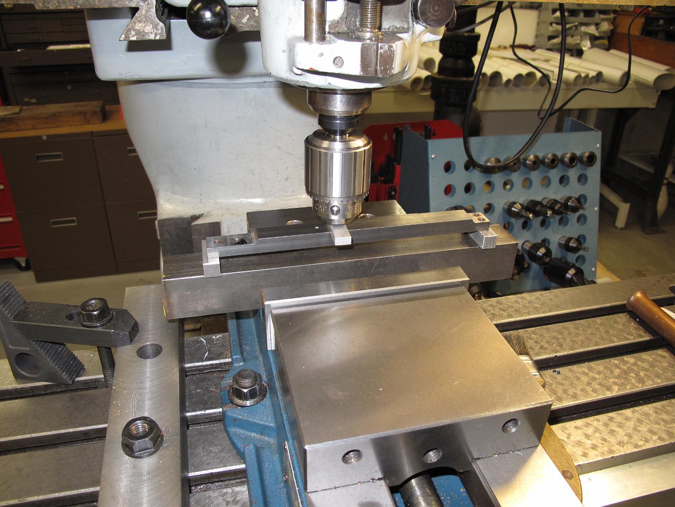
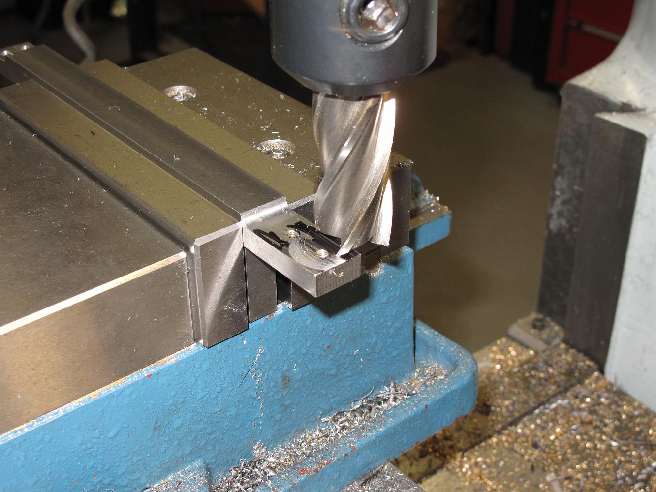
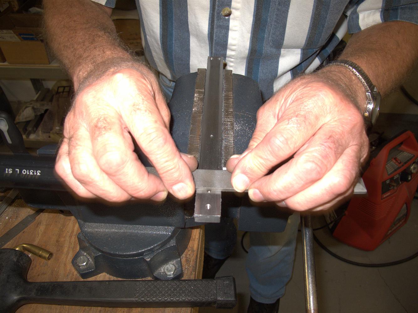
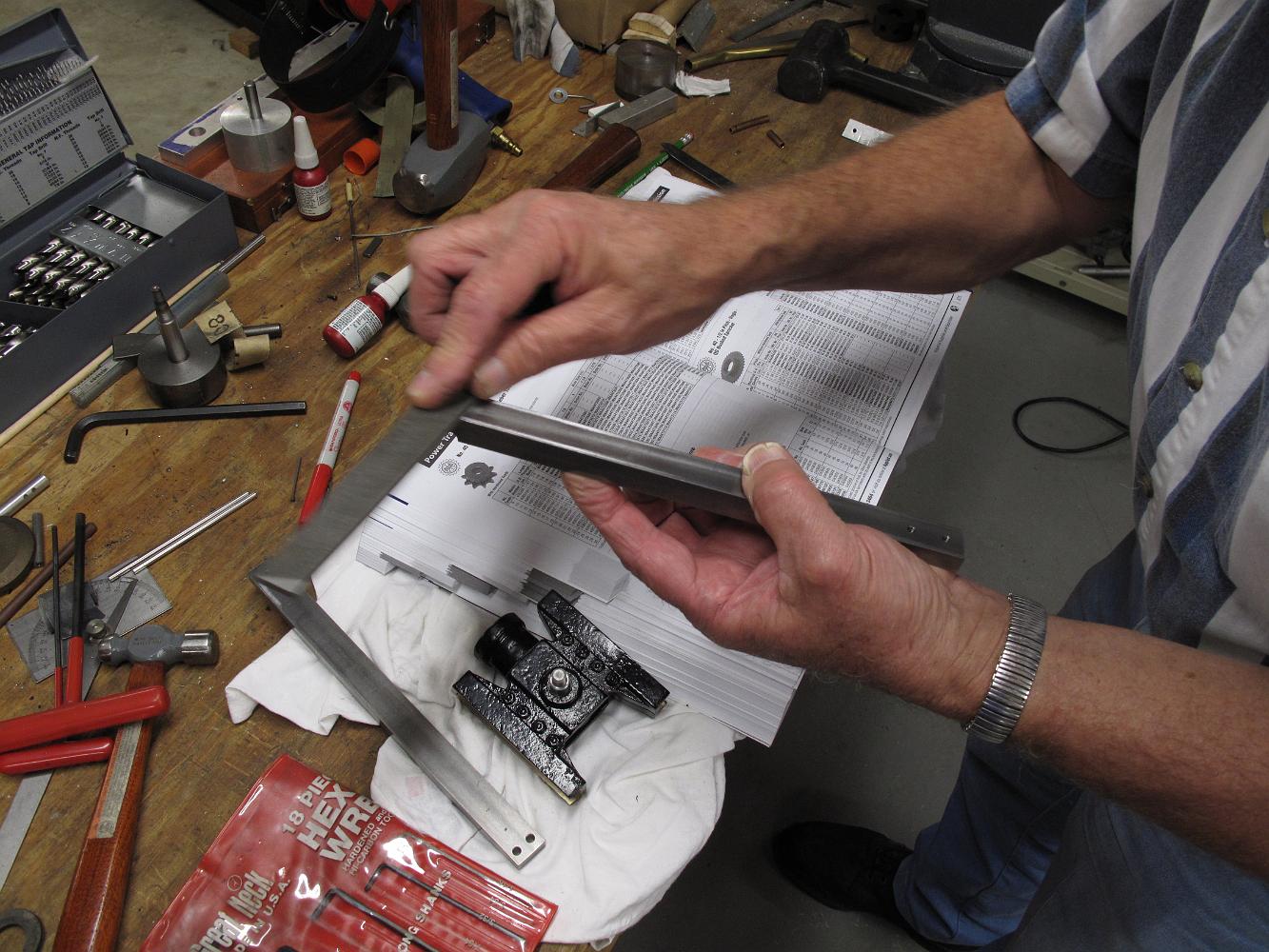
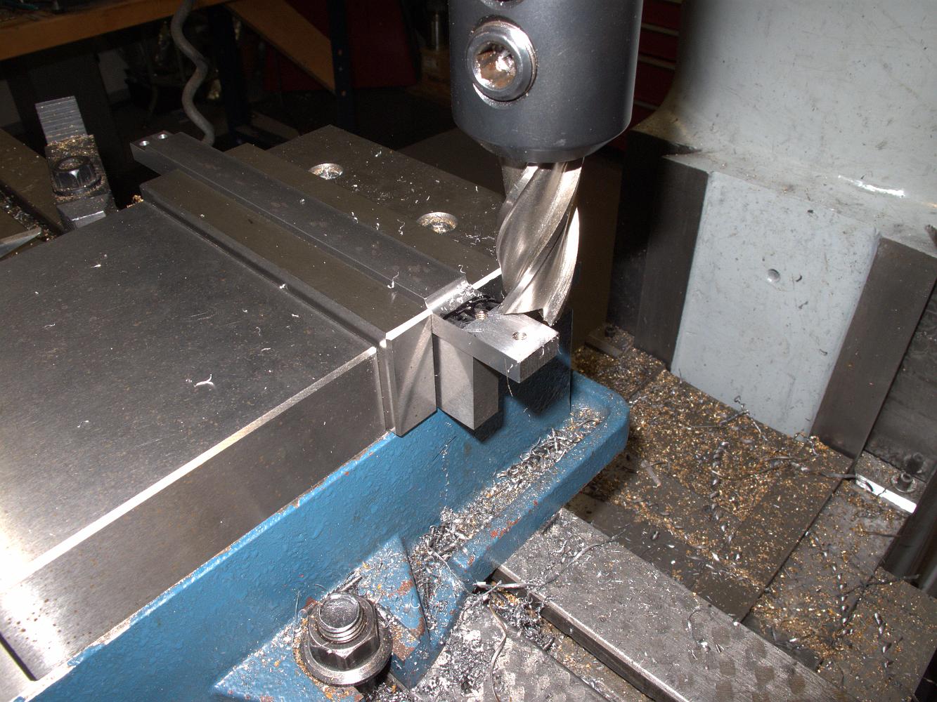
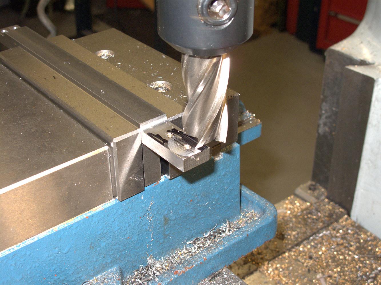
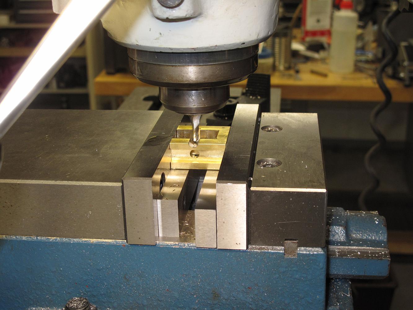
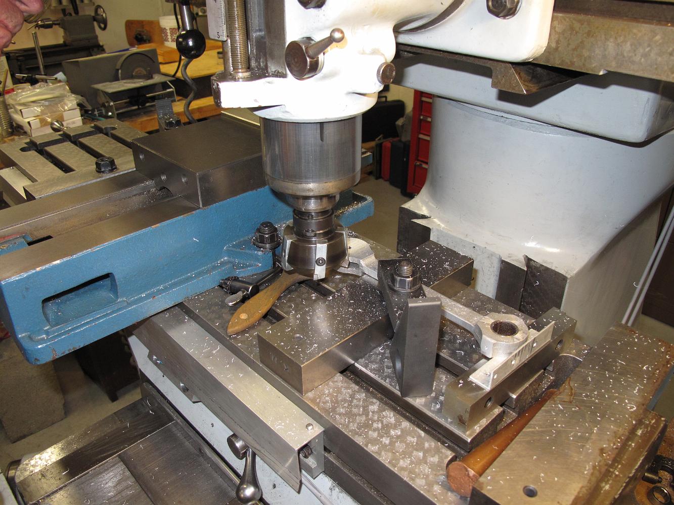
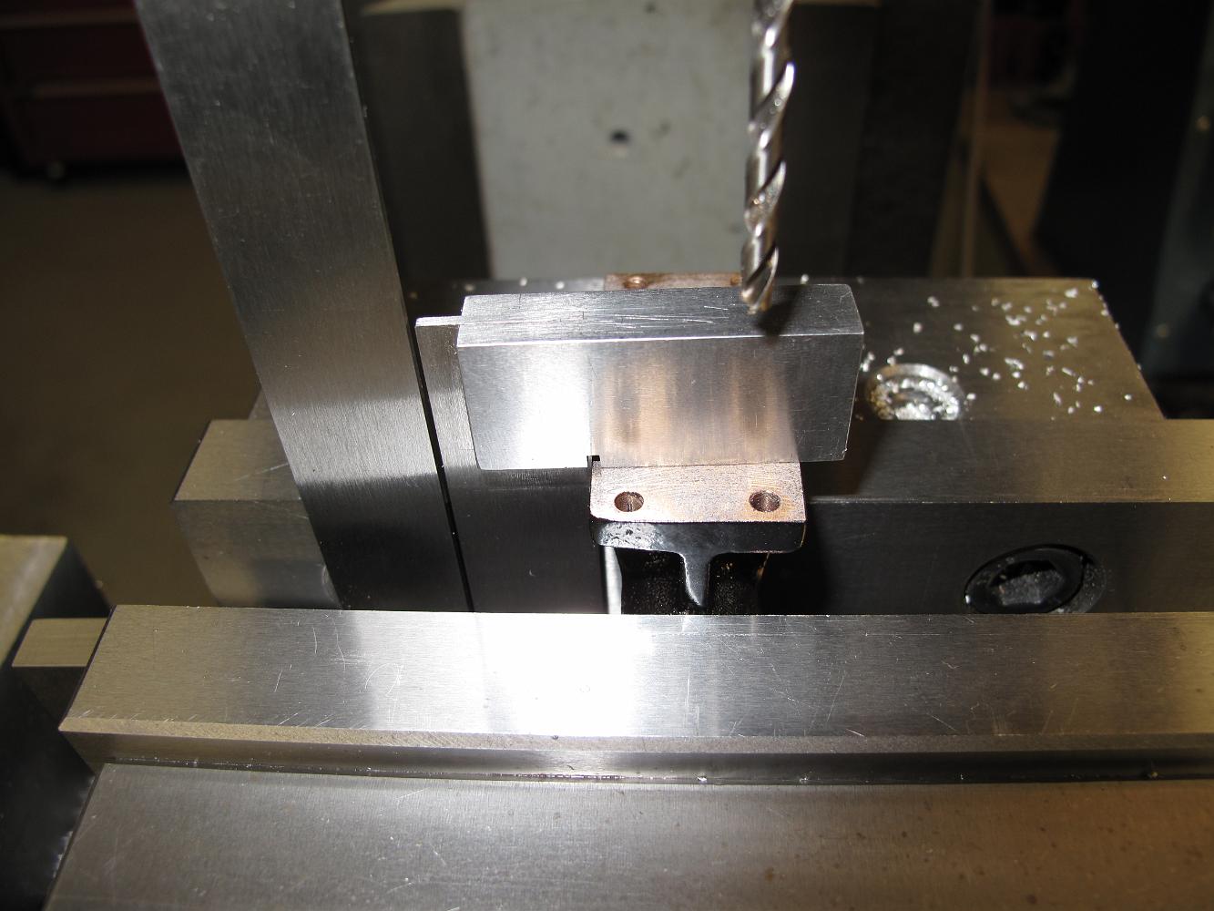
Machining the ends of the crosshead guide bars because the side milling operation left them tapered.
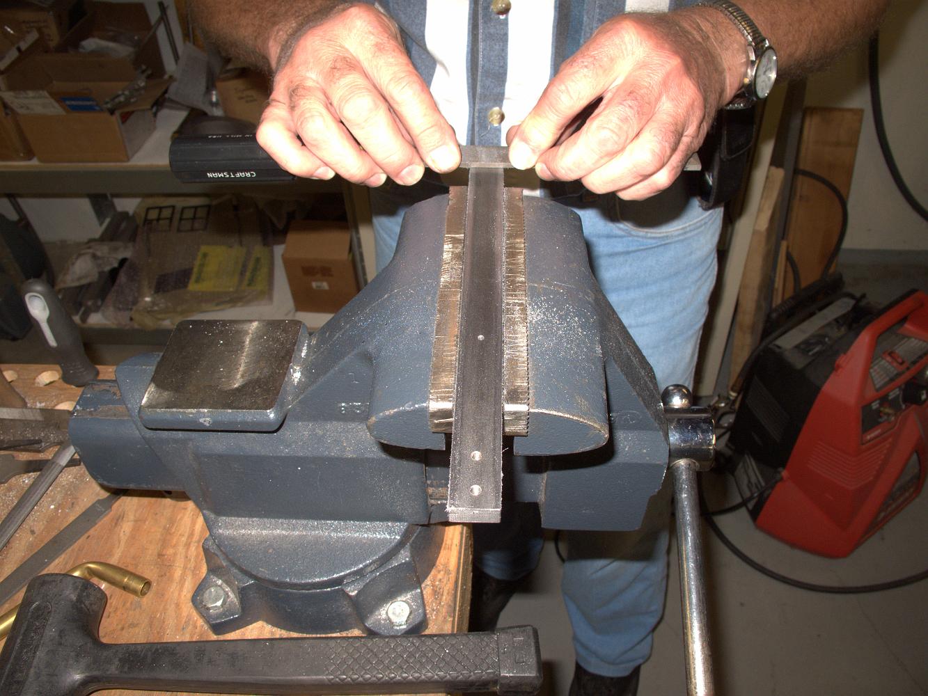
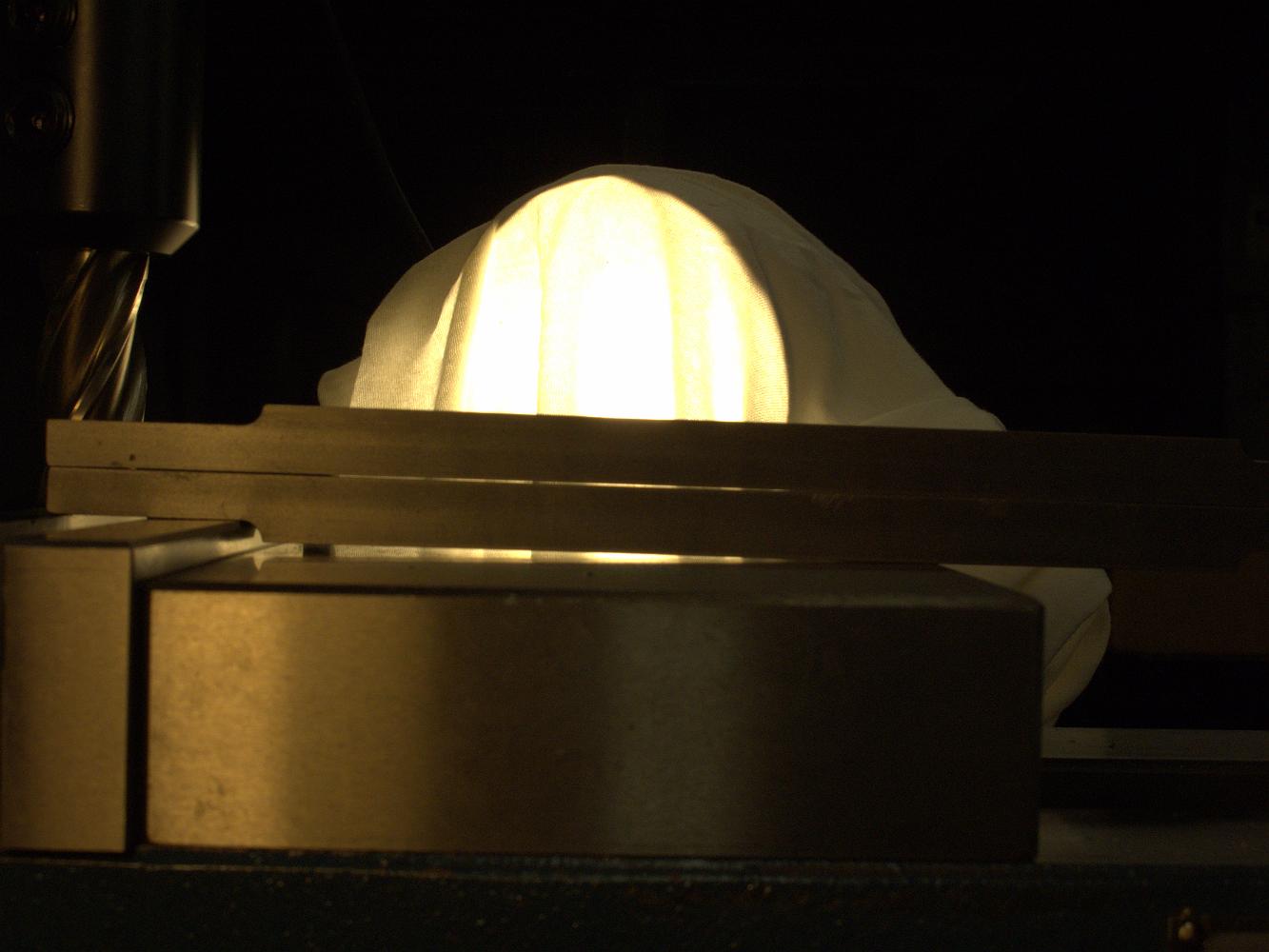
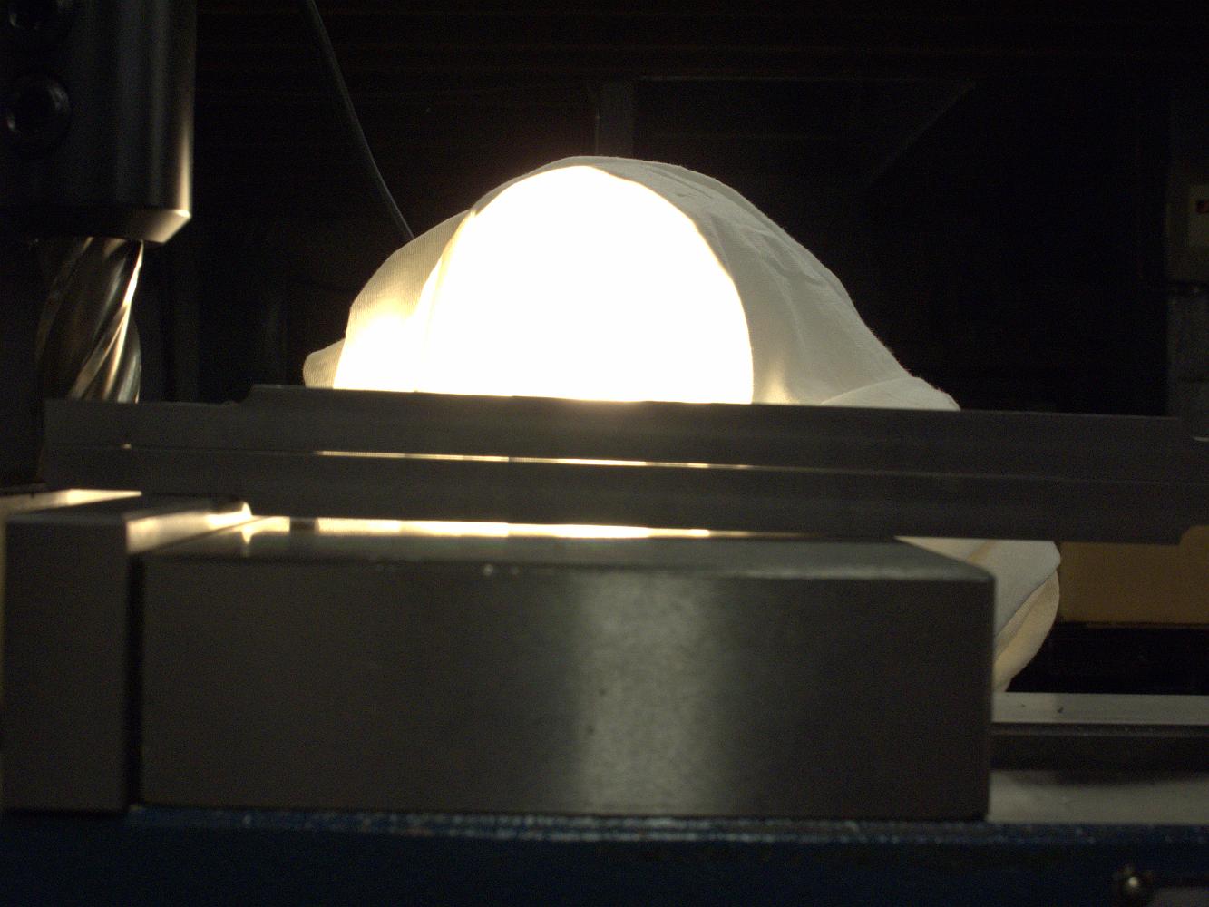
During the machining operation, inherent stress in the cold rolled metal is exposed. Here you can see the sliver of light between the two bars which have warped…
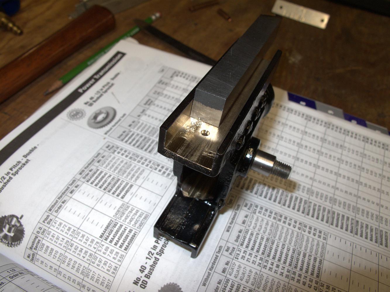
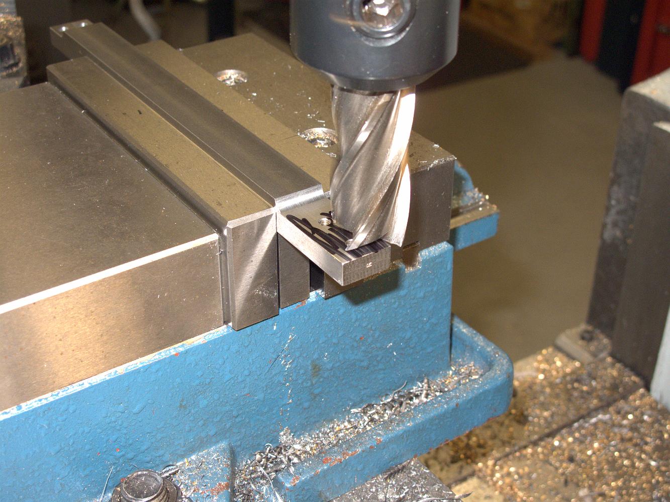
Our first attempt to machine the taper out of the crosshead guide bar ends. The black marker helps indicate the cut. We expected the cut to start at the end,…
During the motion structure assembly we were puzzled why things were not lining up, and why the crossheads would not go in between the cross head guides when…
While troubleshooting the crosshead assembly fit problem, we thought maybe the problem was the crossheads were not properly seating on the guide bar because of…
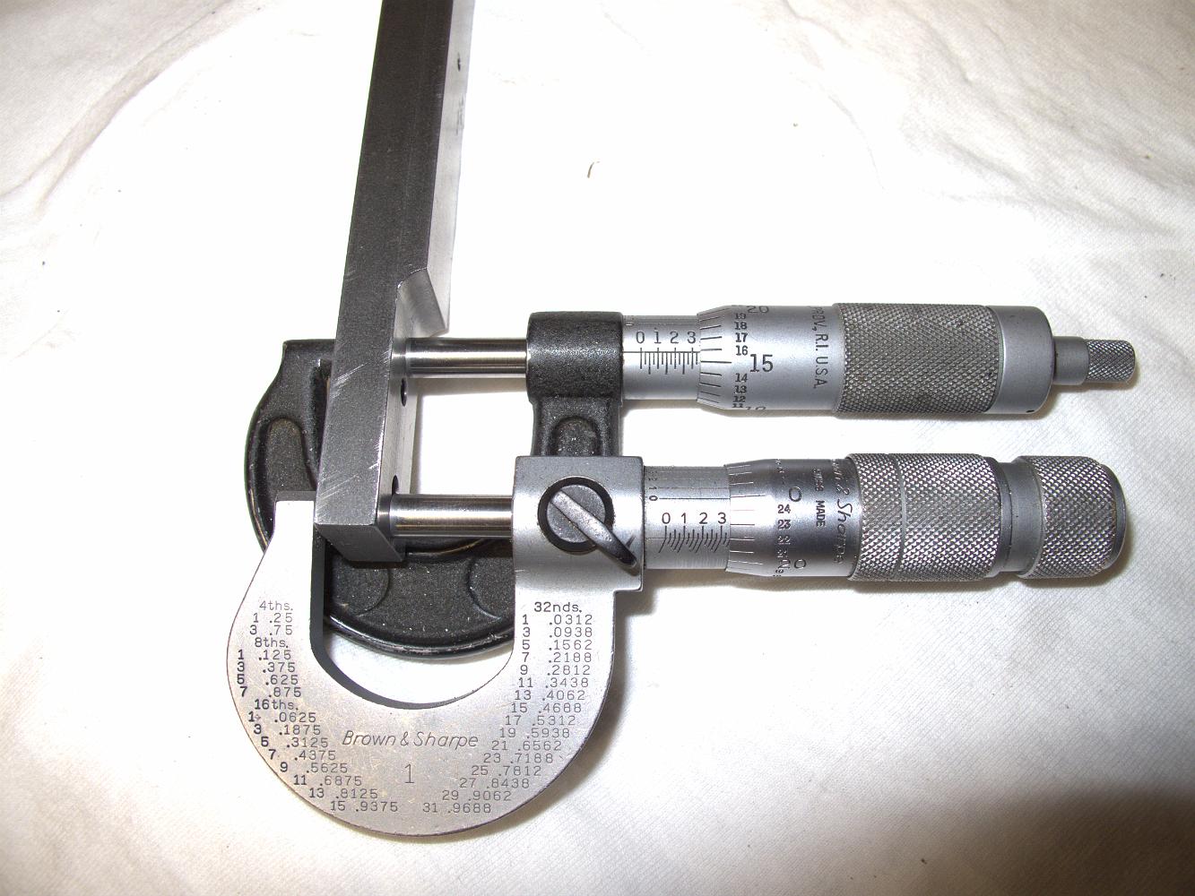
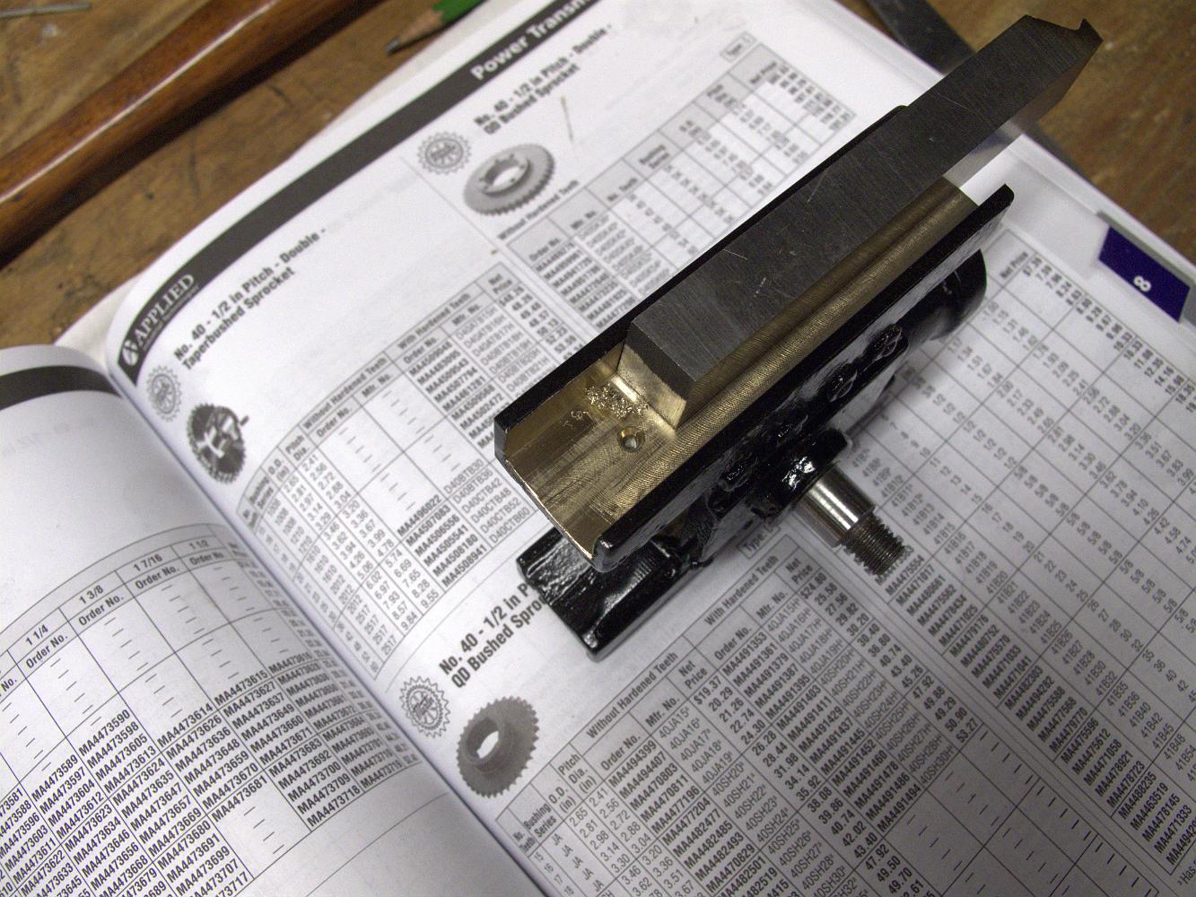
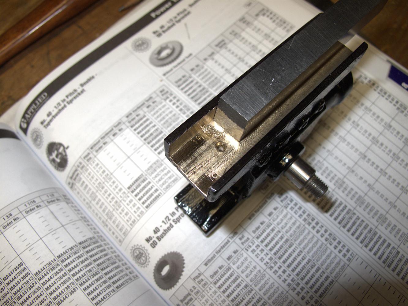
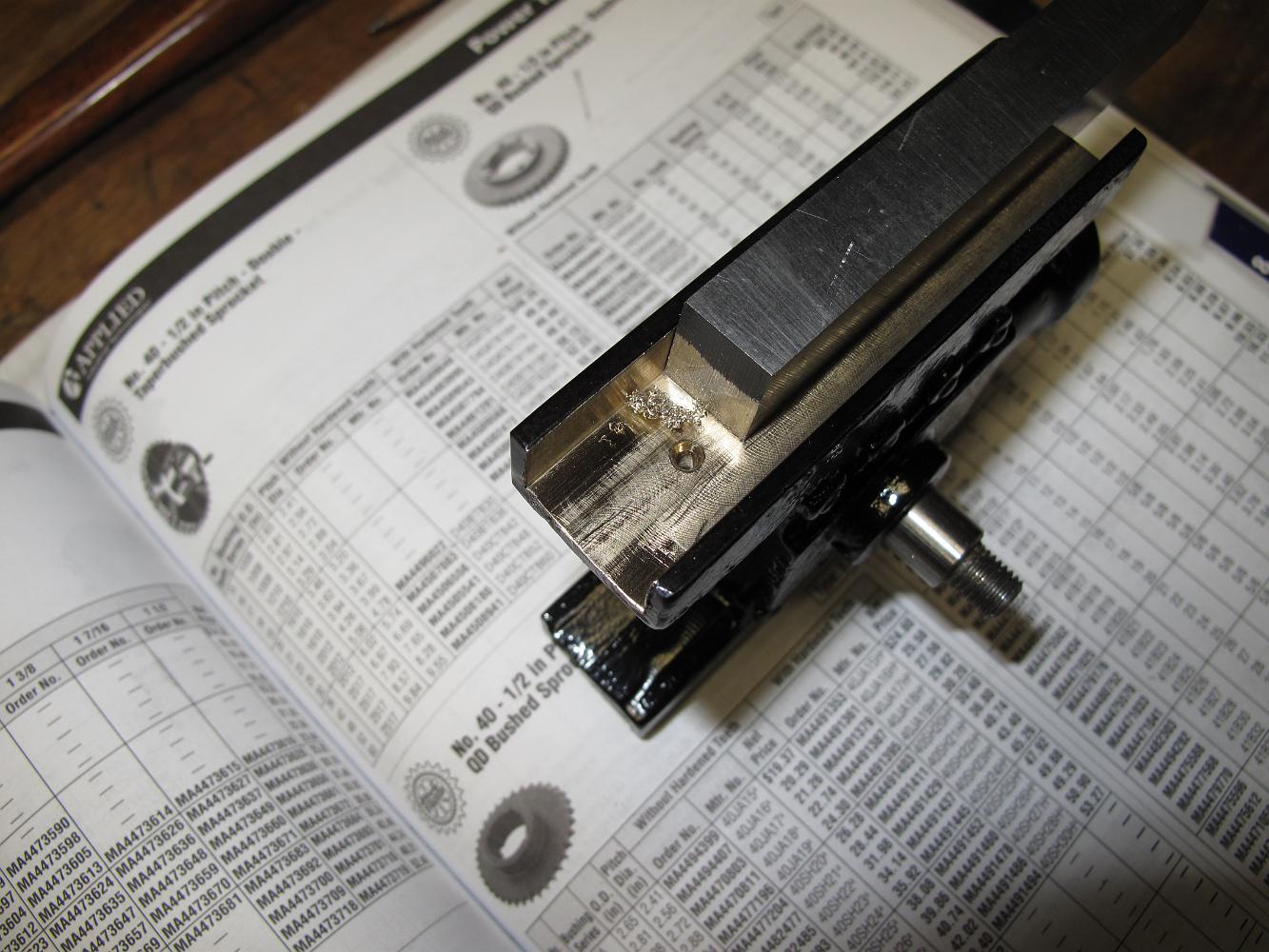
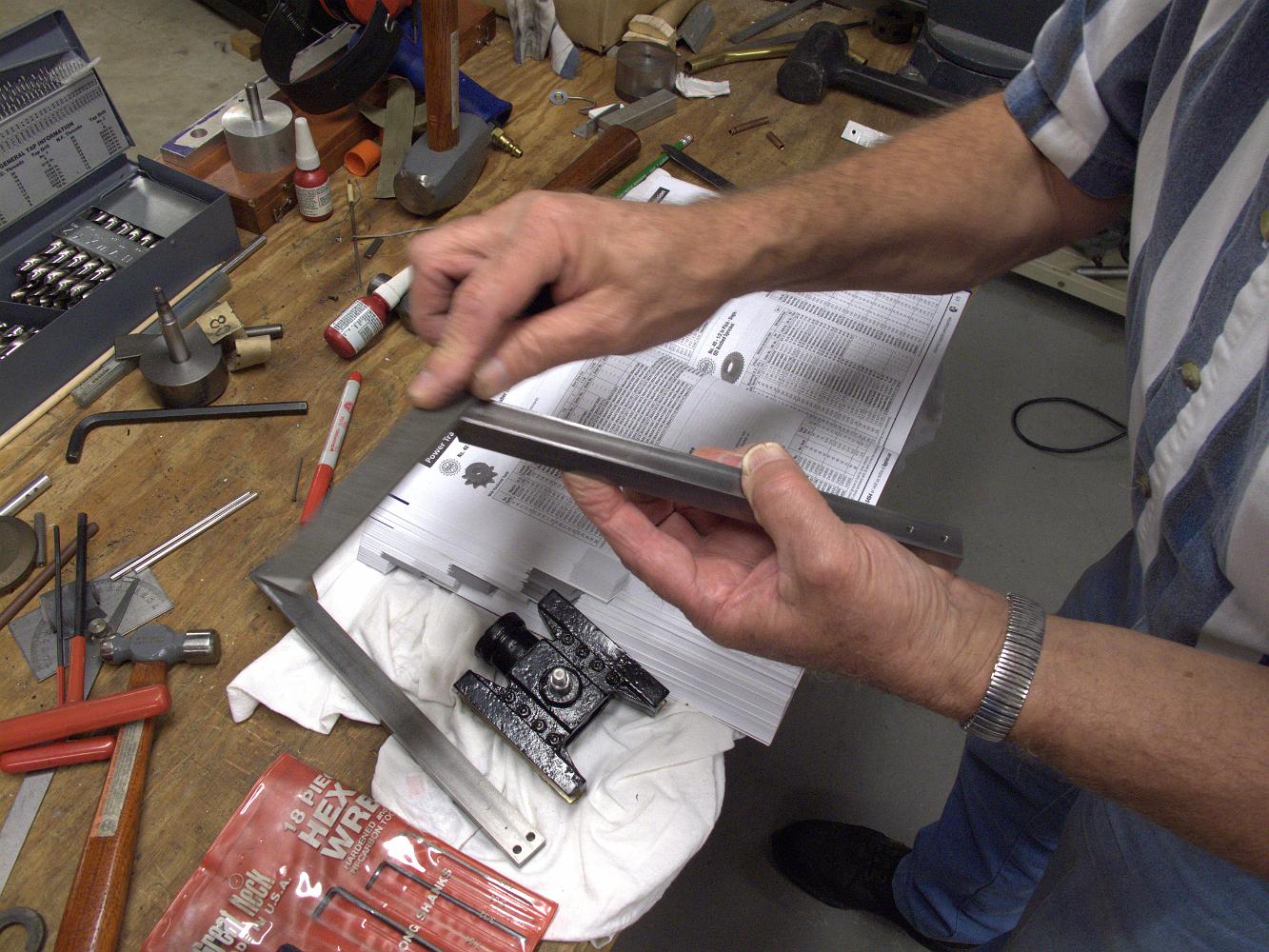
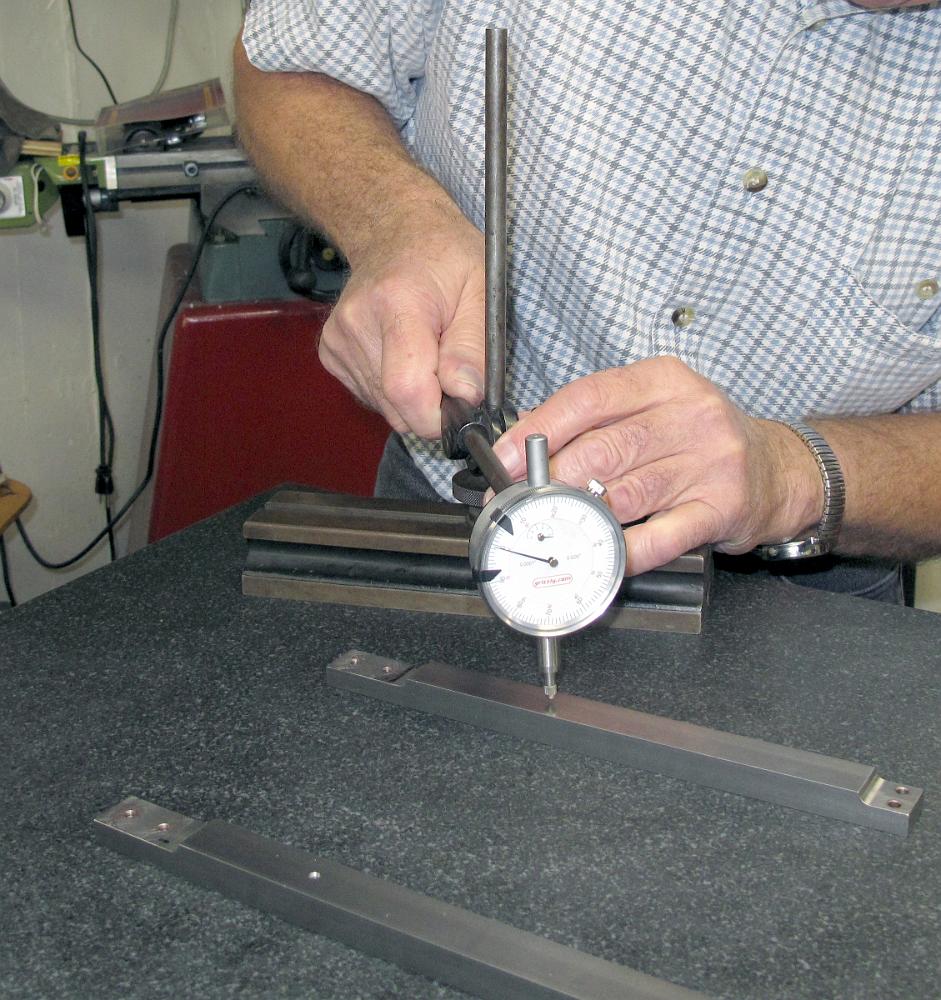
Draw filing the bearing surface of the crosshead guide bars. The file reveals the flat surface is actually cupped, with the corners high. Mic'ing the bar at the…
Another productive evening! The front truck was mounted and locked home, and the water pump and eccentrics installed.
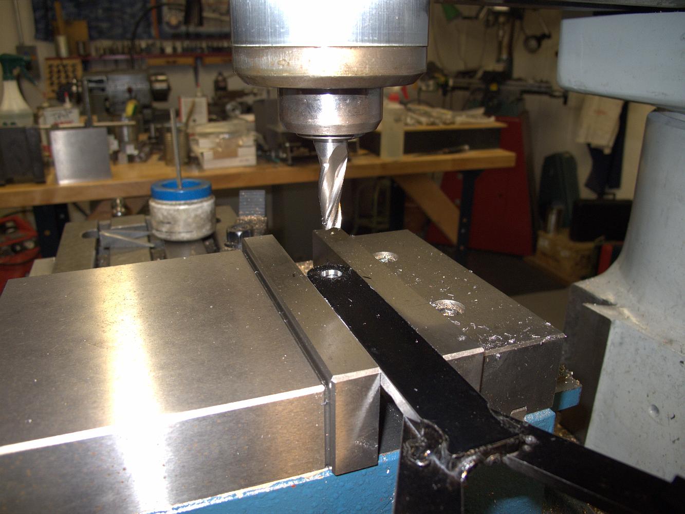
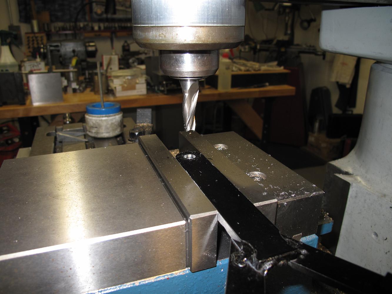
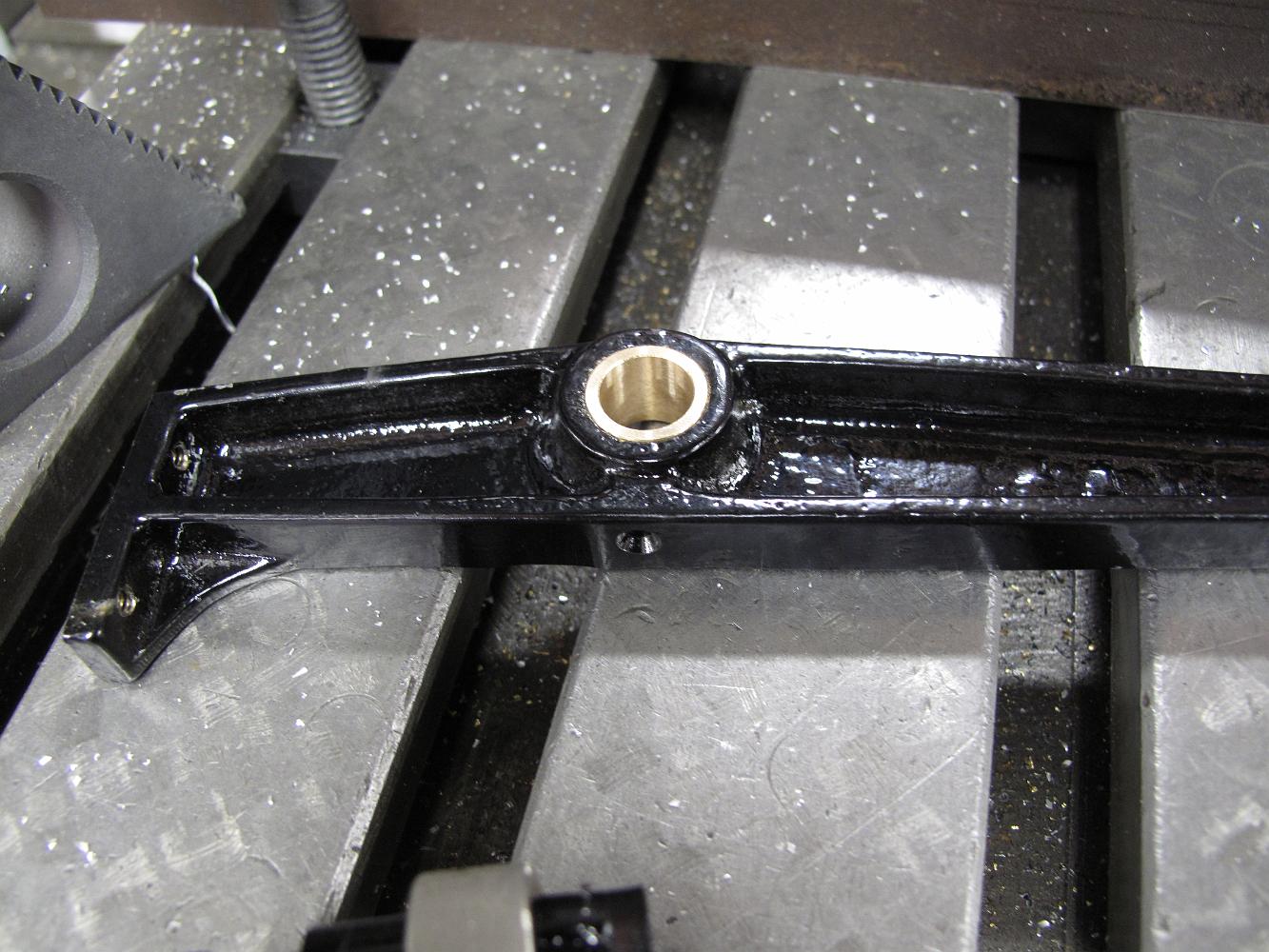
6-Oct-09 We make a minor change to the Pilot truck bracket -- using a 5 degree tapered endmill (we didn't have a 10 degree), we open the top and bottom of the…
25-Nov-09 After putting flats on the pins, we dry fit the rods we discover we cannot assemble things - there is not enough clearance in the half slot to put the…
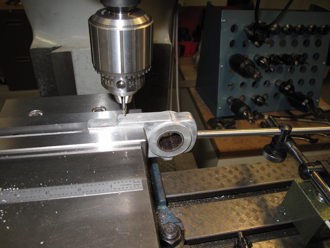
24-Nov-09 Drilling the holes for the roll pins one more drill size larger. The 3/32" holes were just too small for the roll pins, completely closing them up…
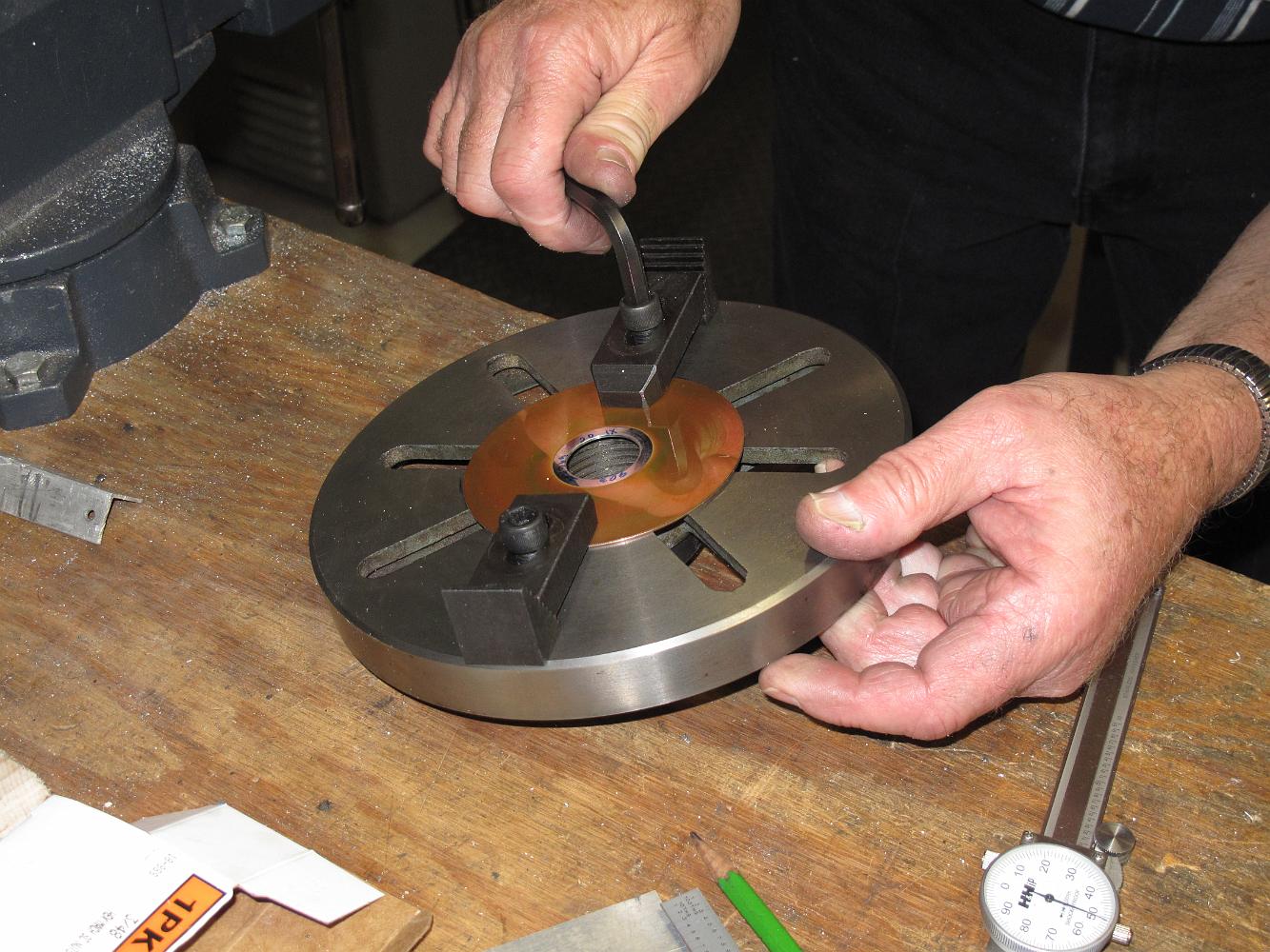
What do you do with your old computers hard drives? I take mine apart and keep the polished aluminum disks for scrap parts. Here Bill is bolting one to the…
18-Nov-09 After assembly we saw the front and rear rods ends were a paint thickness away from striking the brake hangers. We know things will loosen up as the…
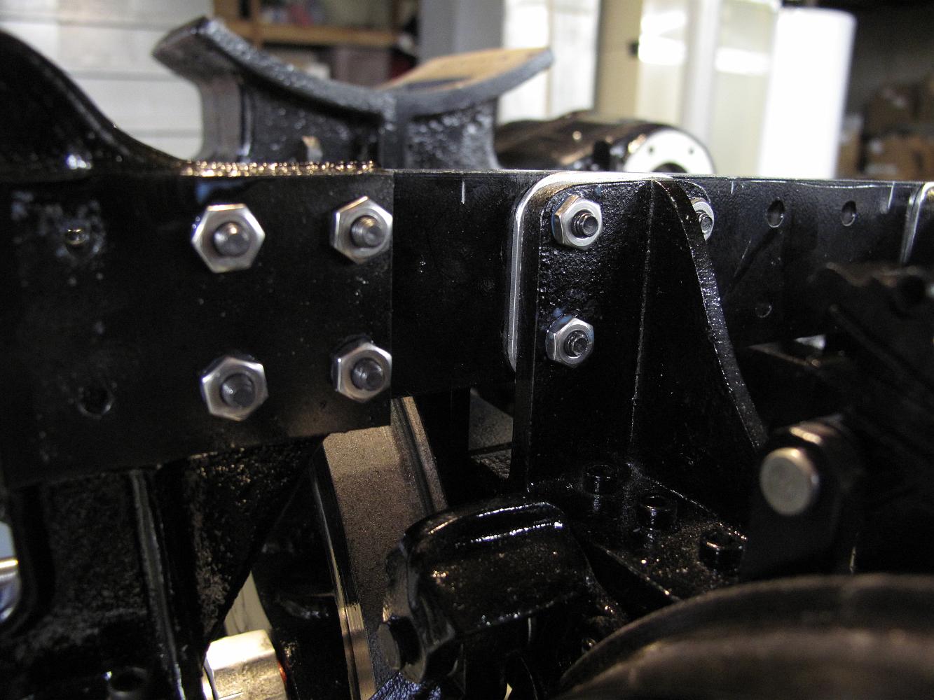
3-Nov-09 After an evening of making the Support Bracket shims, we proceed to position the Link Support Arms to their final position. With the bolts tightened…
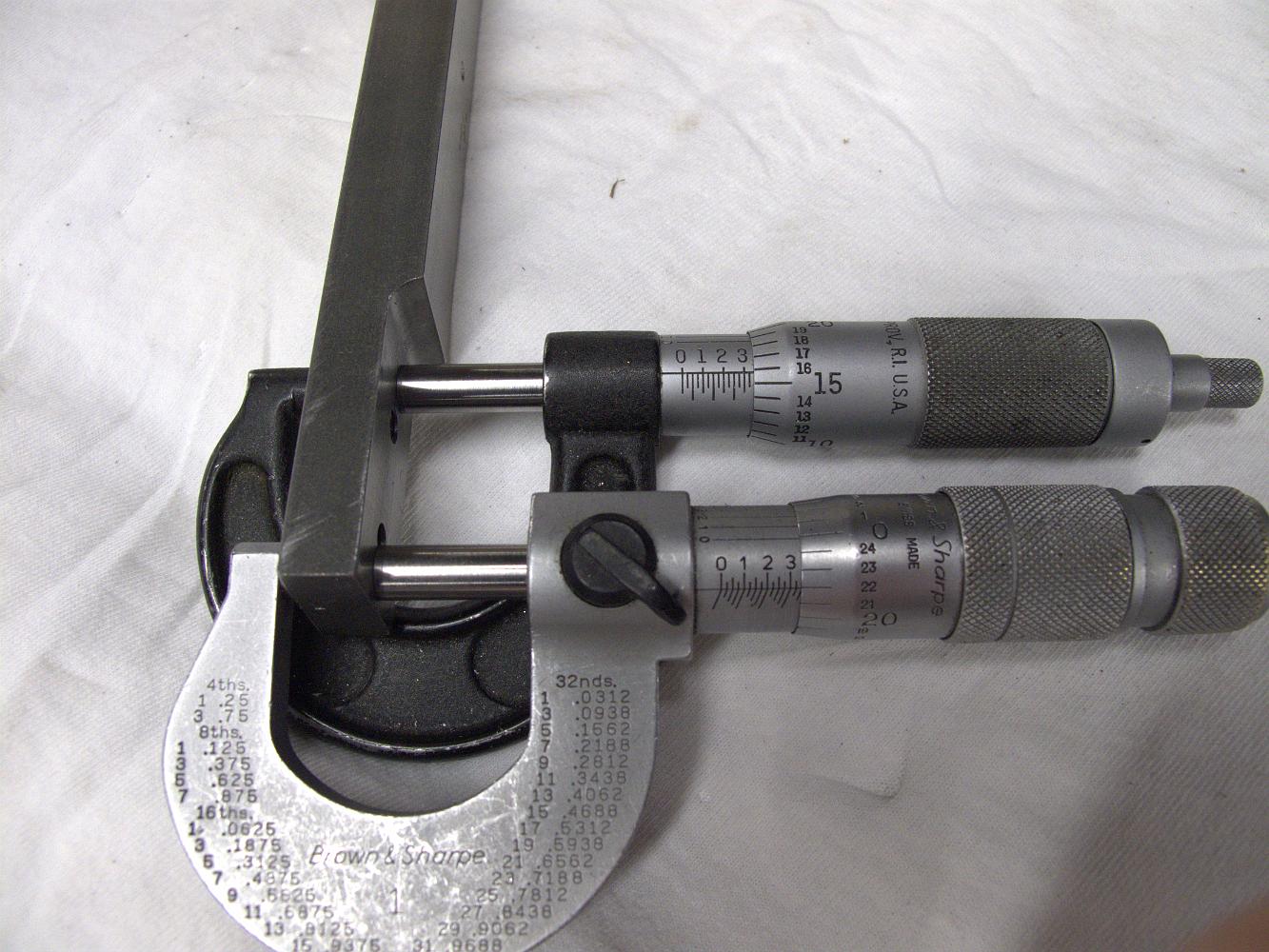
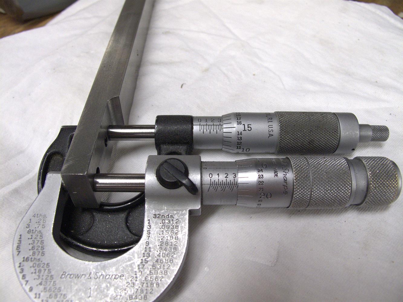
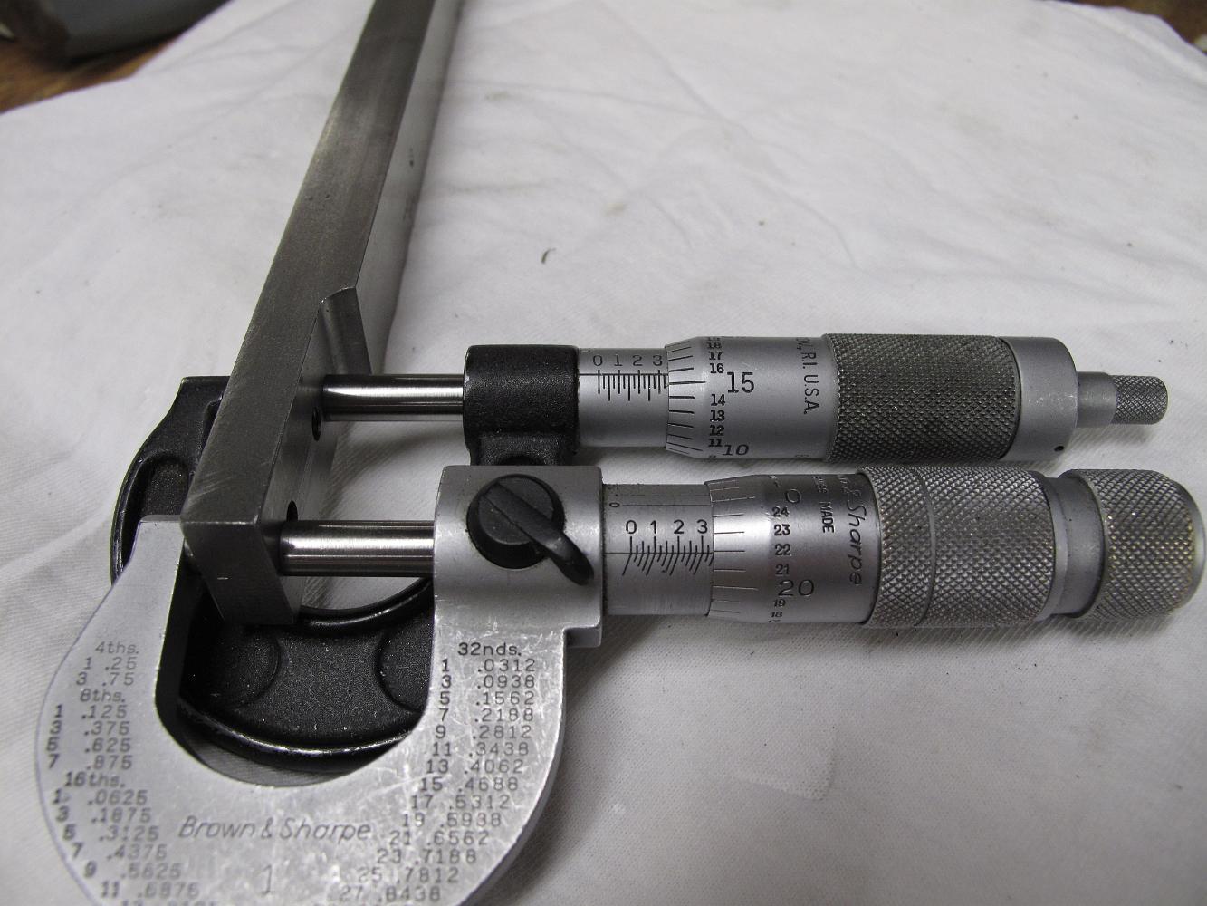
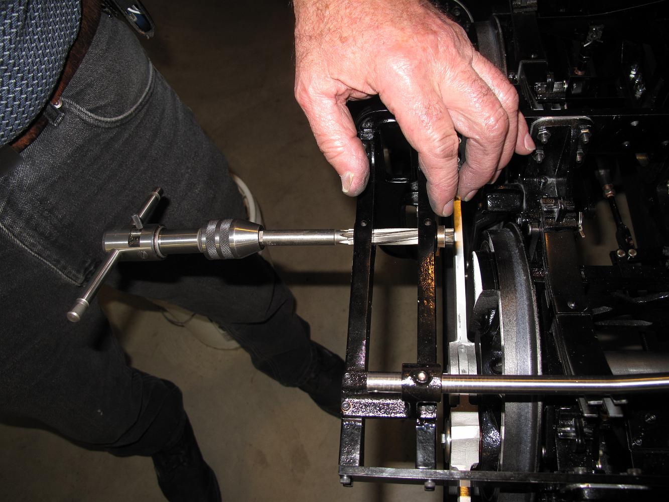
28-Oct-09 Using a 1940's Brown & Sharpe Test Set, which I just learned how to use, Bill takes measurements on the crosshead guide bars to find out why the…
While Bill was working on the bushings, I enlarge the Tumbler Shaft Pillow Block mounting holes by one drill size. With the original close fitting holes the…
11-Nov-09 Using a piece of aluminum to rough align the Brackets while loosely bolted. Then we tighten the bracket bolts and line ream the bushings to size and…
While aligning and reaming the Link Support bushings, yet another bushing broke loose and spun out, so we had to make another new one. We think the Telescoping…
11-Nov Here you can see the outline of the .060 thou aluminum shim we had to put between the link support bracket and link support bars. I'm using socket head…
Problem found! The fireman's side valve crosshead guide does not have enough travel in it--the crosshead jams against the cast wall. Not wanting to tear the…
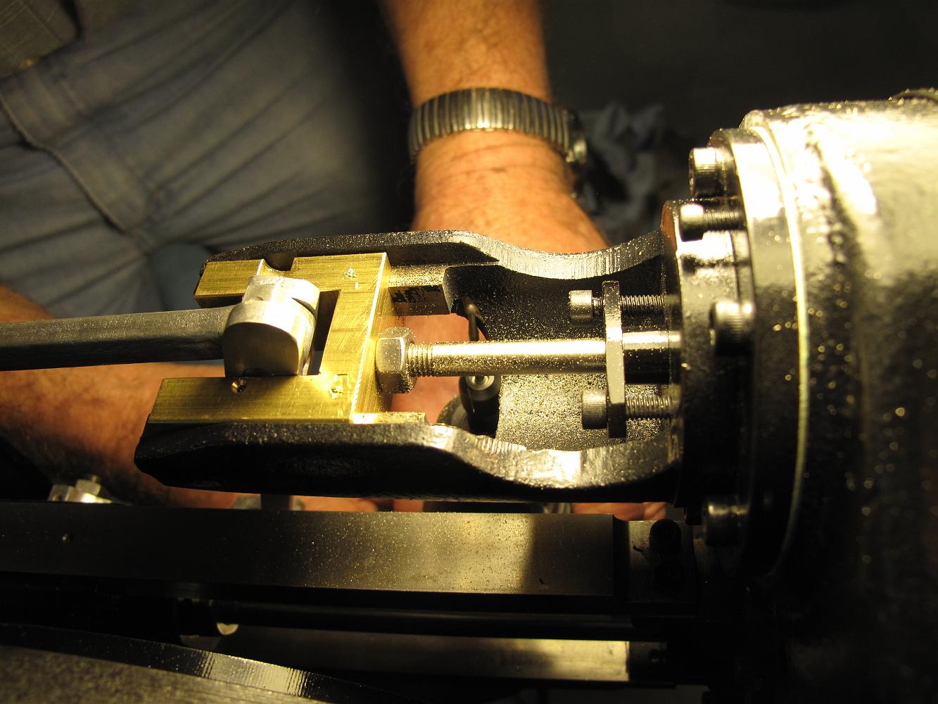
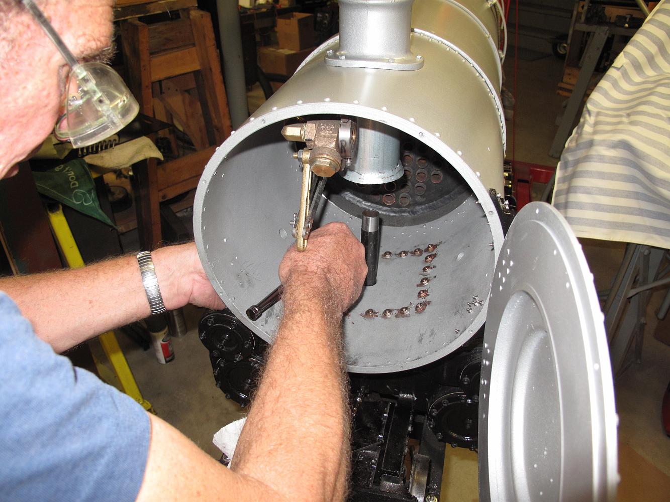
The Valve spools have been centered in the valve cylinder using the inspection holes in the cylinders. Locking the tumbling shaft down with machinist clamps, we…
9-Dec-09 Tonight, the last shop night of the year before I take holiday for three weeks, we begin timing the engine. We block the axle boxes up with 1/4" square…
5-Dec-09 Another five hours of work today and all the valve motion is installed! Bill worked on one of the valve crosshead guides to make sure it moved without…
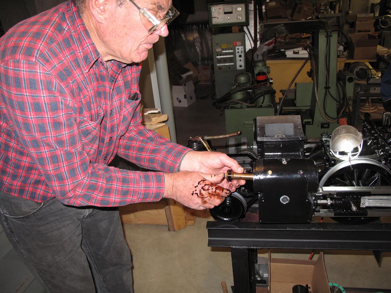
Chocolate syrup on the hands? No just old fashioned steam oil which has been spread on the piston and valve cylinder walls, also worked into the cast iron rings…
5-Dec-09 It's a Saturday and 20 degrees outside. I decide to work in the shop instead of out at the track today, along with Bill. We have tightened the piston…
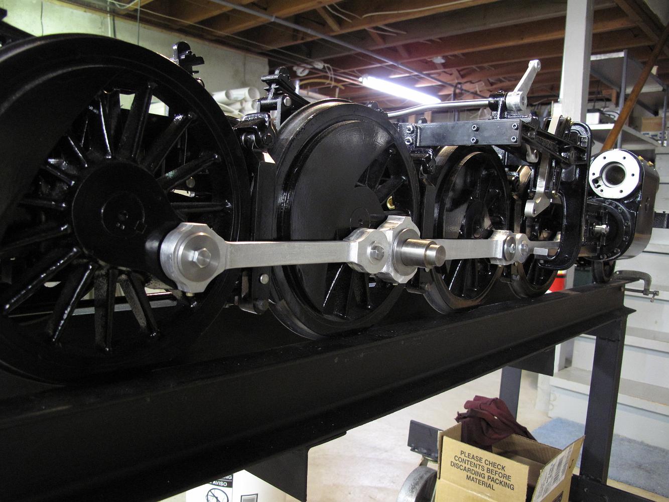
2-Dec-09 At the end of the night, all the rods are installed on the engine. Things are starting to move when the chassis is rolled!
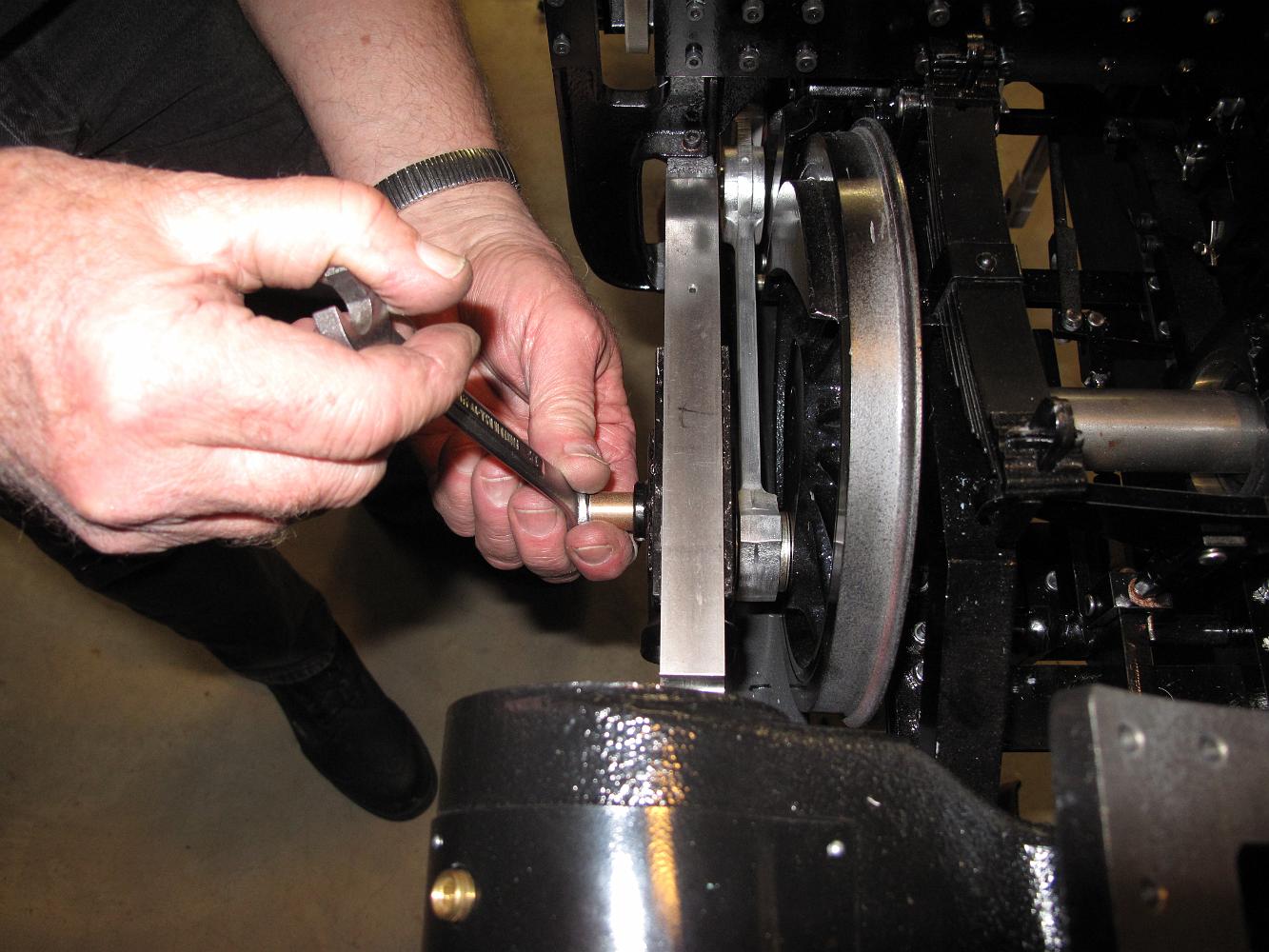
Bill uses a bushing to pull the crosshead pin out of the crosshead. There was a slight burr from drilling the roll pin hole which made it hard to pull out. We…
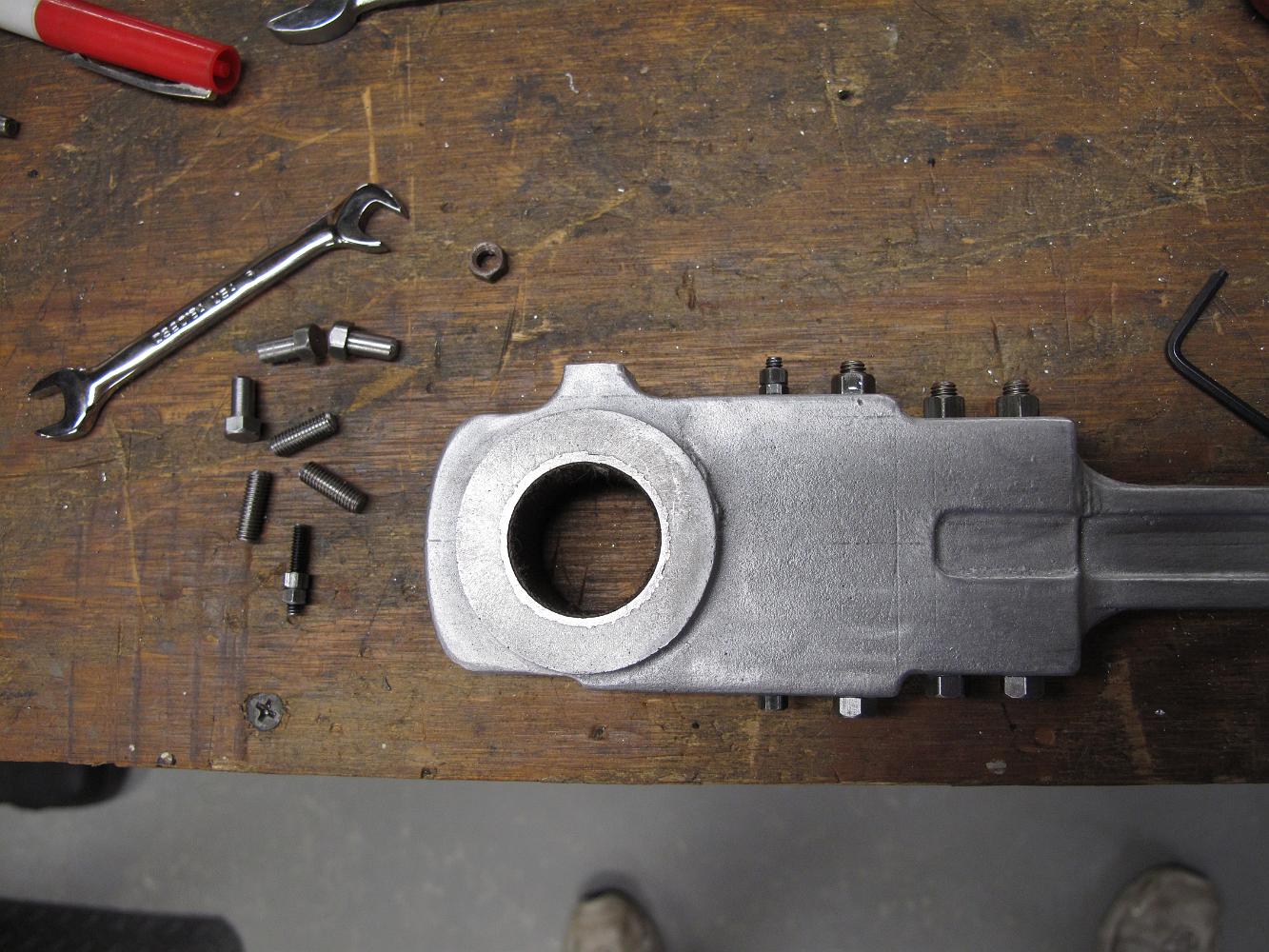
The rods have been sandblasted, thanks to the use of a benchtop blaster from Tim M. I then used an abrasive finishing wheel (like a gritty sponge) on my Dremel…
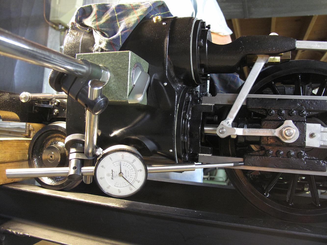
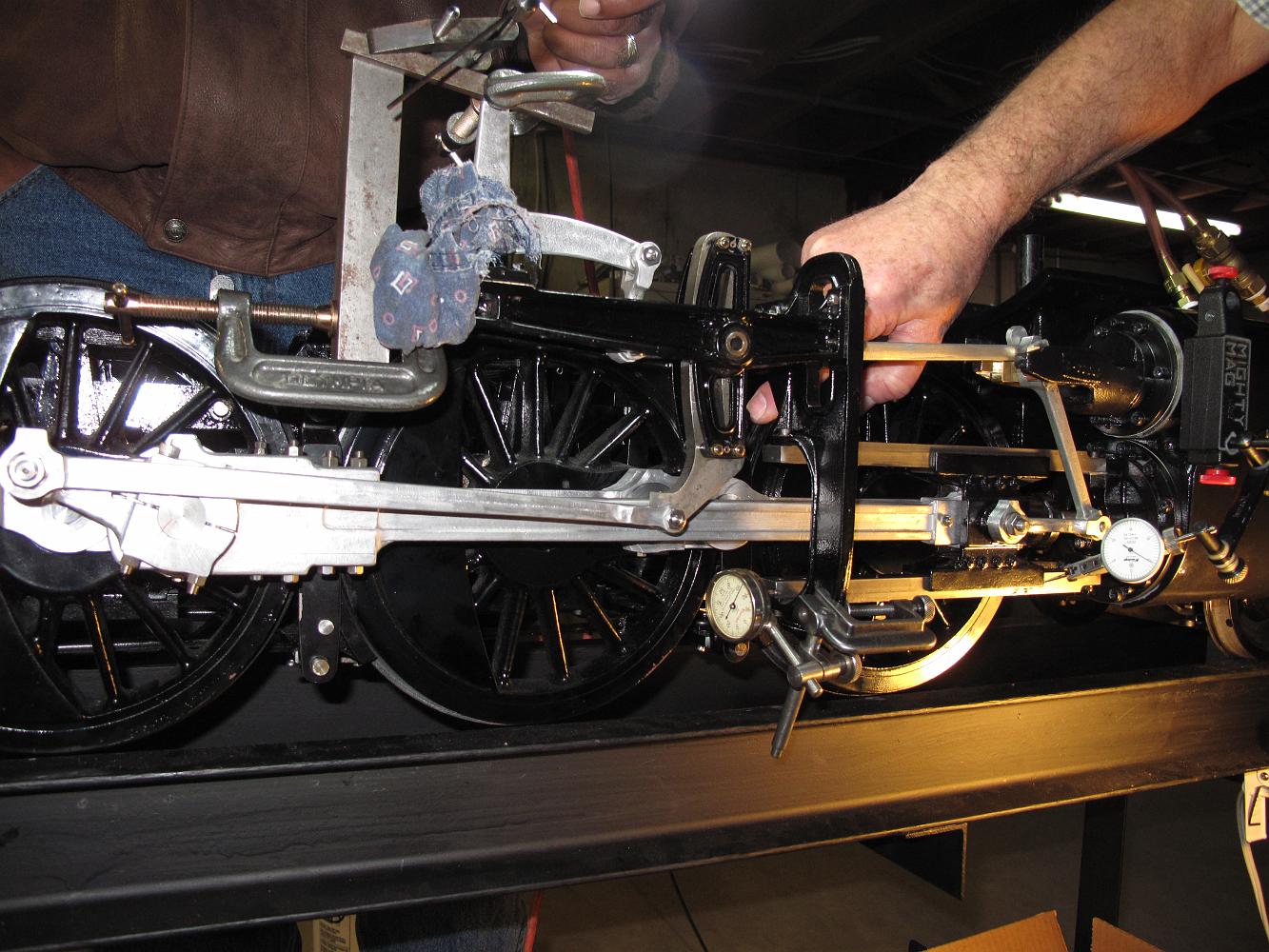
9-Jan-2010 Timing the engine. Using dual dial indicators on the front and rear of the crosshead guide bar, we are confident we know when front dead center and…
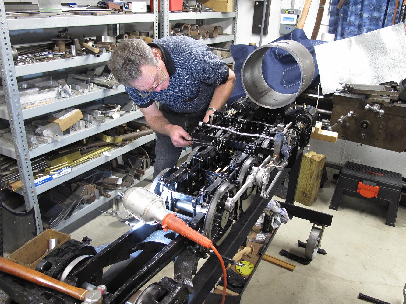
24-Feb-10 Fine-tuning the engine chassis. Based on Charlie Docksiders valve motion computer simulator, Bill makes some small adjustments to fine-tune the…
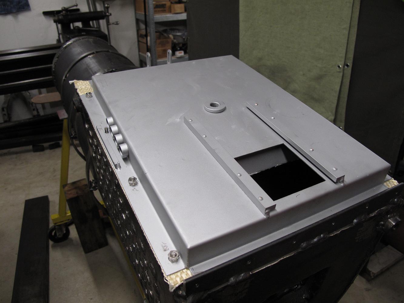
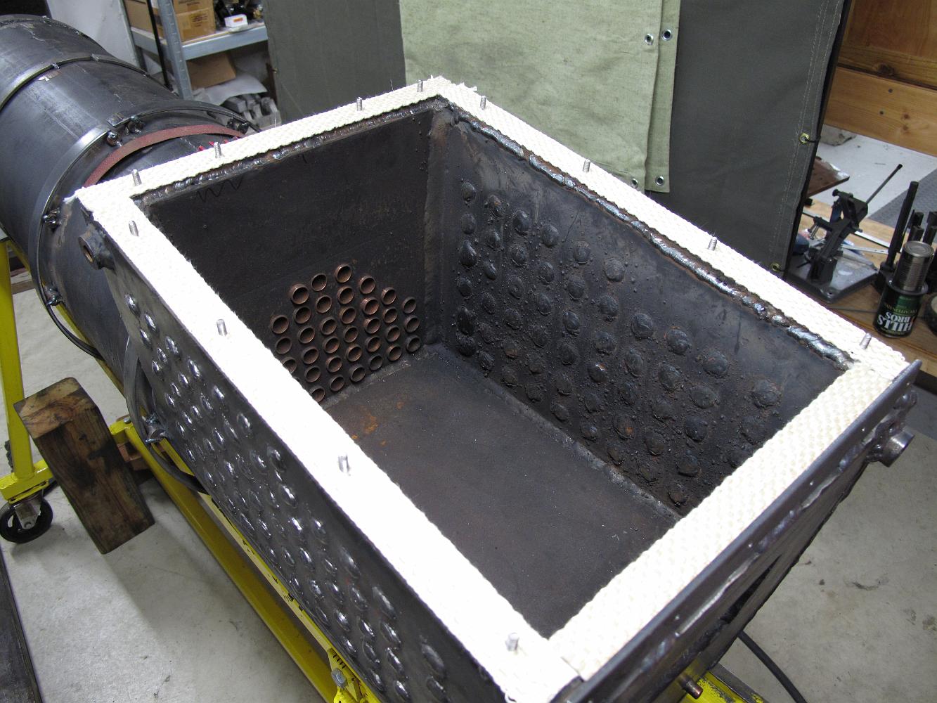
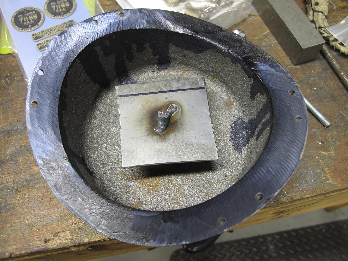
27-Oct-10 I've welded a mounting ring onto the bottom of the boiler with drilled an tapped holes for the 10-32 stainless steel studs which will hold the firepan…
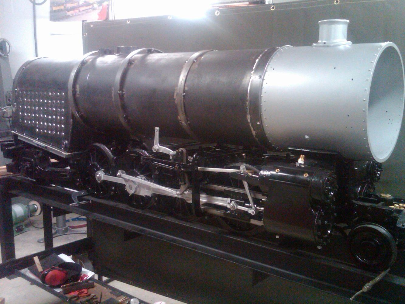
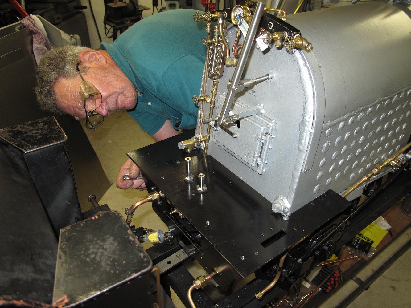
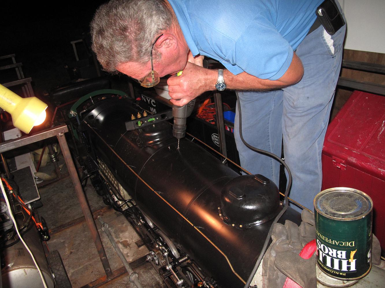
17-Aug-2011 Smokebox mounted to the boiler, on last hook to pull the boiler, install the firepan, check over the chassis for missing pins, nuts, etc., drill the…
19-Sept-2011 The smokebox & boiler are bolted to the cylinders for what I hope is the final time! After tightening the model hex bolts down all around we…
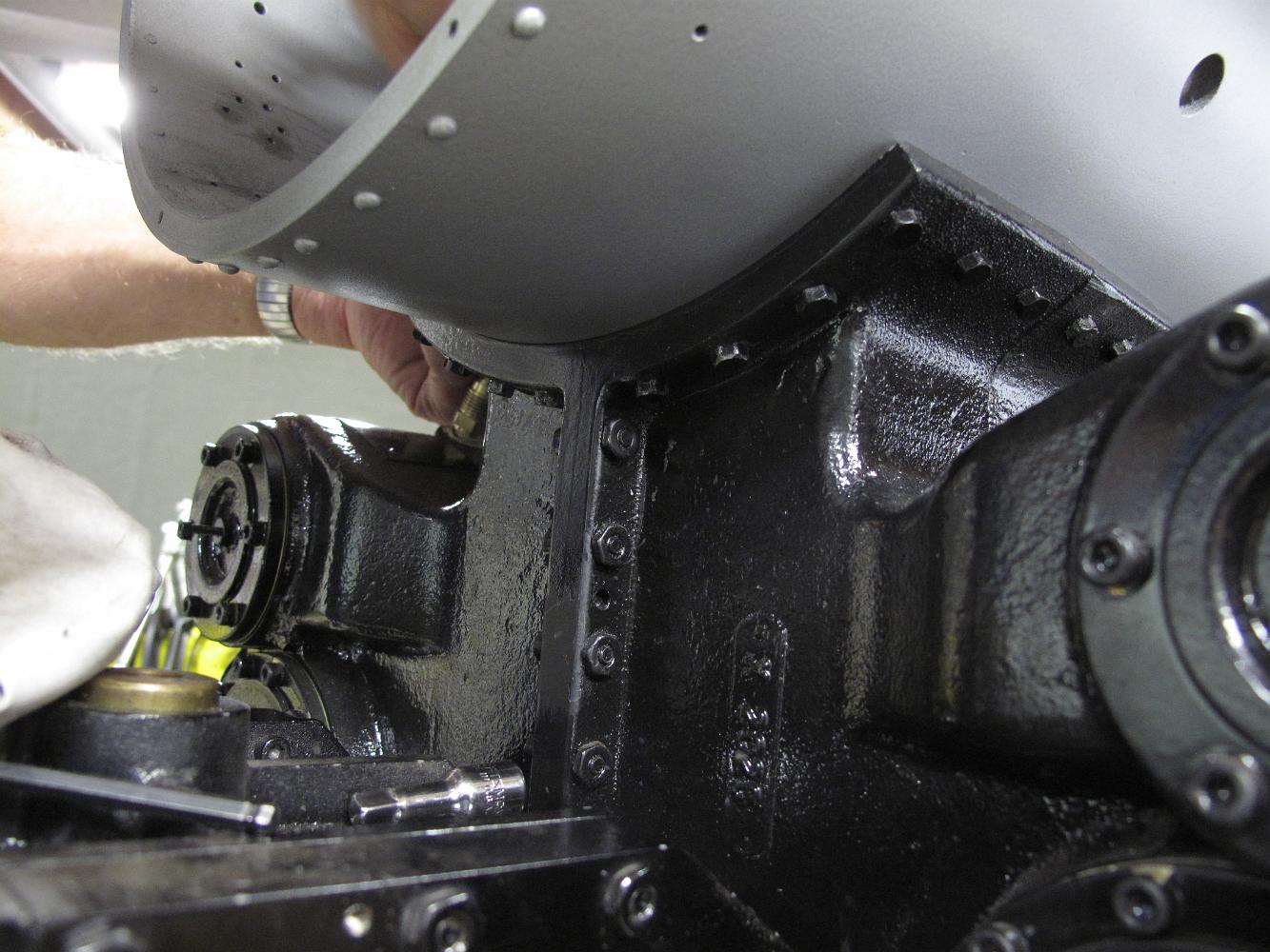
Tightening the smokebox / cylinder mounting nuts. There is copper anti-sieze on the threads, it may help one day (long time from now!) when the shell needs to…
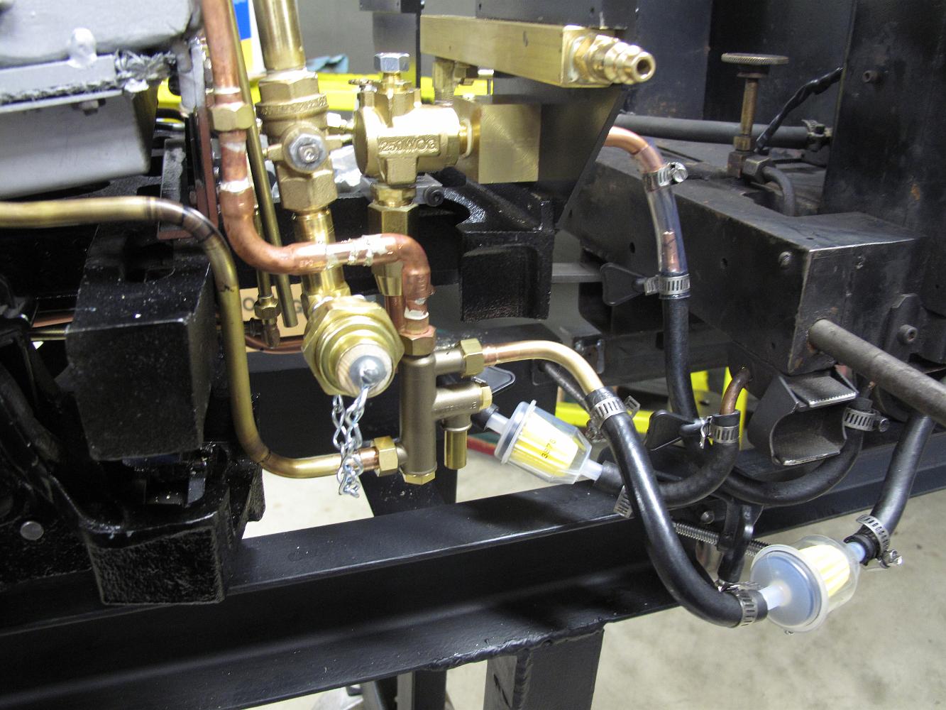
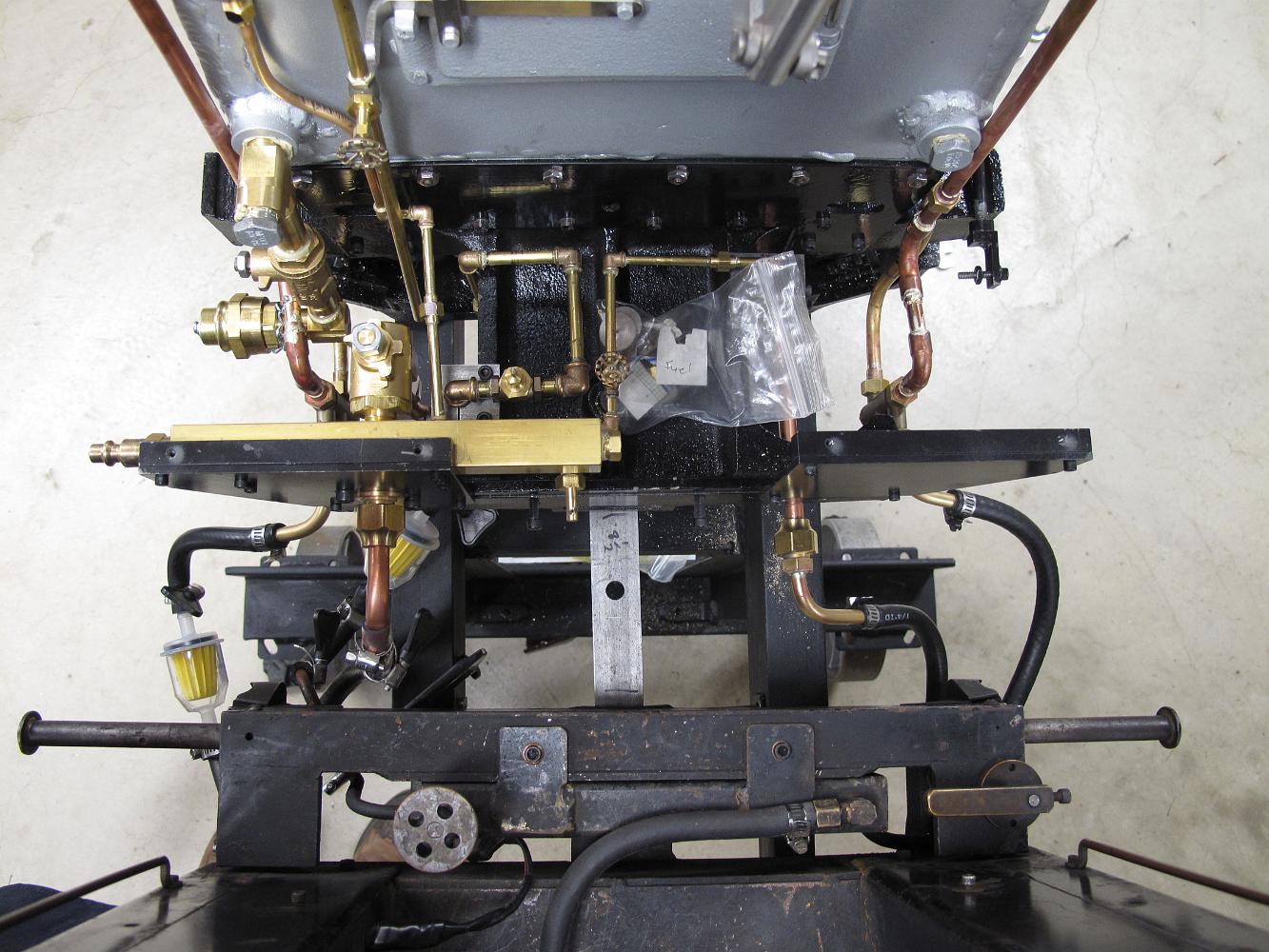
More plumbing work - designing the axle driven water pump bypass valve handle extension with borrowed tender attached to engine.
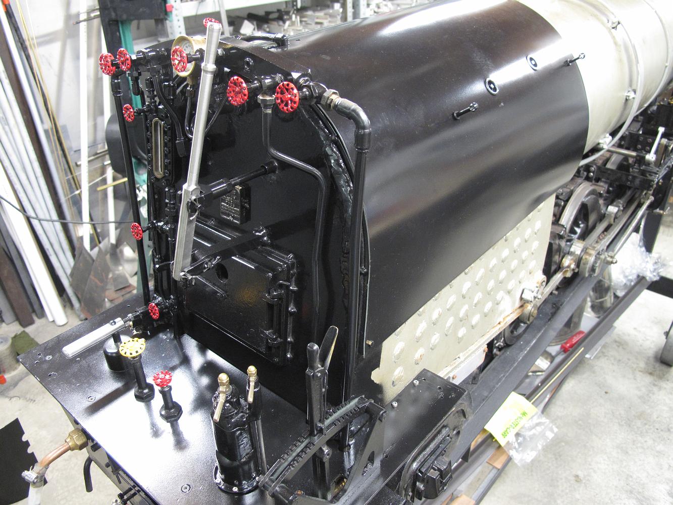
10-Sept-2012 Boiler tag placard welded on backhead. The tag reads: Line 1: MAWP: 125 (Max allowed working pressure) Line 2: TSTWP: 300 (tested pressure) Line 3:…
August 2013 I weld a plate into the sand dome to help hold the lead I am going to pour into it. The blueing on the rim is from fitting it to the jacketing.
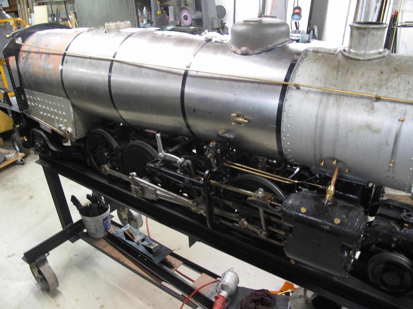
August 2013 The jacketing is trimmed to fit, the sand dome fitted, boiler bands tightened. We test handrail placement. The 0.101 thick jacketing sheet metal is…
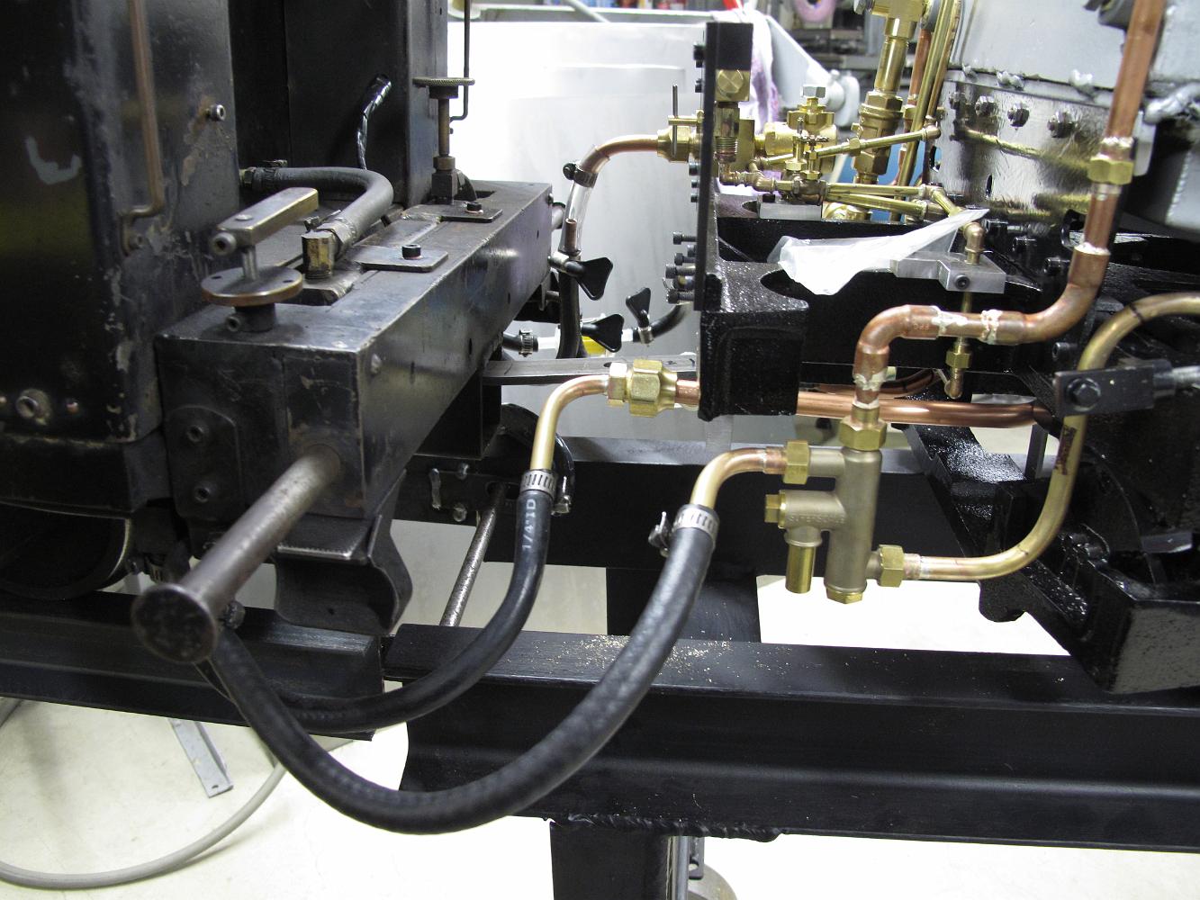
19-Apr-2014 After modifying the front and rear tender bumpers to make the drawbar and coupler heights correct, another trial fitting and plumbing check is…
19-Apr-2014 After modifying the front and rear tender bumpers to make the drawbar and coupler heights correct, another trial fitting and plumbing check is…
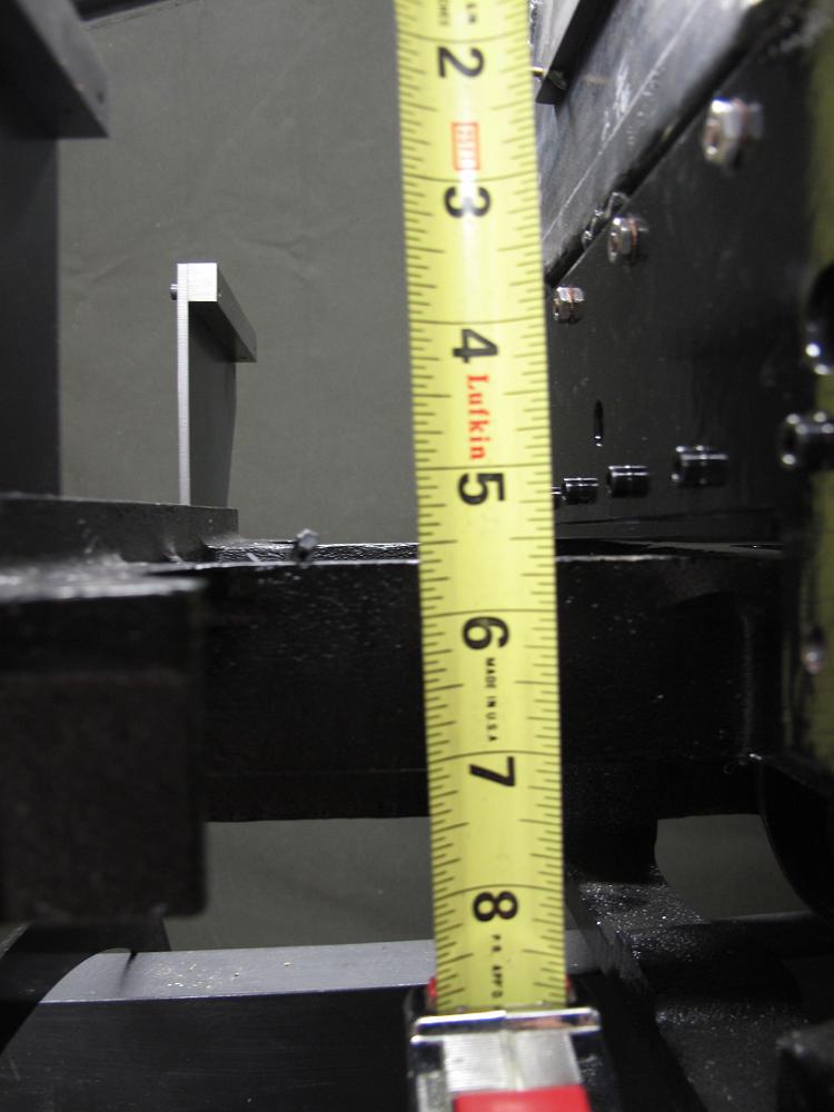
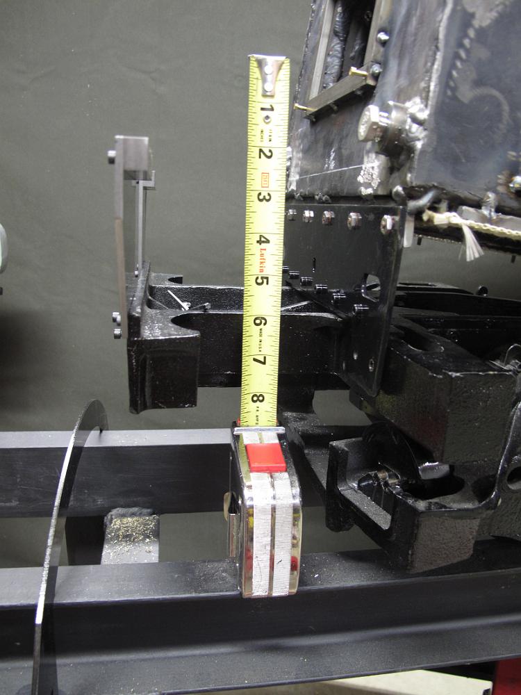
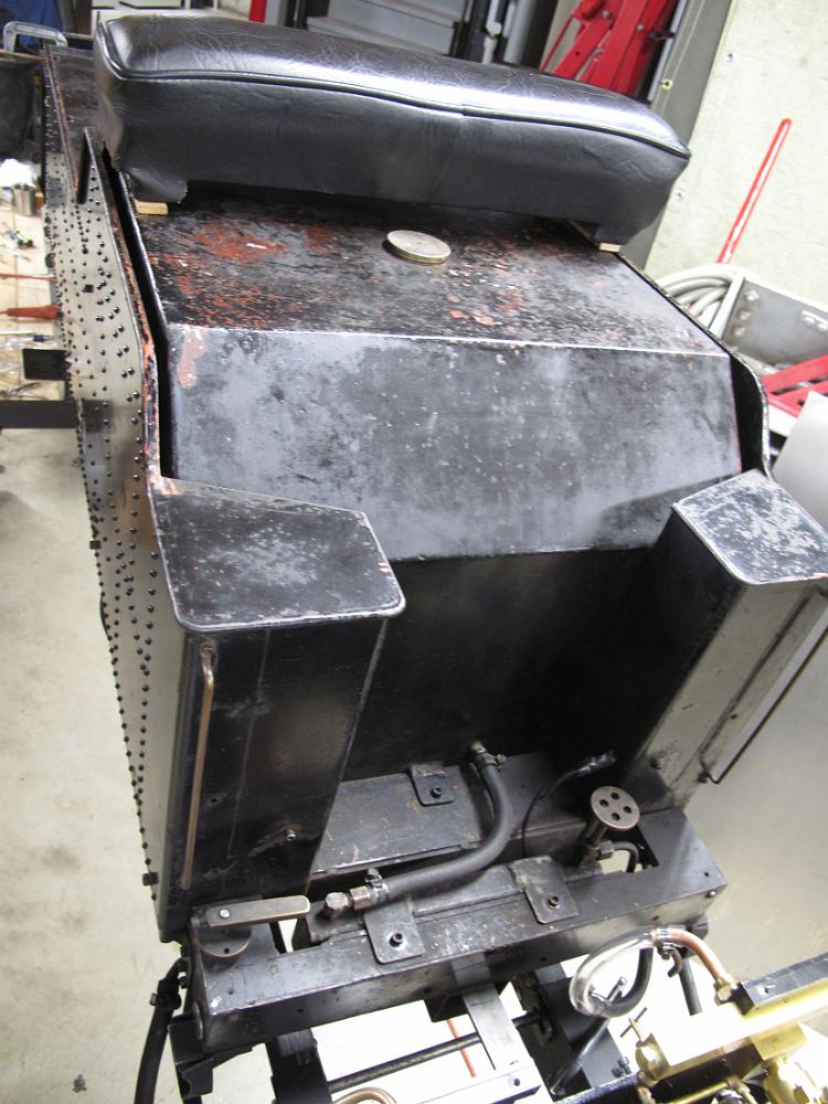
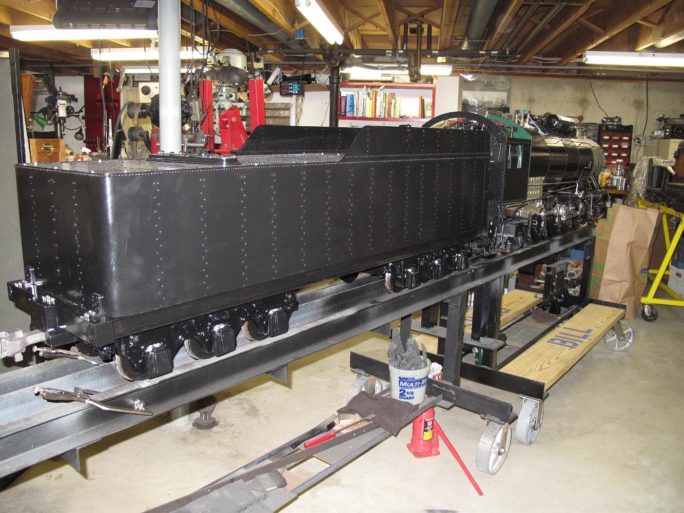
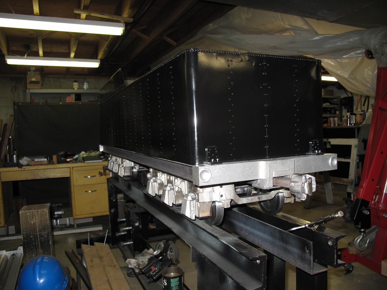
15-Feb-2014 Trial fitting of tender tank on the frame on the assembled trucks, rear view. We discover the frame is 1.5" too tall over the rail with these…
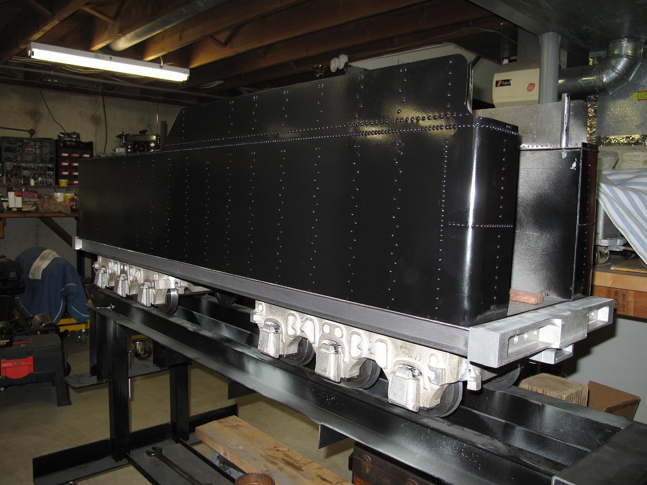
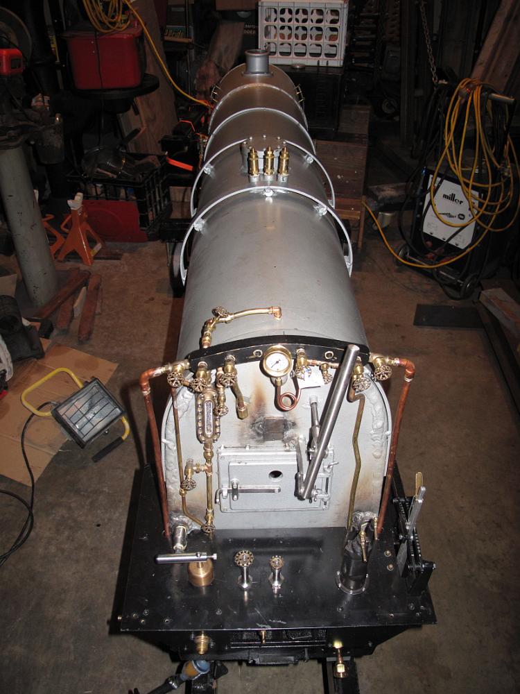
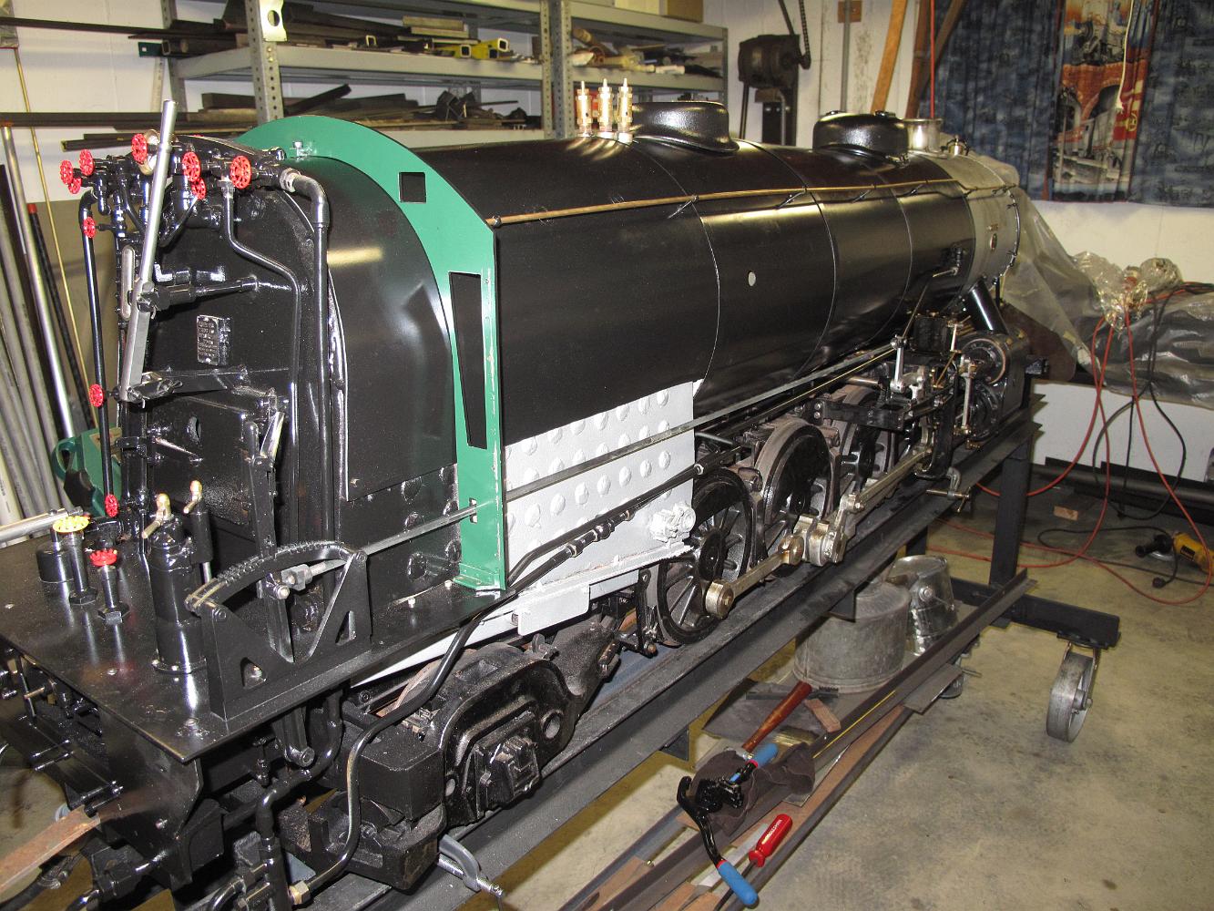
30-Sept-2013 We need to install the air tanks on the top of the engine to complete the Frisco look, but ran out of shop time before we had to bring it out of…
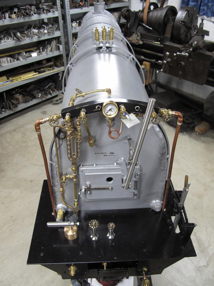
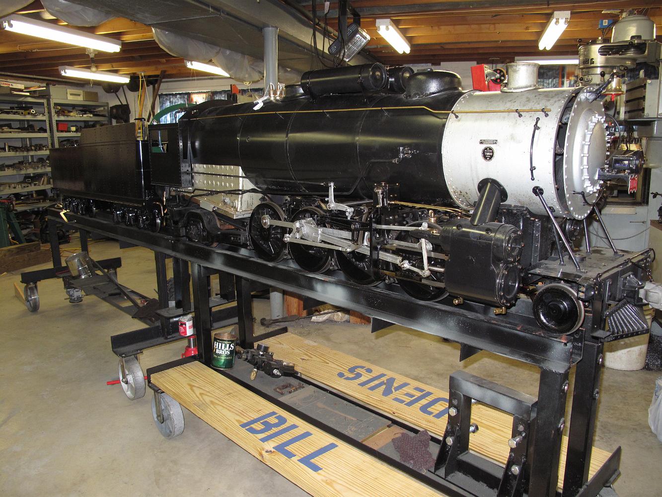
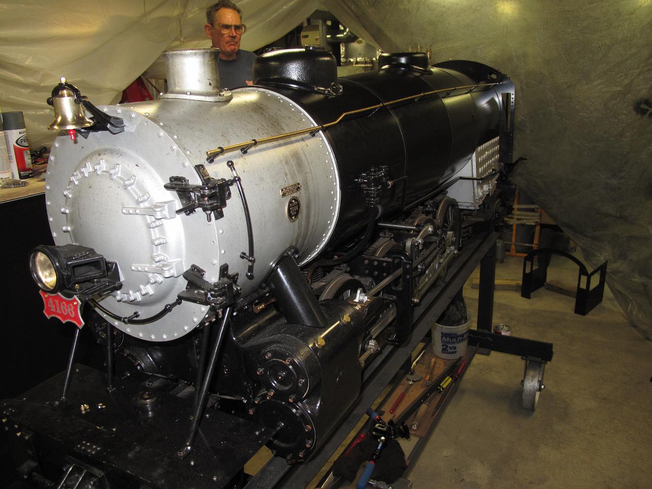
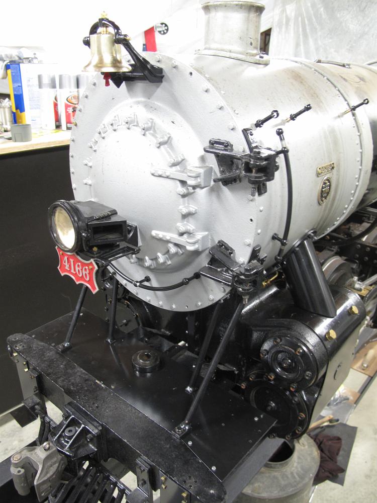
16-Sept-2013 Front view of the engine sporting the bell, handrails, builders plates, jacketing and domes. At last she is starting to look like a complete Frisco…
16-Sept-2013 The jacketing is installed! We thread the handrail down the length of the engine from the cab to the front, and put the two bends in it like the…
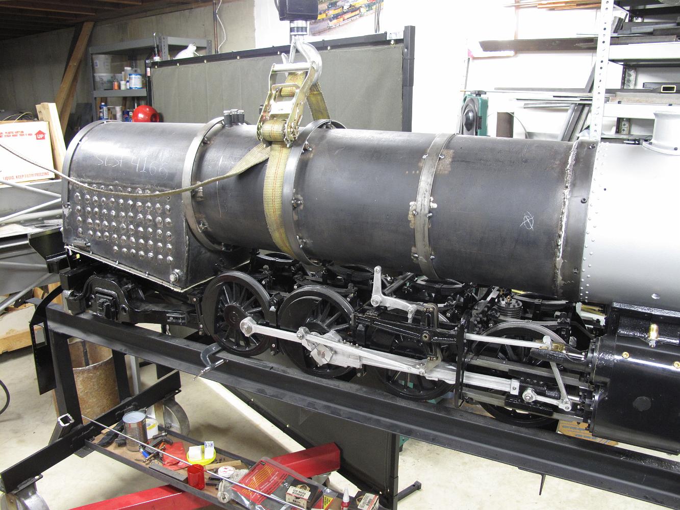
16-Sept-2013 In the process of using a nylon ratchet strap to snug down the jacketing on the boiler (my boiler bands are too short to do this when the jacketing…