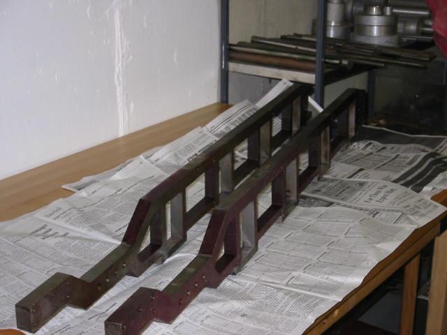
The locomotive frames as purchased.
October 27, 2004 After checking the blueprint specifications, Bill and I discovered the frames had been machined too thick. They were supposed to be .812, but…
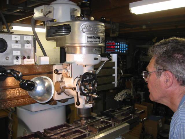
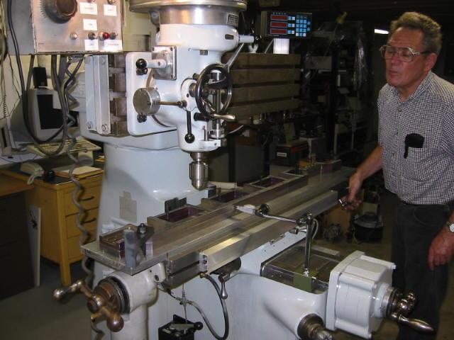
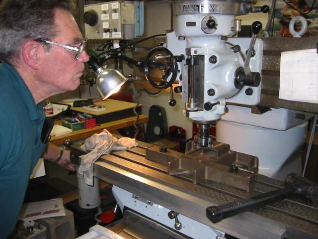
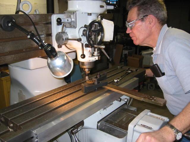
27-Oct-04 Here we see Bill at the controls bringing the frame thicknesses a lot closer the blueprint specifications. This was the first serious amount of work…

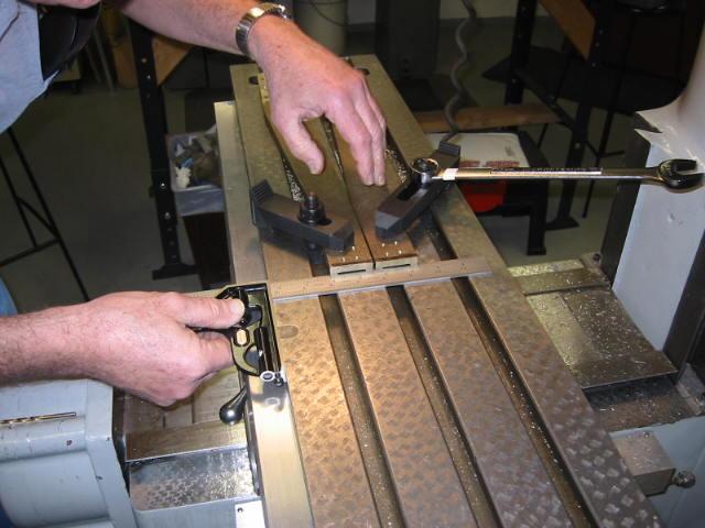
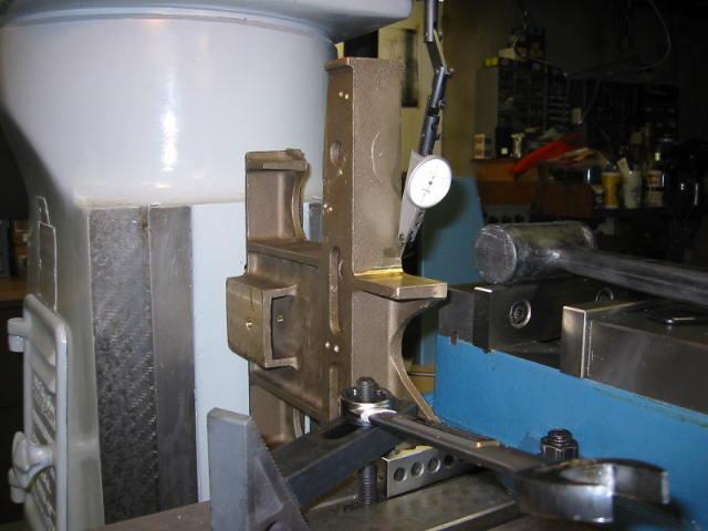
17-Nov-04 Now that the frames are at the proper thickness, we check out the rest of the dimensions. Here Bill is indicating the top of the frame to make it…
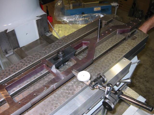
17-Nov-04 A close-up of how the frame was 'indicated', which is to say we used a Dial Test Indicator which shows how far + or - 0.0005 (one-half of…
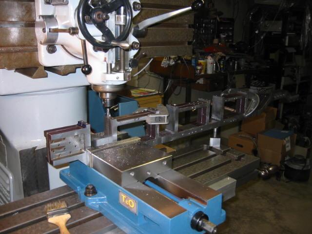
24-Nov-04 The sacrificial tool plate table has been bolted to the top of the table. Both frames are stacked on each other and have been pinned together to…
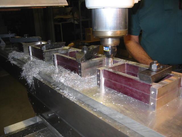
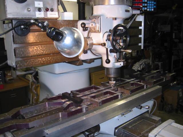
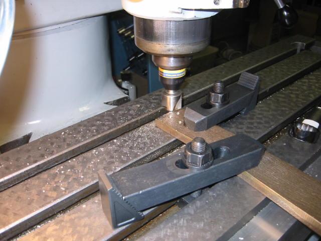
Dec-1 Machining the Axle box openings on the frames. You're looking at both frames, dowel pinned together and bolted to the table from the back of the…
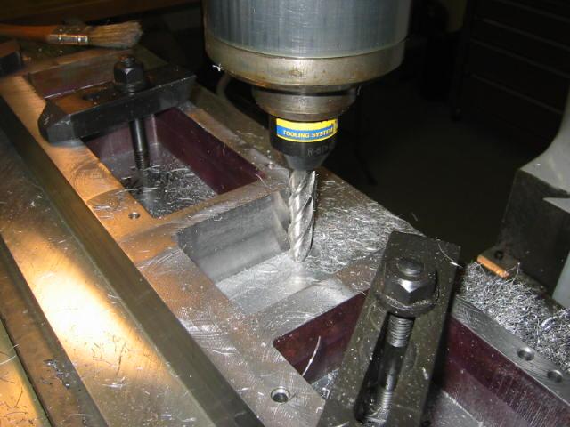
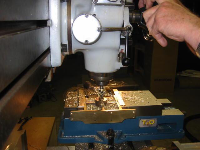
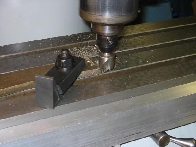
Dec-1-04 Action shot of milling the axle box openings. This 2" long 1/2" milling cutter is just barely cutting into the sacrificial table below while we use…
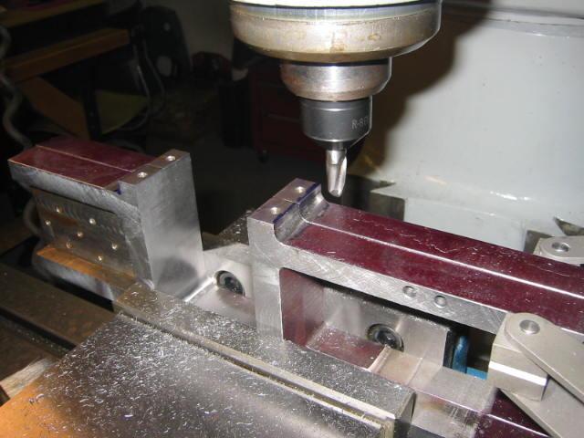
8-Dec-04 Machining the pedestal binder ears to a uniform size. They all will end up small than what is shown on the print, and will different end for end, but…
8-Dec-04 Hanging the frames off the vice to complete the pedestal machining. Once I finish this opening, and drill the tail frame holes, the frames will be…
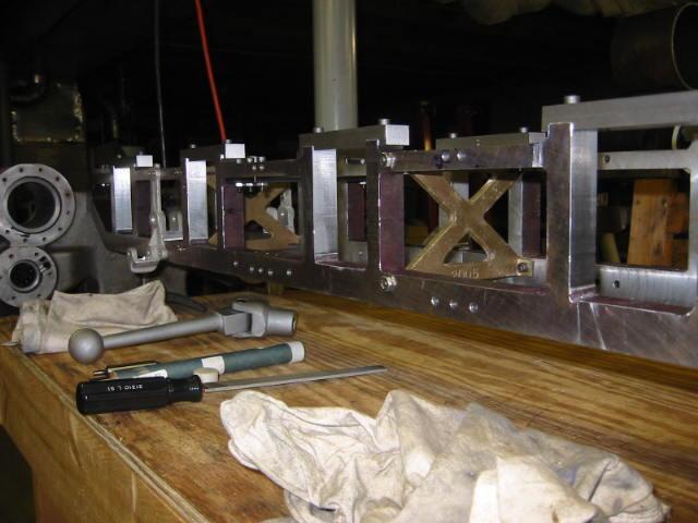
12-Jan-05 A small milestone: All the machining on the frames is complete! The pedestal binders have been made and bolted across the jaw openings, the frames…
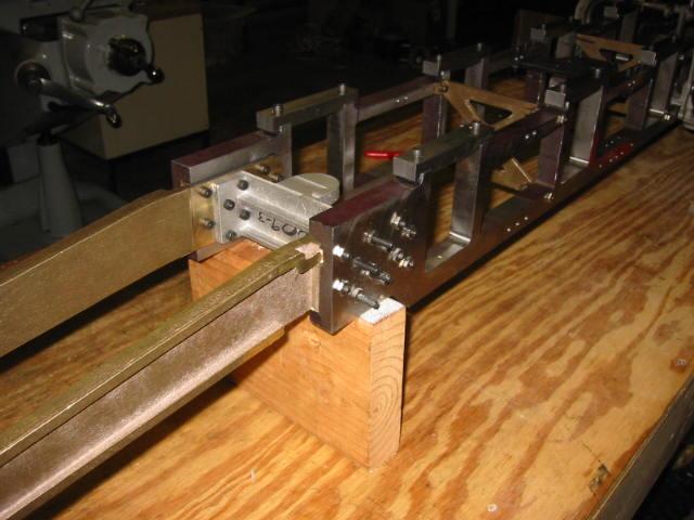
3-Feb-05 More work on the frame group. The aluminum rear frame spreader was finished and match drilled in place. Also the brass frame extensions have been…
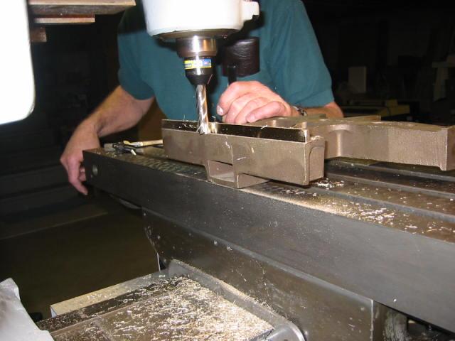
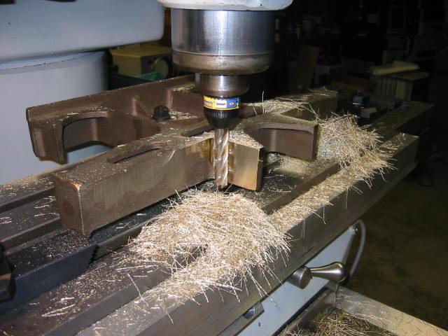
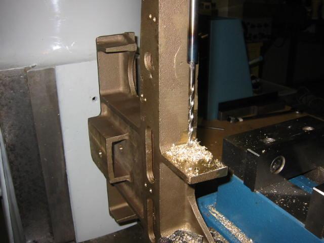
24-Feb-05 Drilling a hole in the brass front frame spreader. The stringy brass produces long chips.
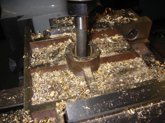
24-Feb-05 Boring the pilot truck pivot hole in the front frame spreader. The hole needed to be 1.000 and I didn't have a boring bar big enough. Bill tried…
3-Mar-05 Putting a flat spot on the large brass tail cradle casting. The blueprint does not call for many machined surfaces, and we didn't have a way to hold…
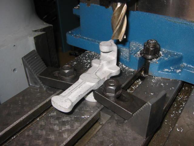
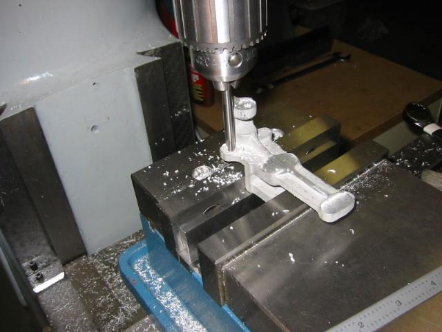
3-Mar-05 Cleaning up the cab mounting bracket. With the machined surface bolted down to the table, we were able to come up a square surface.
3-Mar-05 Machining the tail cradle frame mounting points. Once again, the mighty 'T-Ram' Bridgeport proves its worth. After we machined the back of the tail…
10-Mar-05 Squaring the frame extensions in preparation for machining a radiused edge to match the tail frame cradle.
10-Mar-05 Putting a radiused edge on the end.
10-Mar-05 Bill puts a radiused edge on the other frame extension. Due to the way the casting was warped, we couldn't lay it on the table and securely clamp it…
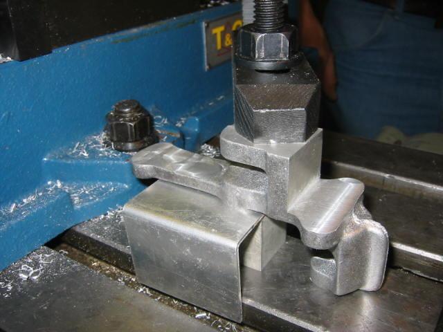
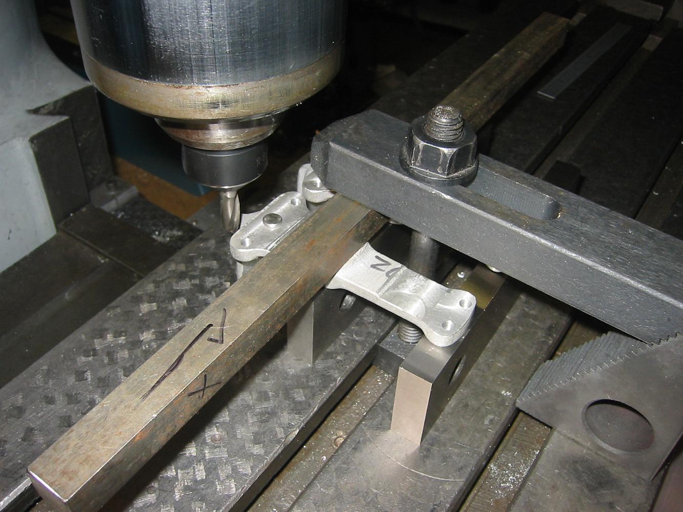
A challenging setup, machining the tailpiece cradle. We are trying to make the 'ears' on this piece parallel and the correct width for the side rails to bolt…
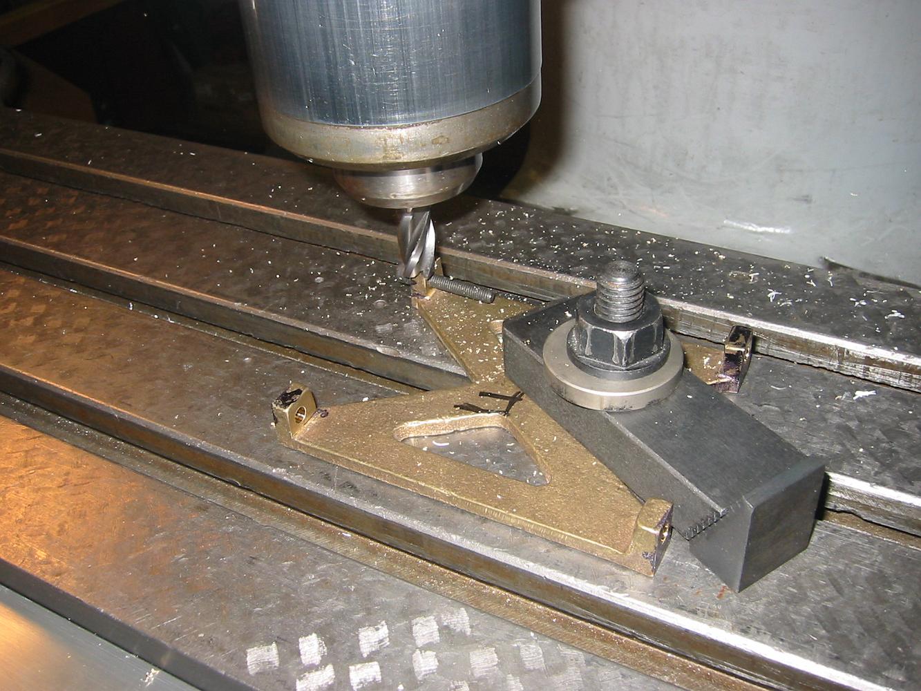
17-Mar-05 Using a homemade drill extension soldered to a twist drill, we make our own aircraft drill since the spindle cannot get close to the casting where the…
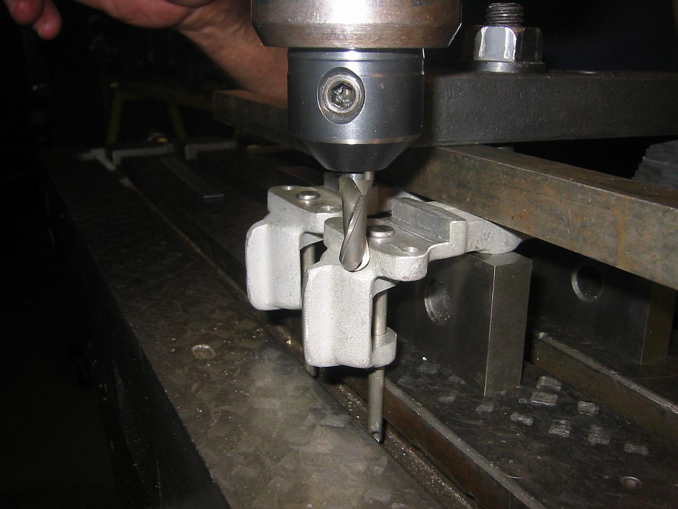
7-Apr-05 These brake hanger castings were hard to hold onto, with little reference surface to measure from. One of the first things to do is skim cut a portion…