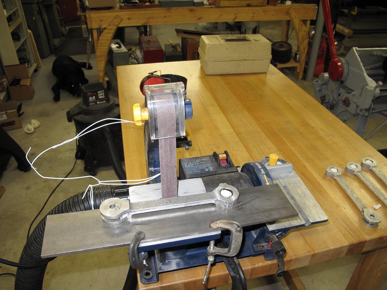
17-July-09 I experiment using the belt sander to clean up the appearance of the rods. Note the fancy coathanger retaining clip holding the shop vacuum hose to…
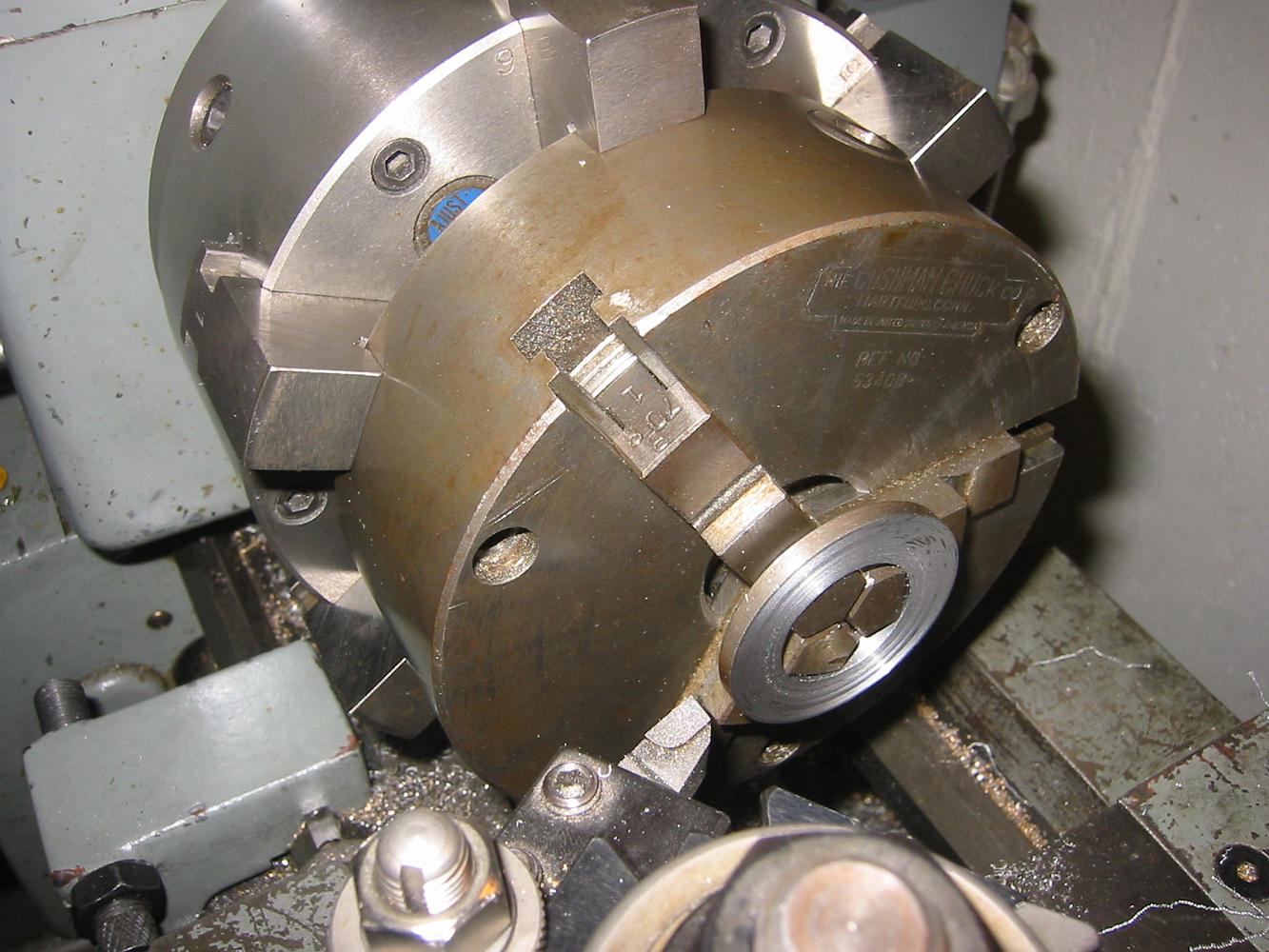
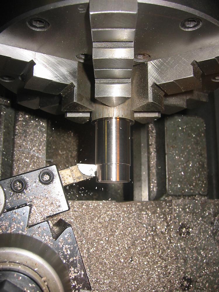
9-July-08 Here's a setup I've never done before: Chucking a chuck to hold the part. Bill did not want to make an expanding mandrel just for two parts, so we…
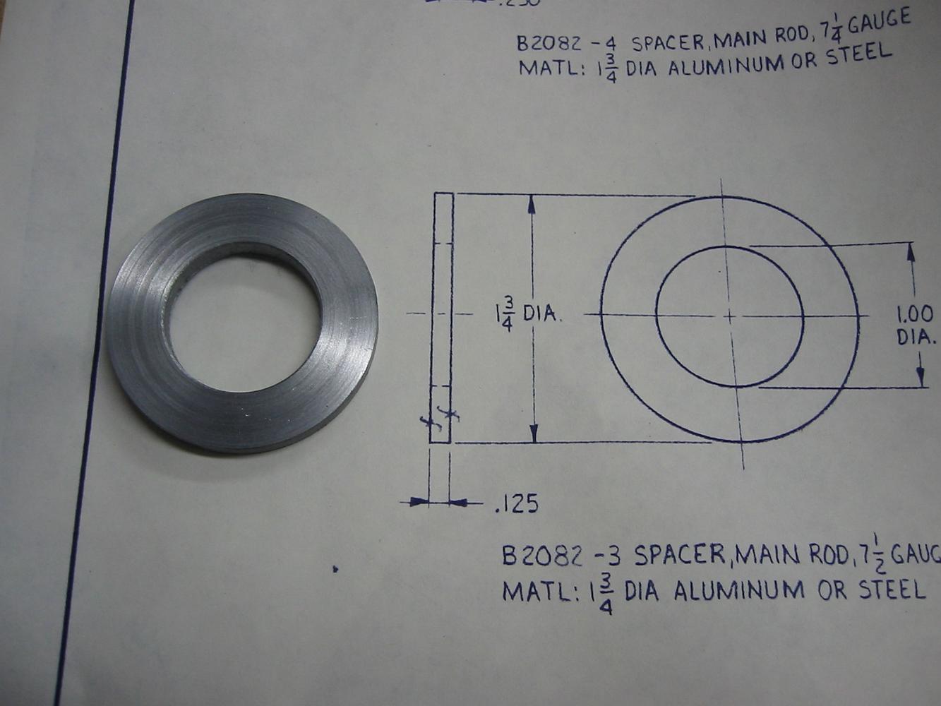
A finished spacer in steel.
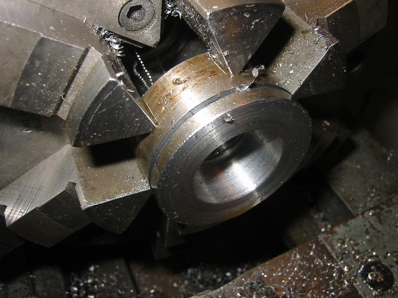
9-July-08 Turning the rod spacers from a piece of mystery steel from the scrapbox.
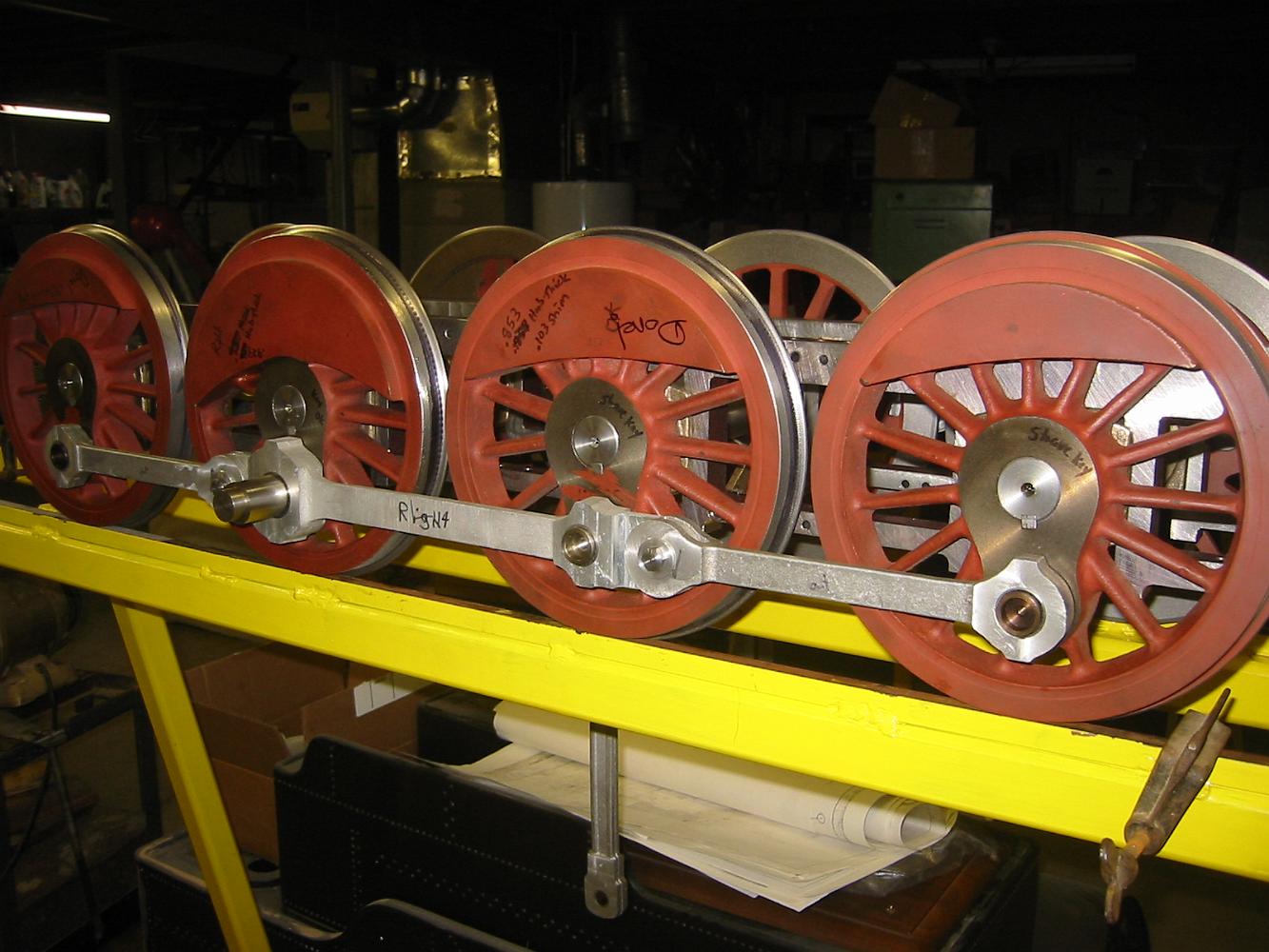
A Milestone!! The rods are fitted to the wheels and the chassis still rolls! Yea! 25-June-08
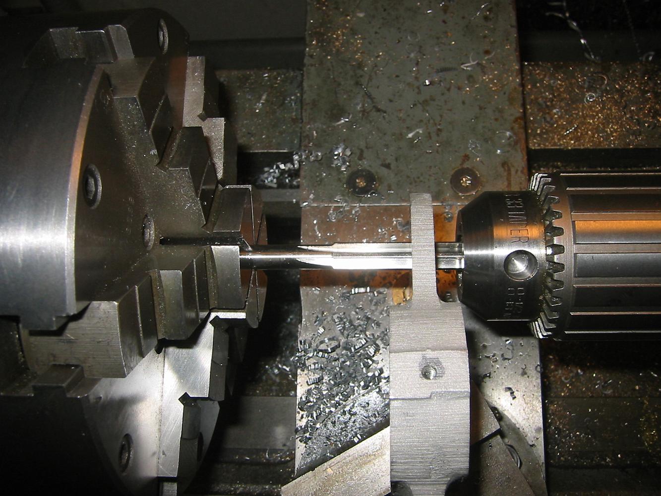
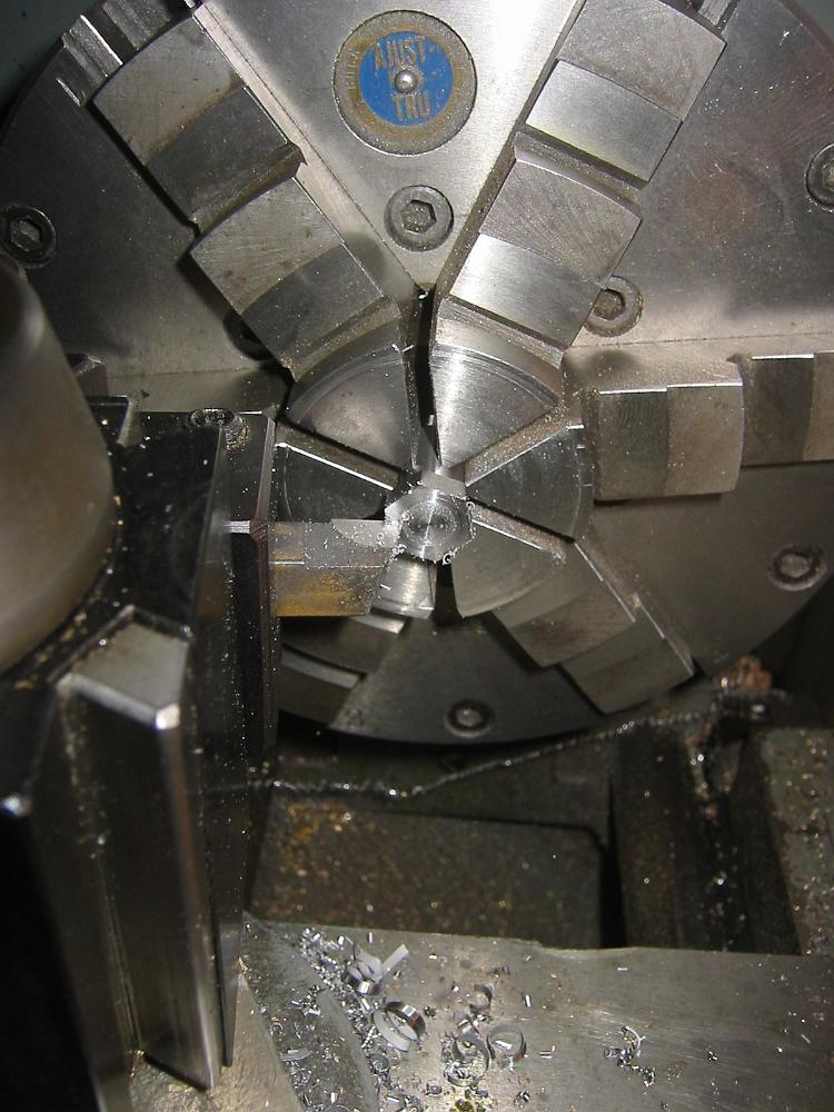
25-June-08 Using a reamer in the lathe (held by the chuck) to open and deburr the bearing brass bushings in the intermediate rods. We used the nose of the drill…
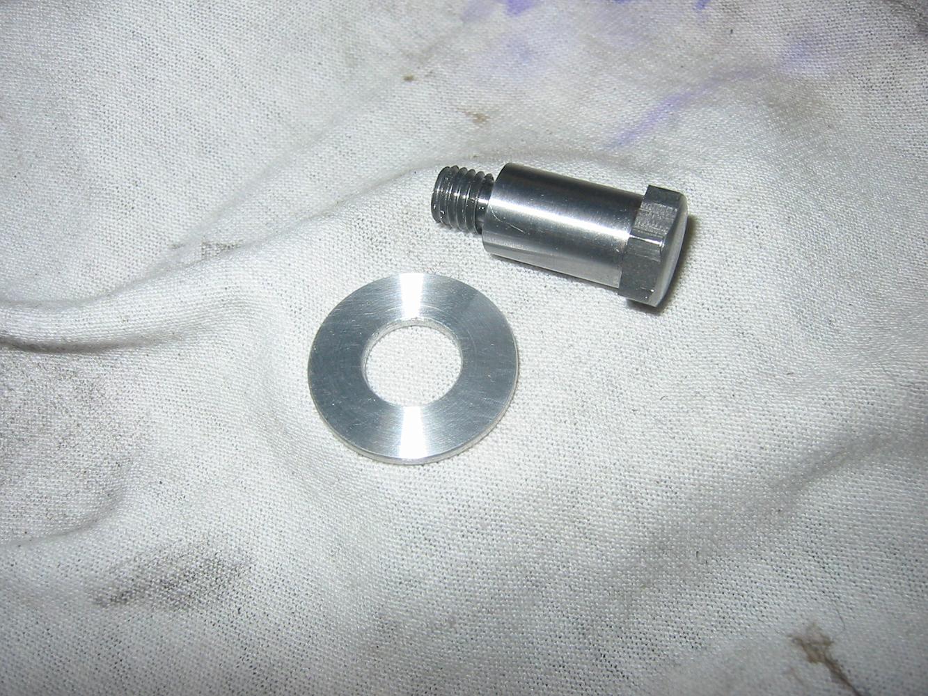
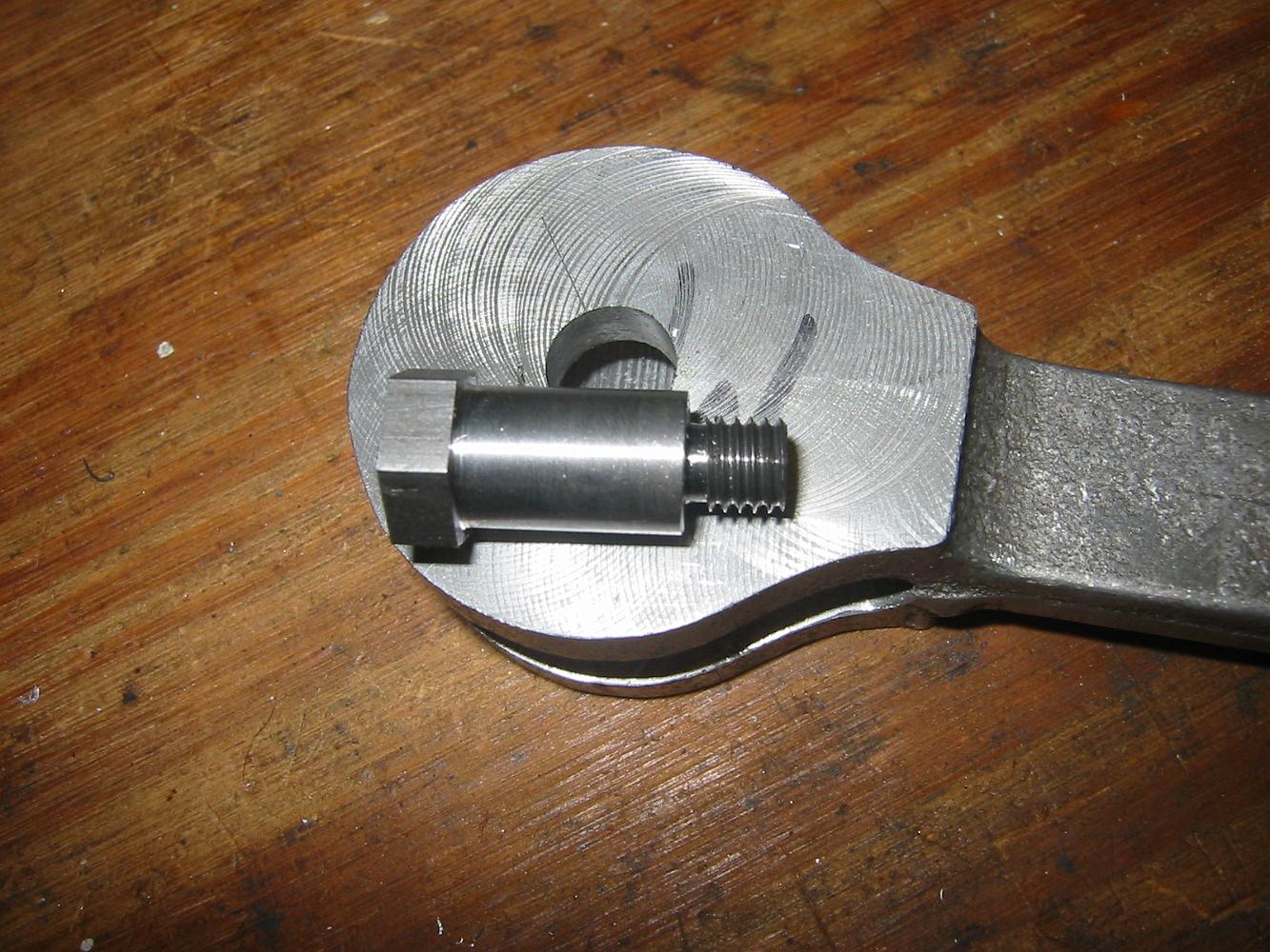
The finished knuckle pin and aluminum washer for the rods. The head of the pin is slightly crowned with a neat finish.
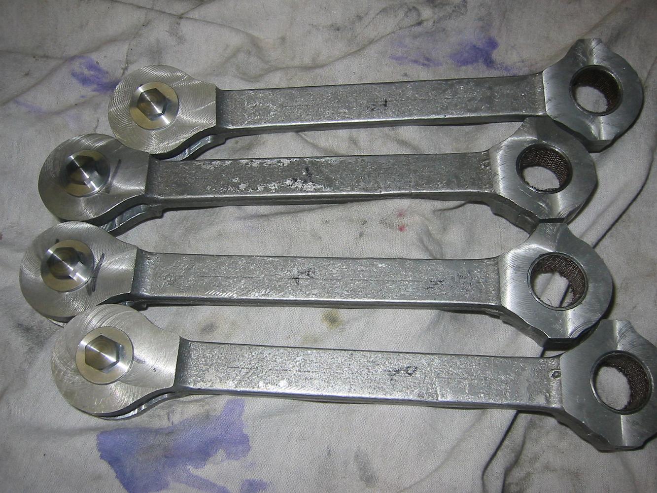
25-June-08 The finished end rods with knuckle pins and washers in place.
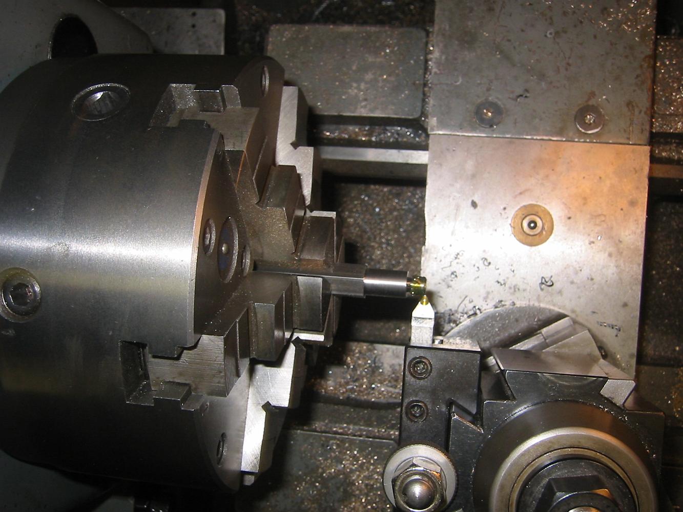
Finishing the knuckle pins. After all the turning operations, the pin is held in the chuck, faced to size. To put a slight crown on the bolt, Bill left the tool…
19-June-08 Threading the knuckle pin. I used lead bearing steel for the pins, I can get a better surface finish out of this steel than plain cold rolled.
19-June-08 The finished knuckle pin with it's rod.
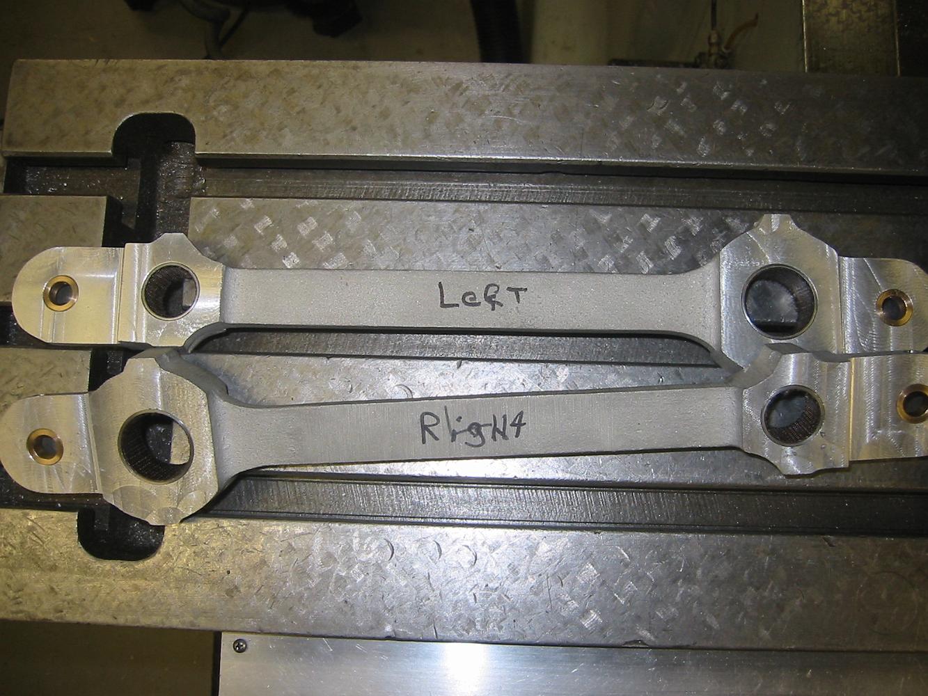
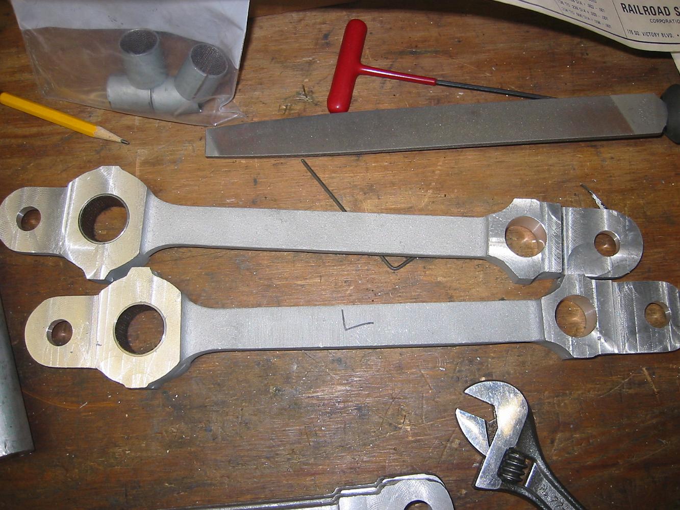
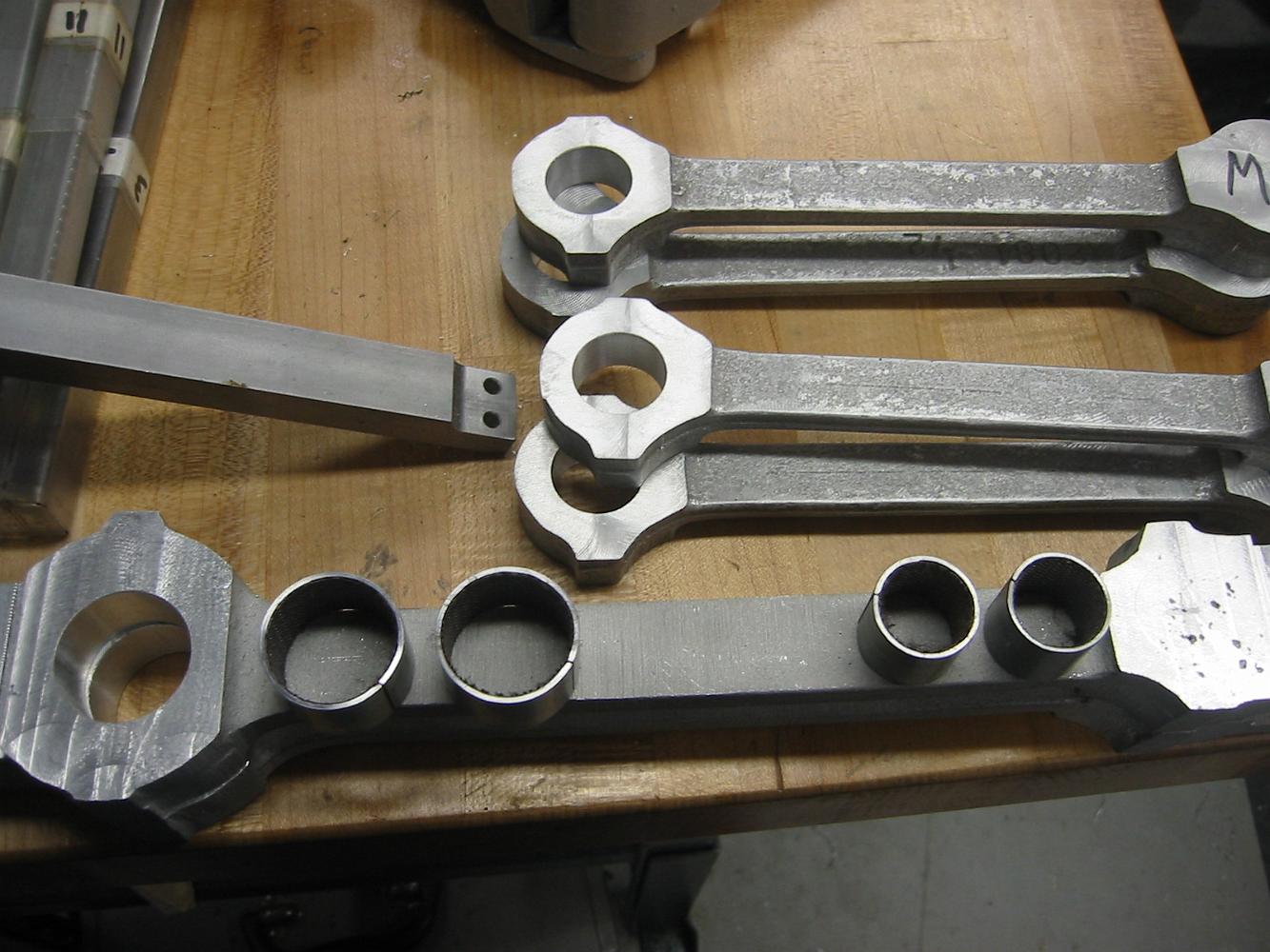
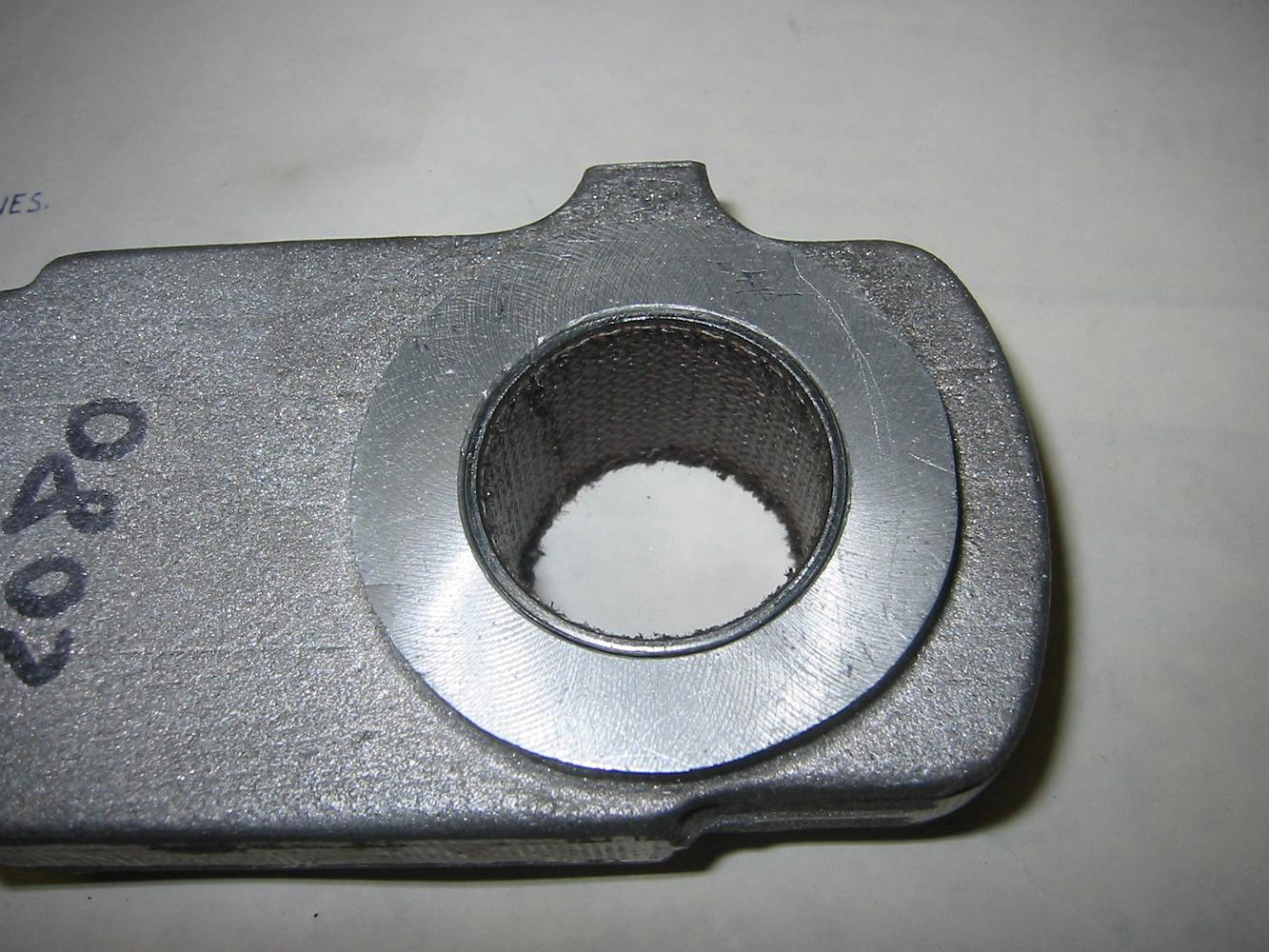
The finished intermediate rods with the bushings in.
Boring the bearings out of bearing brass.
Turning the bearing brass down to size
19-June-08 The end rods bored and cut, ready for bearings.
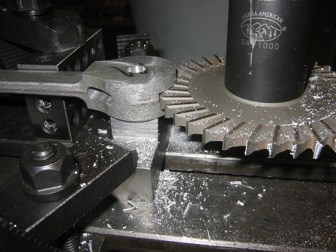
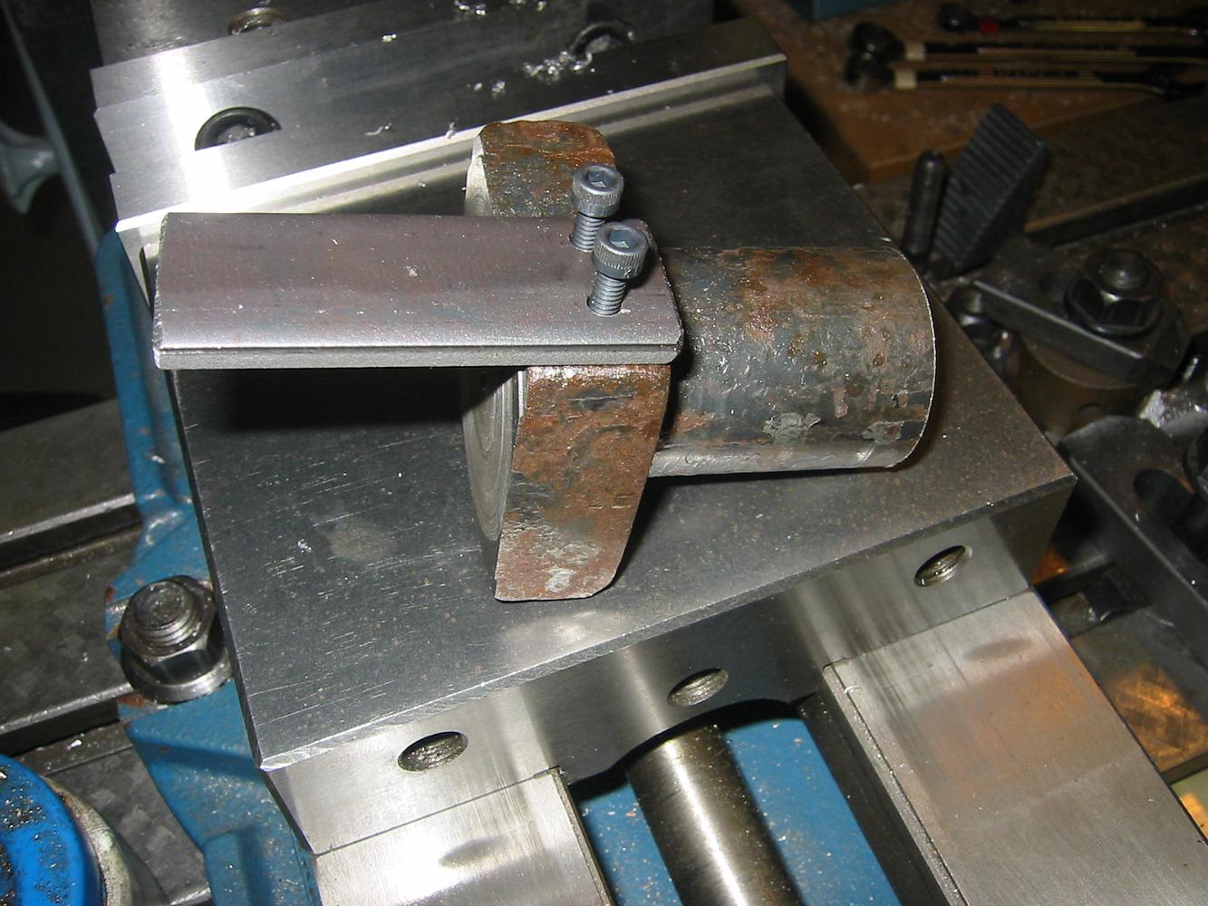
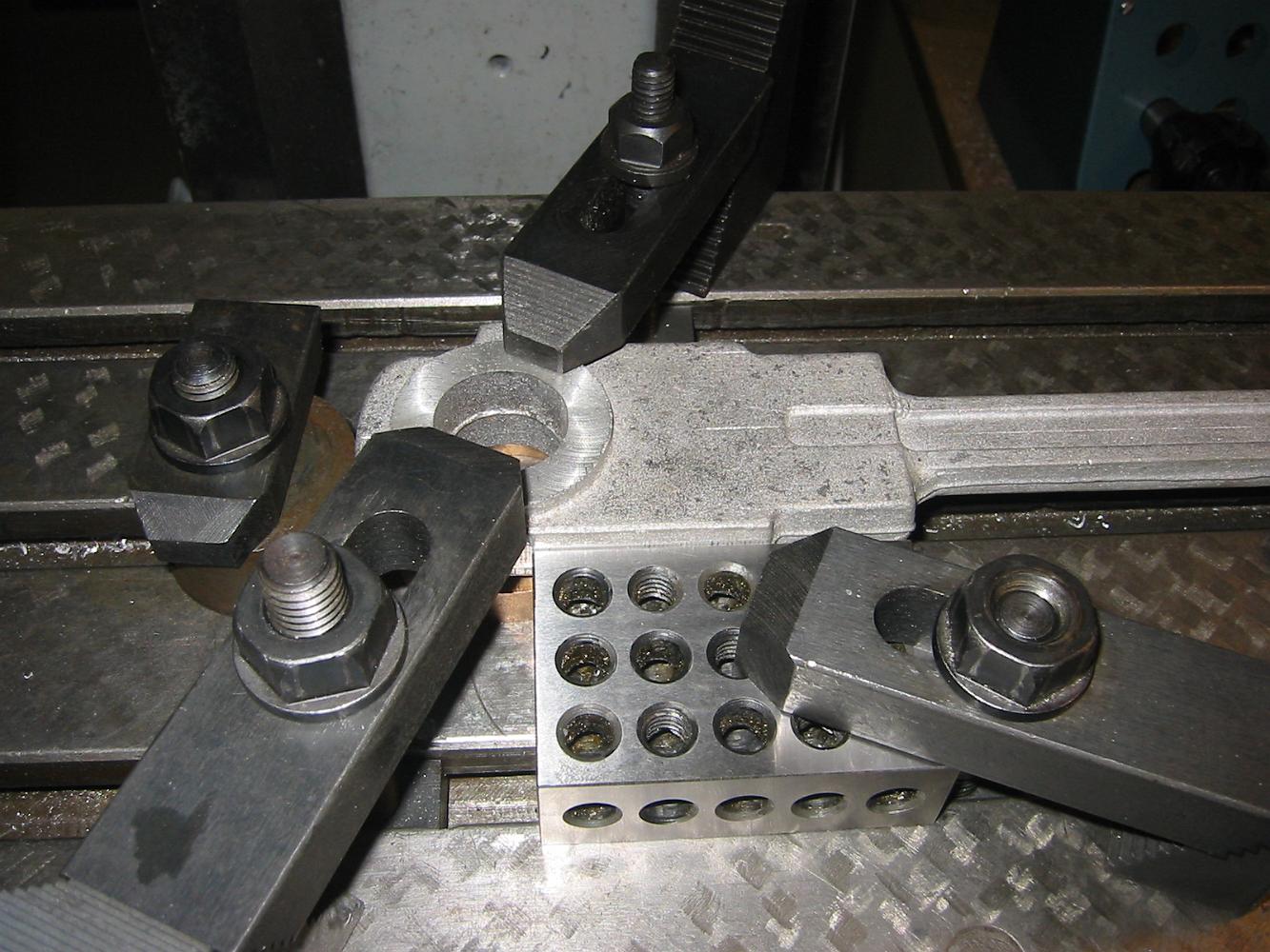
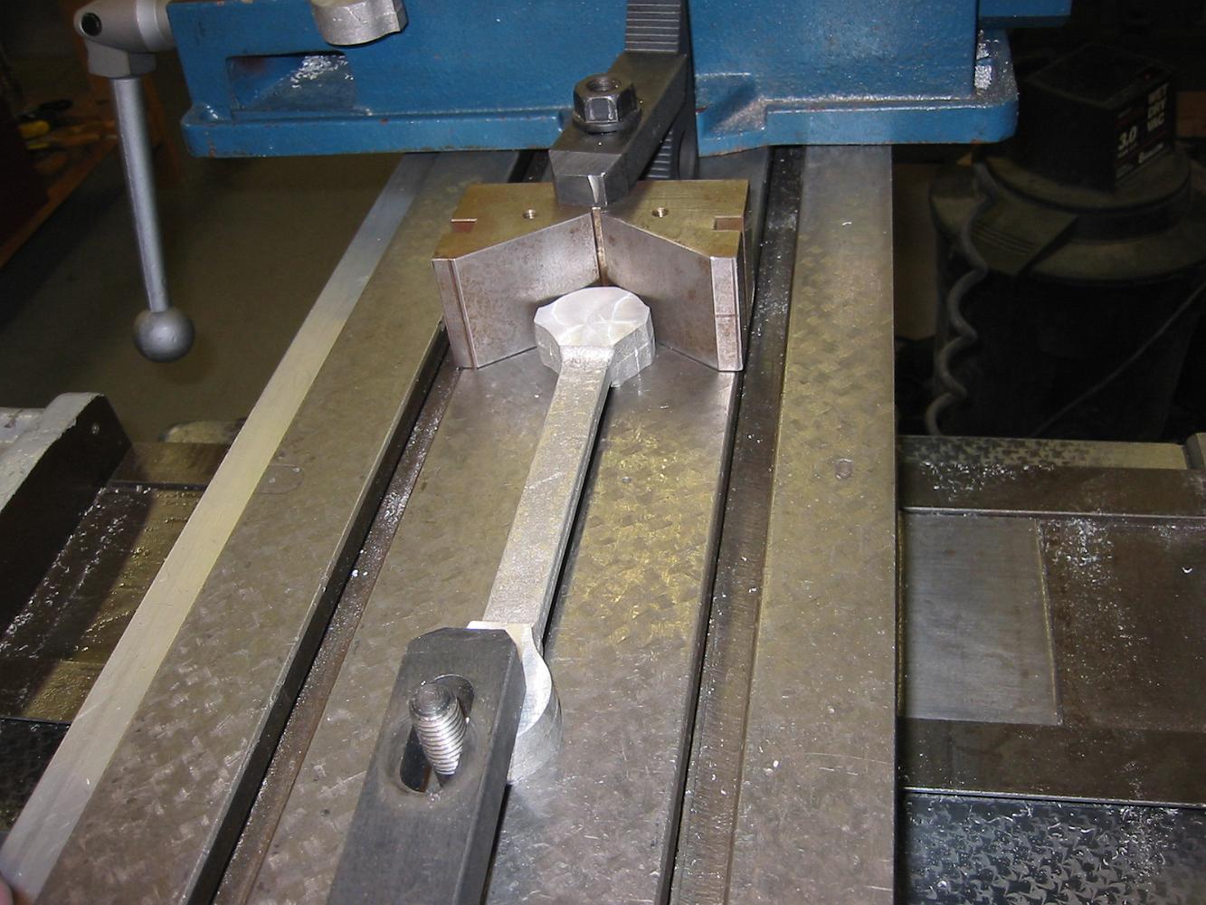
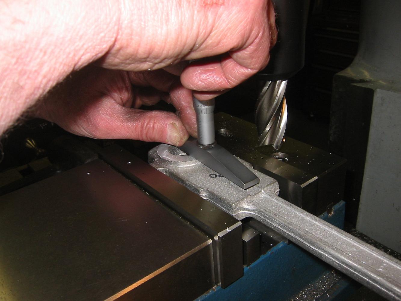
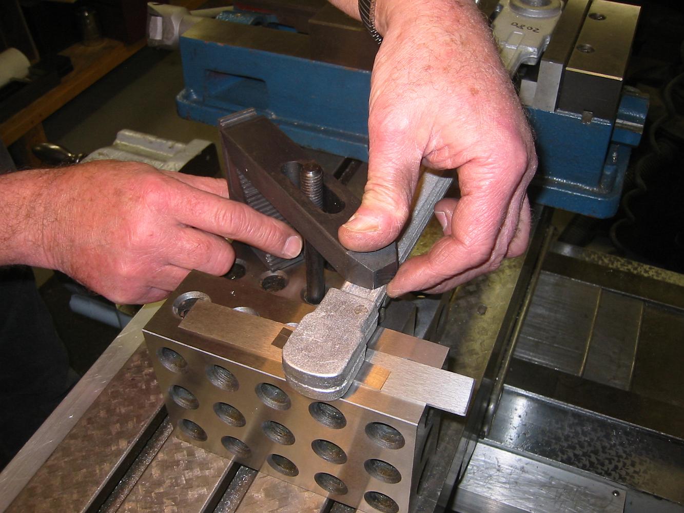
Slotting the end rods. The rod is bolted from the bottom to the t-shaped fixture under the clamps, a 1-2-3 block is placed against the side of the rod to…
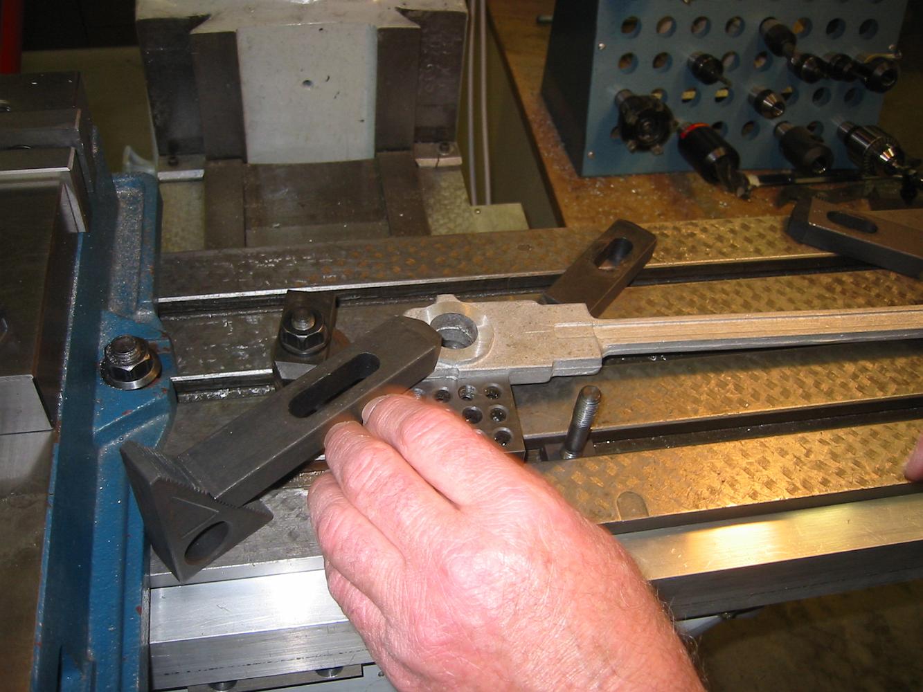
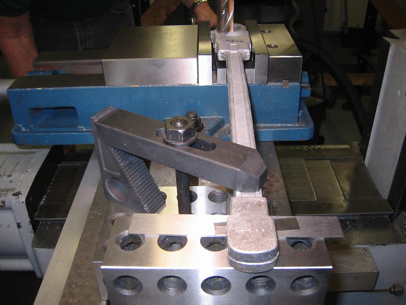
Setting up to use the side cutting saw to cut the slot.
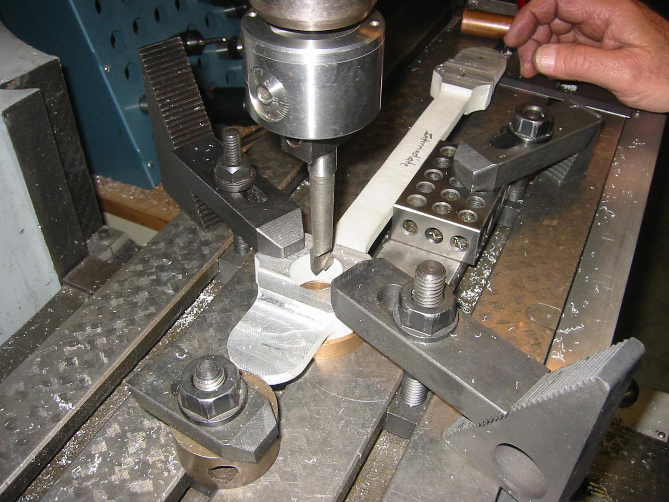
11-June-08 Boring the rod end.
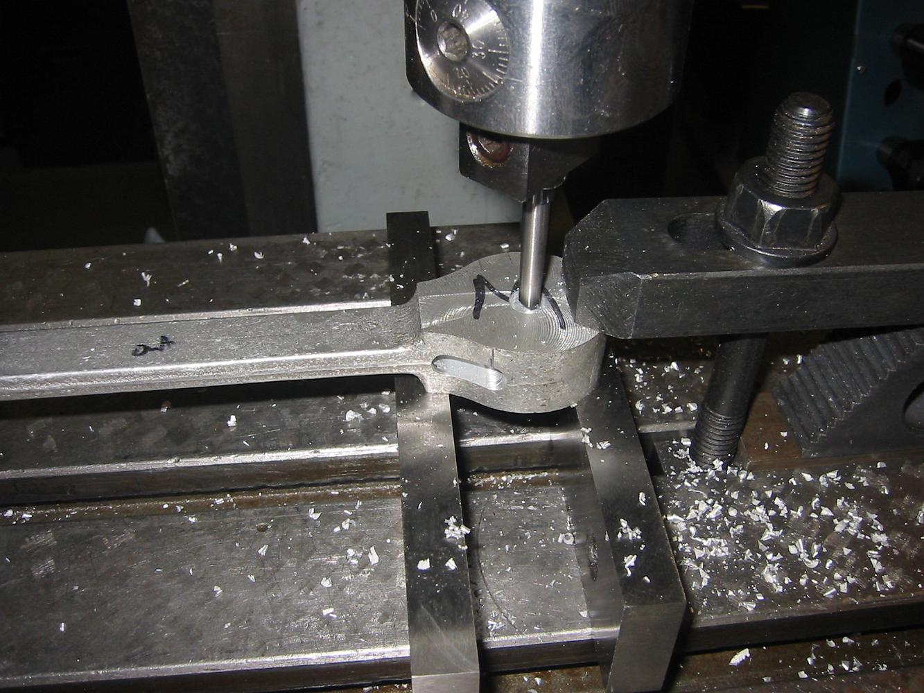
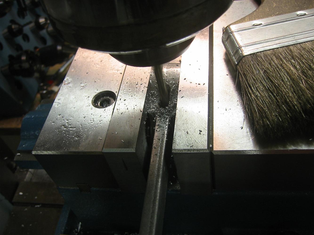
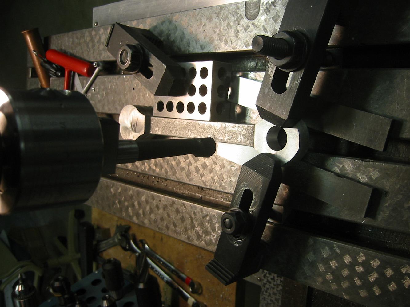
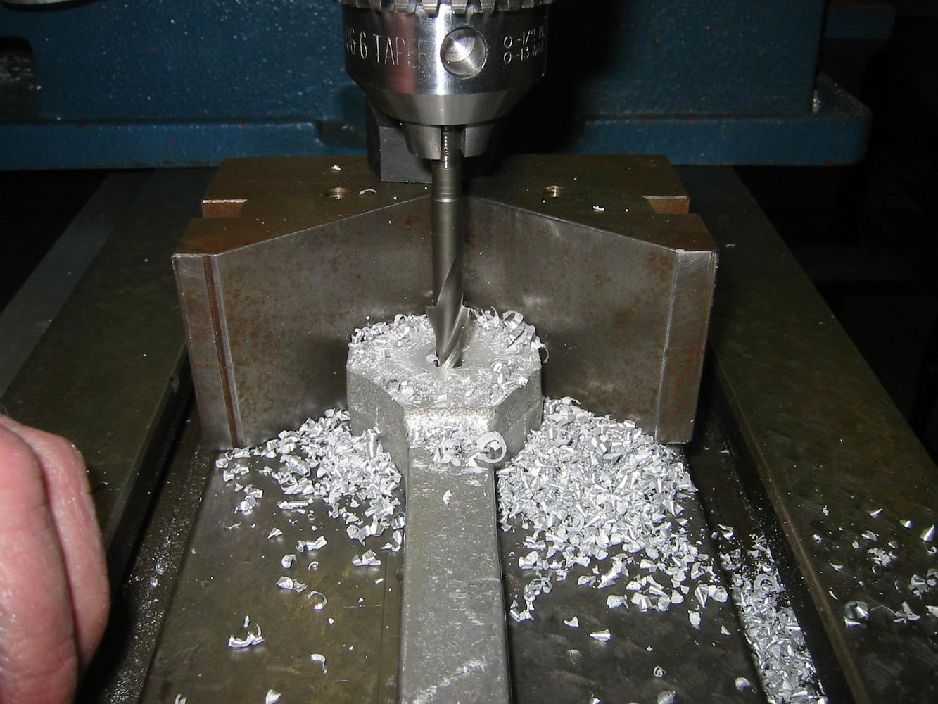
11-June-08 With the end rod securely held at the crankpin end, under the stack of washers on the tool holder, the other end is drilled so we can tap and bore…
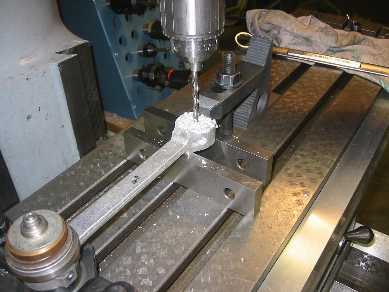
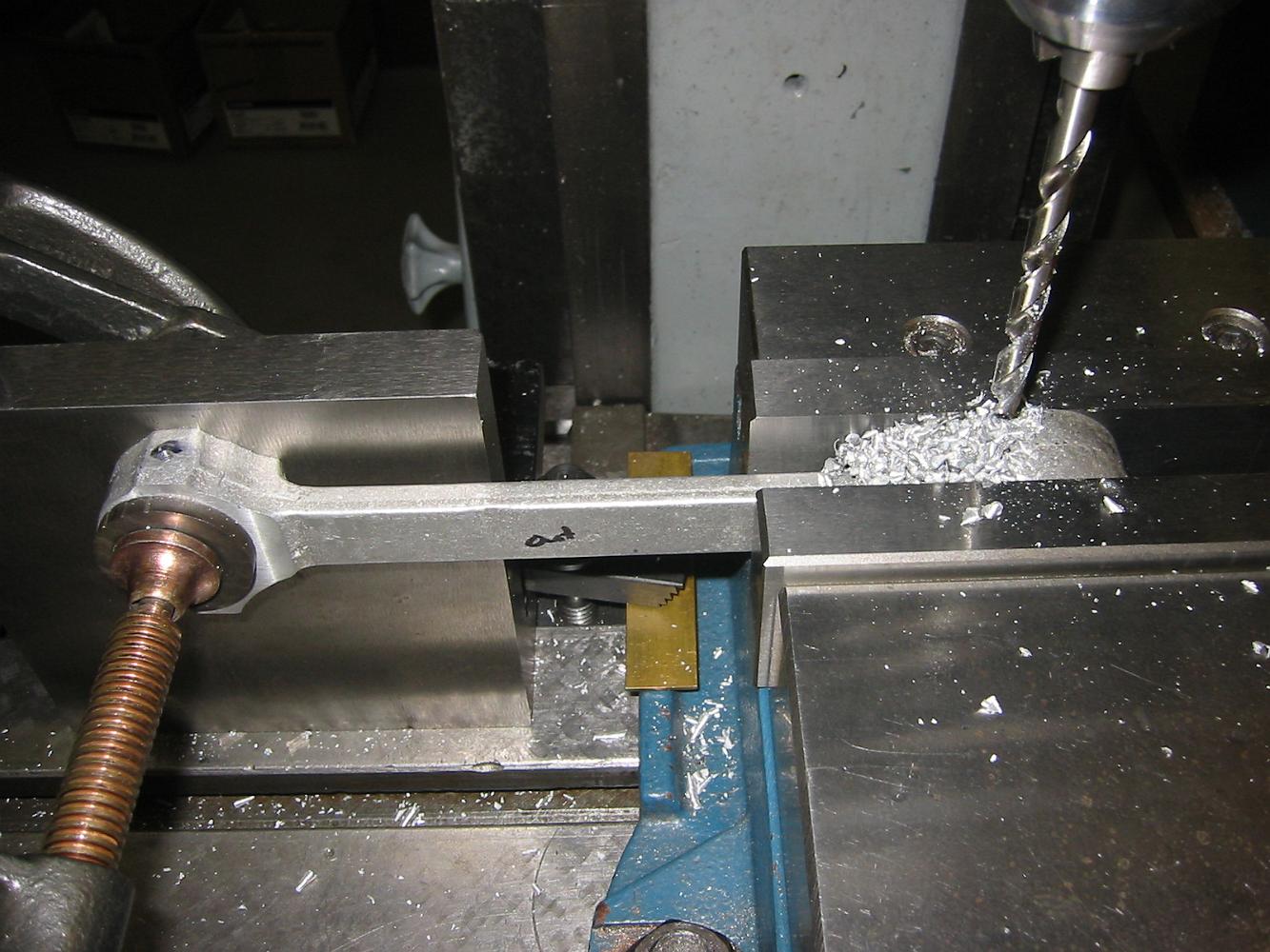
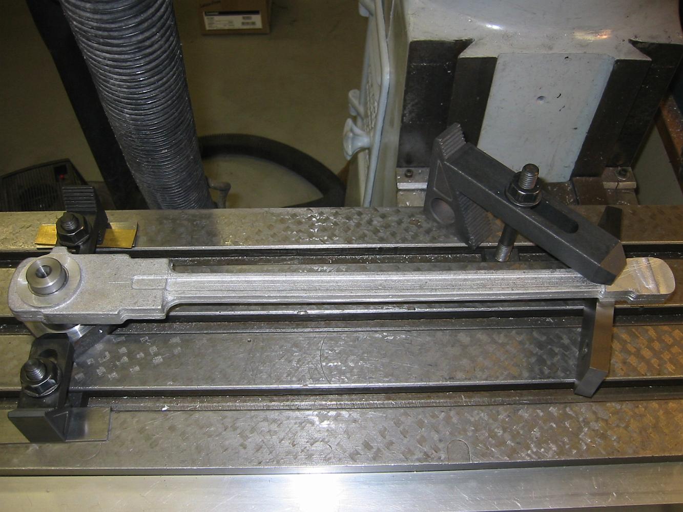
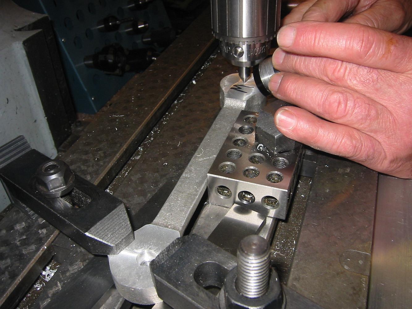
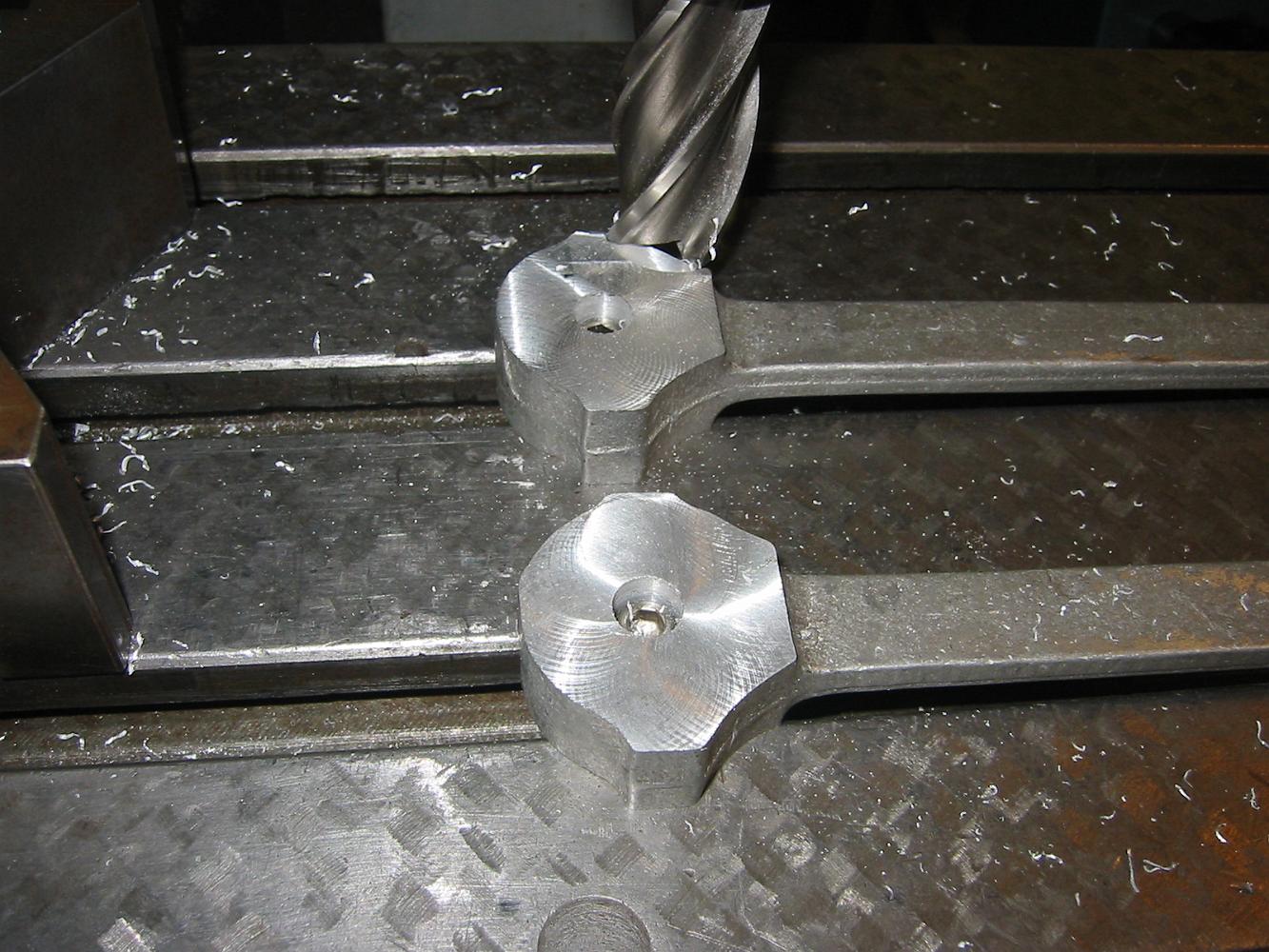
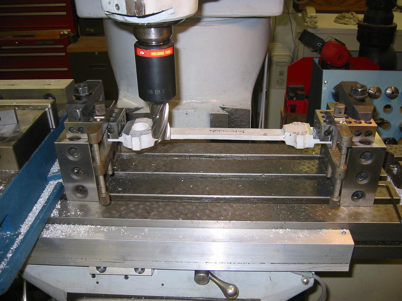
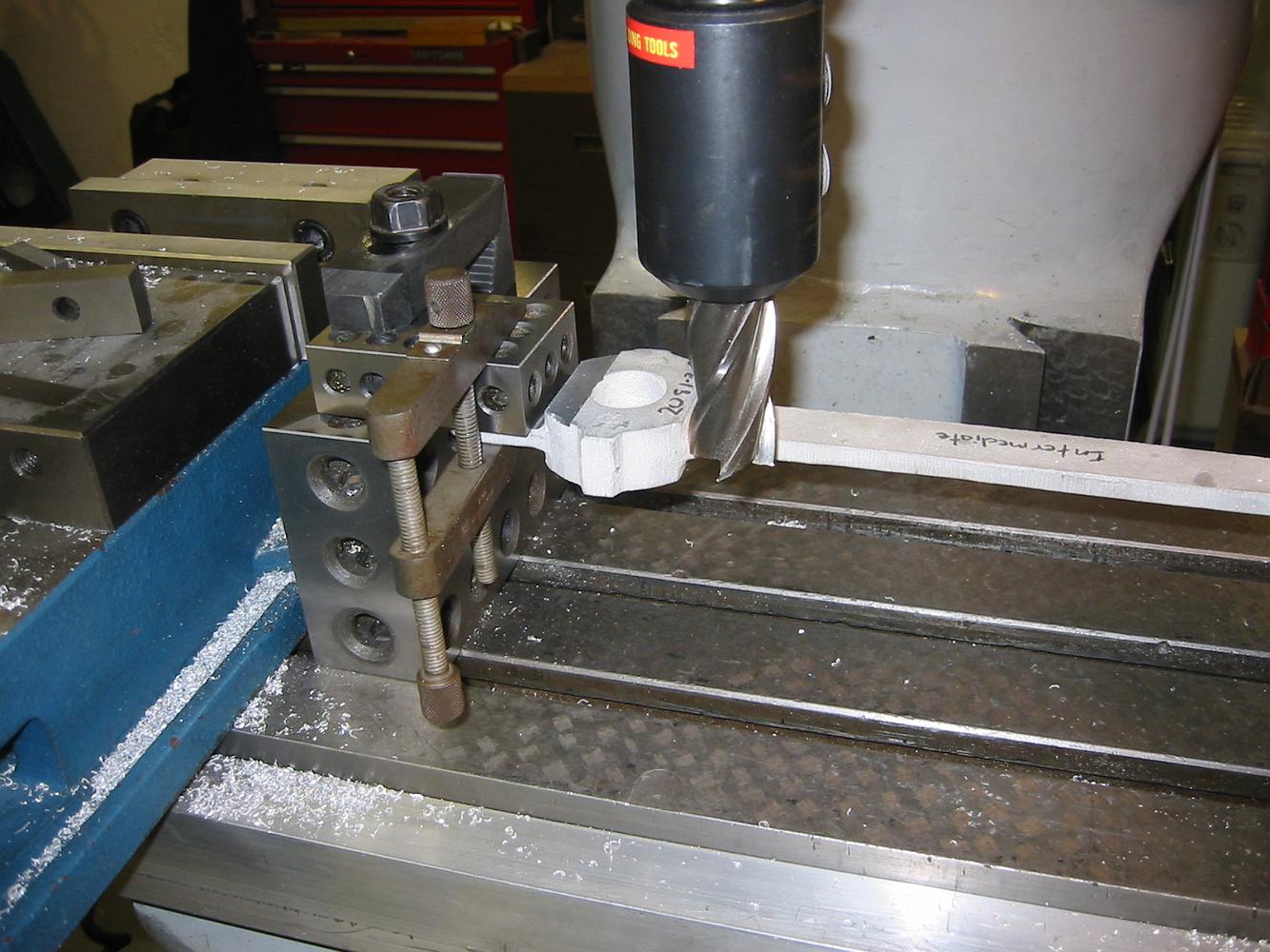
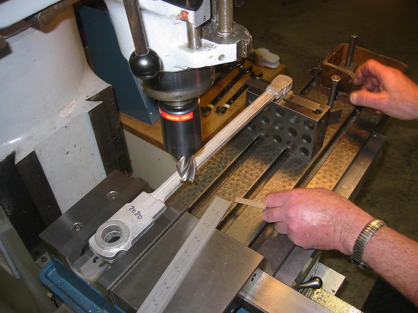
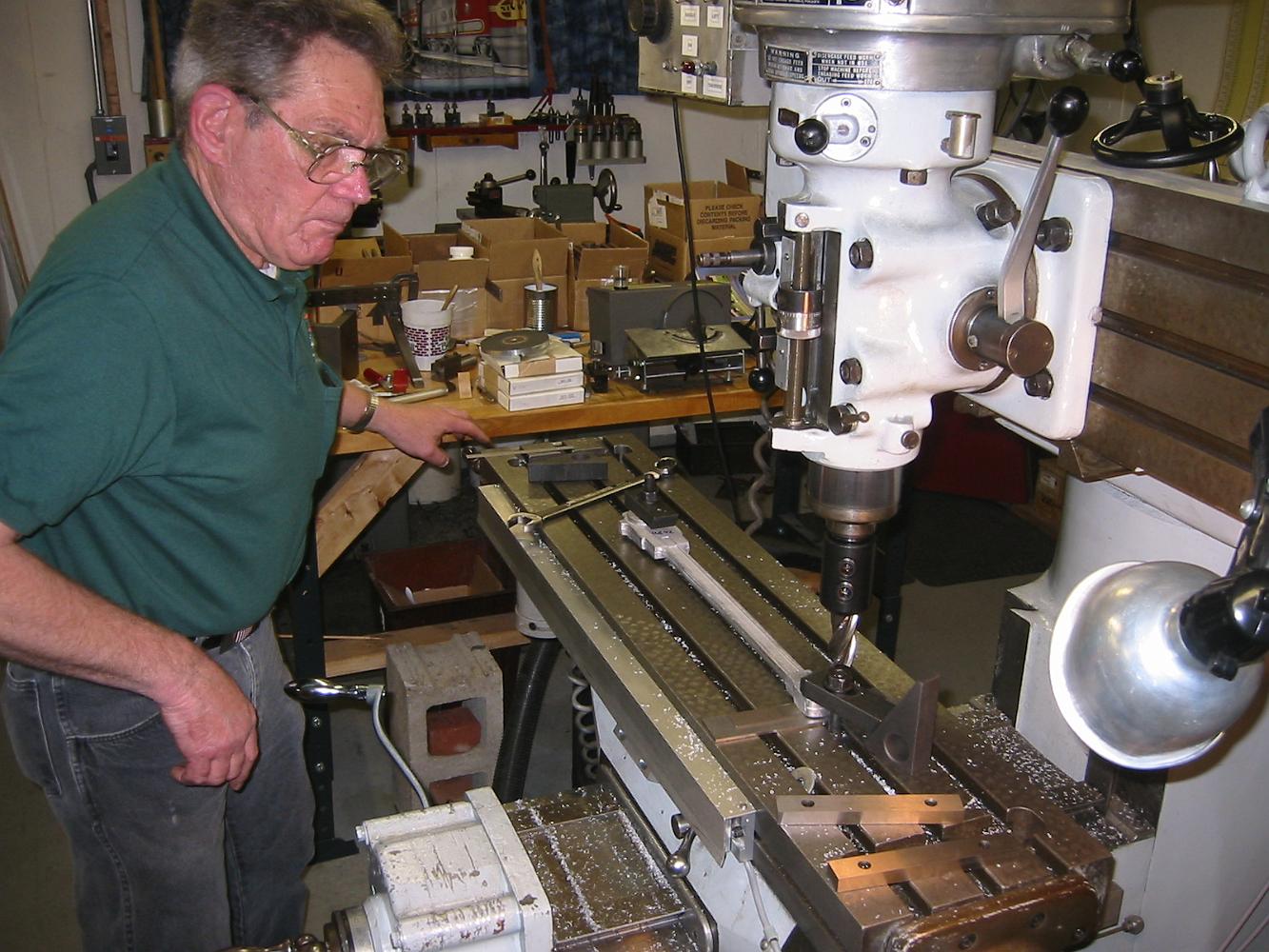
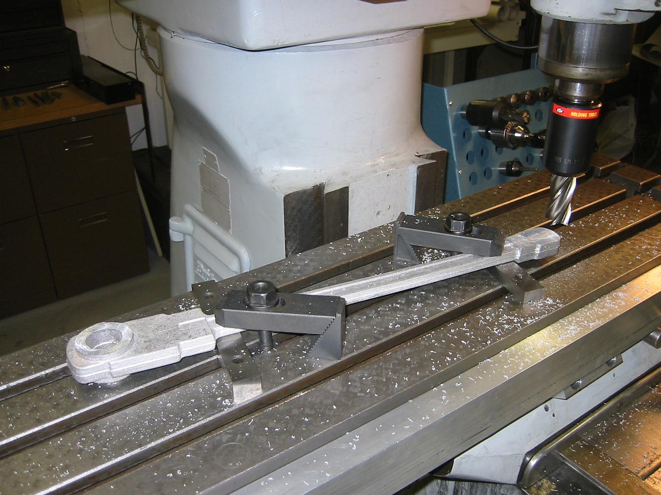
14-May-08 Drilling the holes in the intermediate rod. The left side is bolted down to the fixture, the right side is lightly clamped. We used a drill with…
The set up to drill the crosshead end of the main rod. The fixture is the same height as the parallel at the other end.
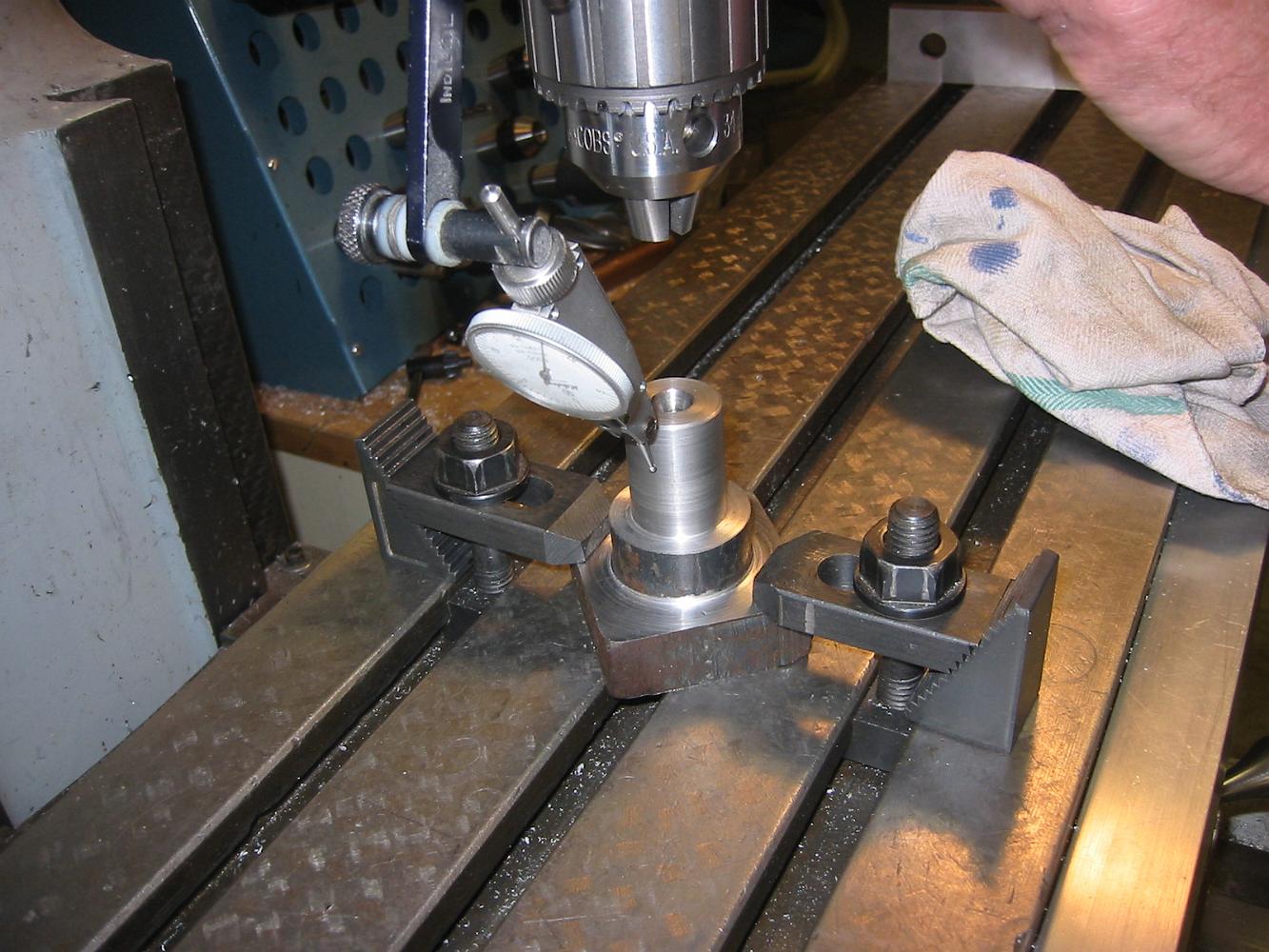
Having bolted the fixture to the table, we indicate all around to center and make sure it is perpendicular to the table. A minor adjustment to the Bridgeport…
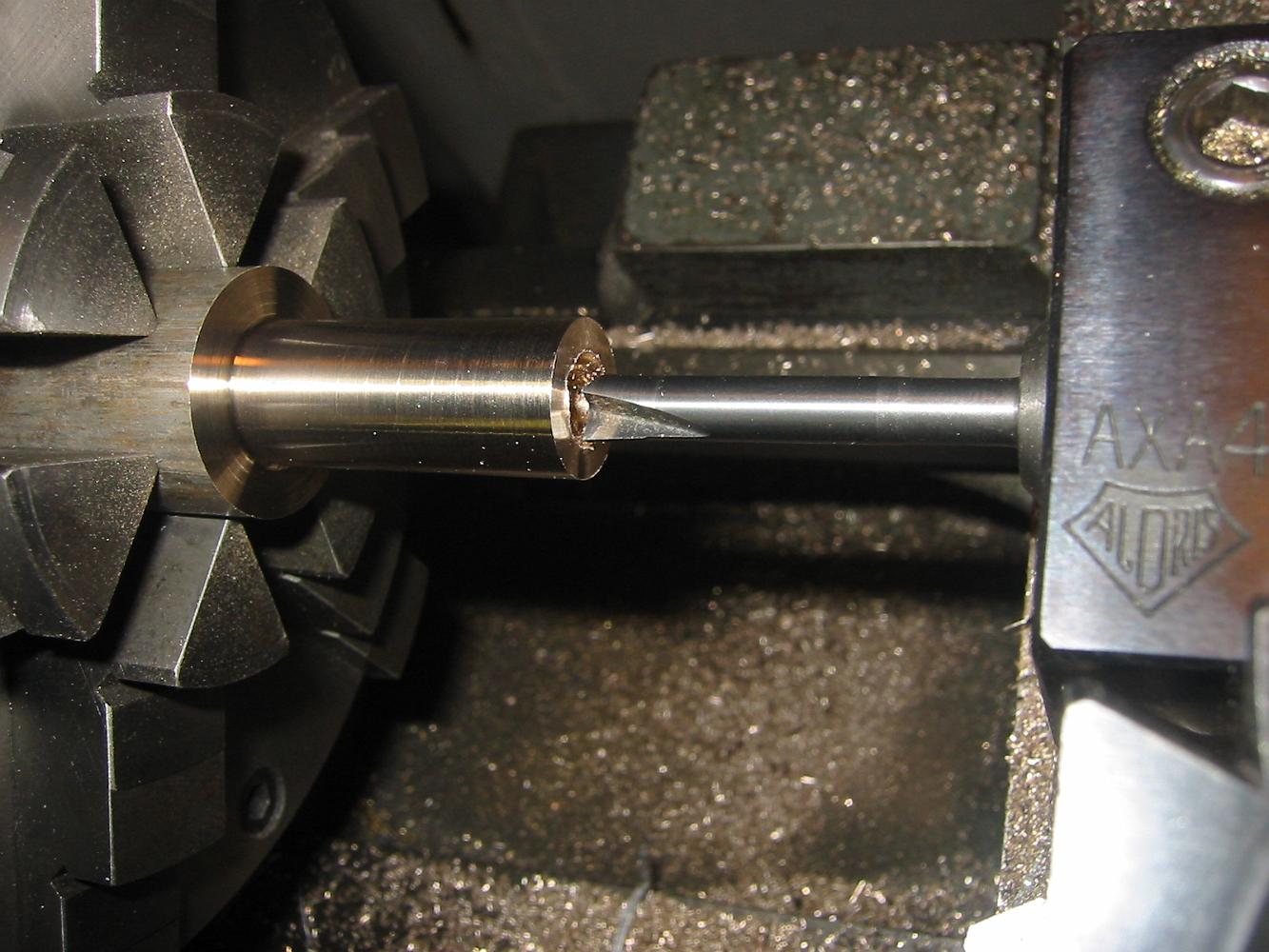
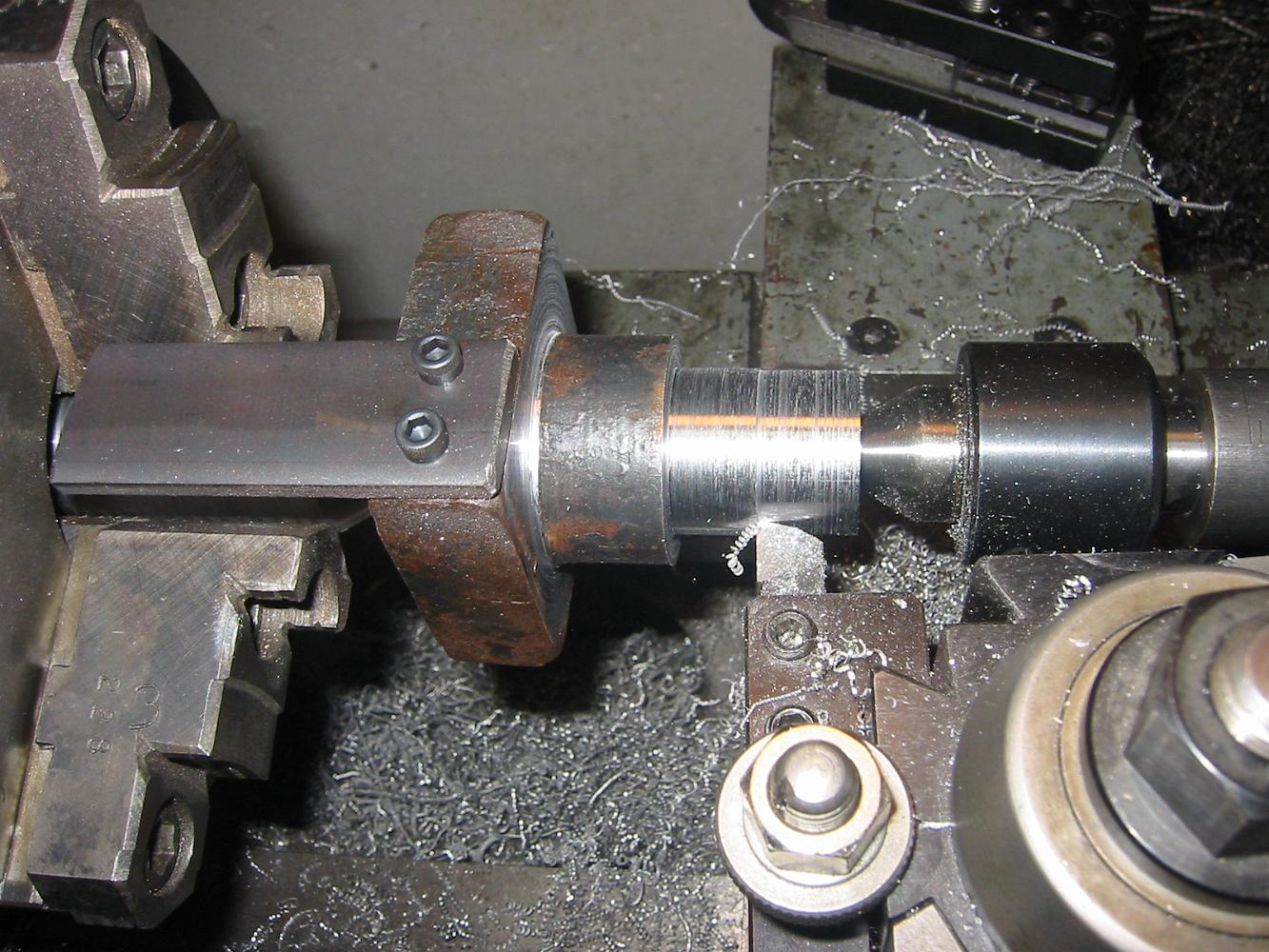
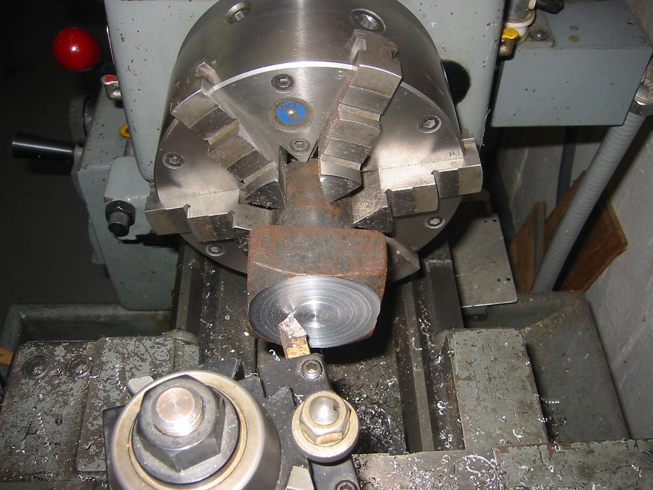
Having completed the facing operation, the bolt is turned around and centered in the 4-jaw chuck, the end faced, deeply center drilled and then center drilled…
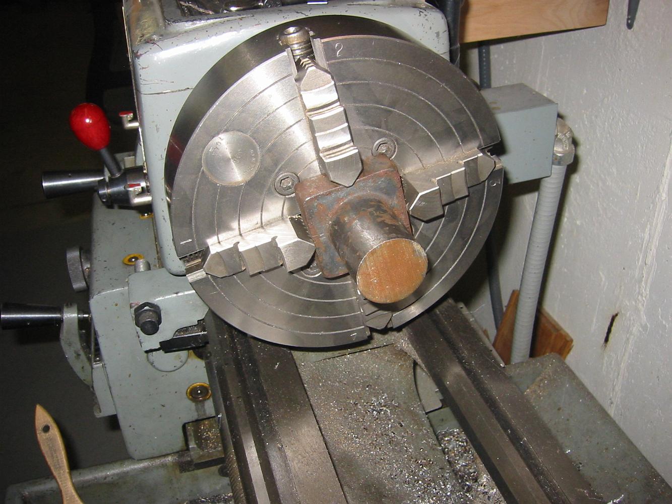
23-Apr-08 Turning an old bolt to make a holding fixture. First we turn the end flat since it will go down on the table.
23-Apr-08 Centering the connecting rod to bore the other end. We've moved the blueprint distance from the drilled end to the other end and are centering the…
Cutting the pressed in bearing to size. We later decided that cutting the bearing to size THEN pressing it in was a better approach.
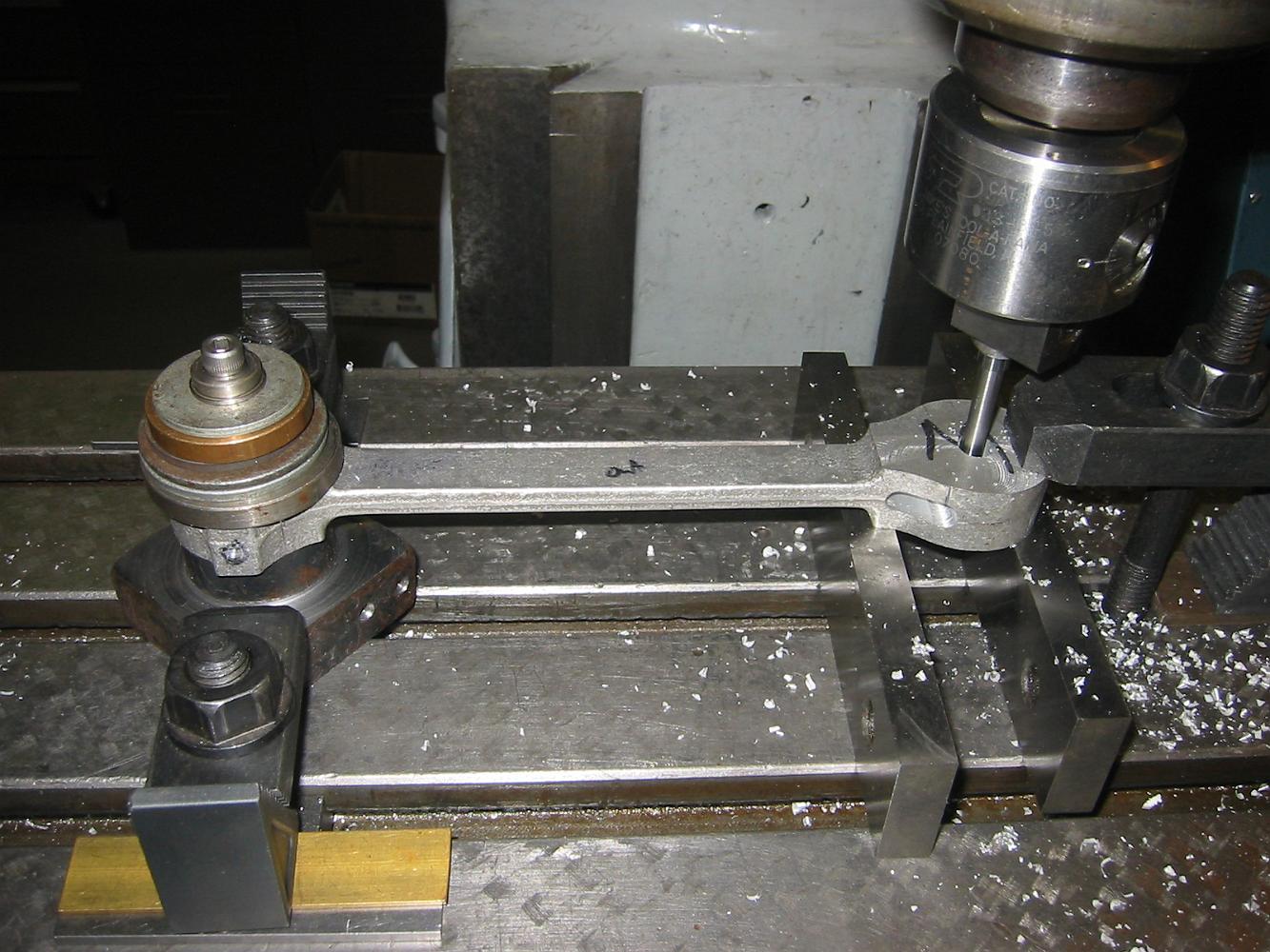
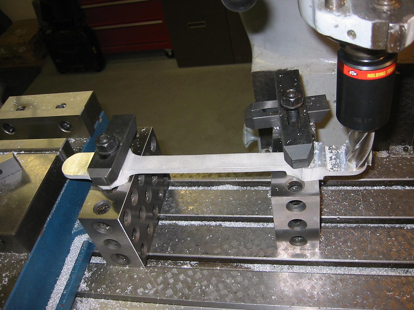
Here's what we ended up with: A very flat thick washer (brass in this case) on the table, lifting the rod off the table with clamps holding it tight.
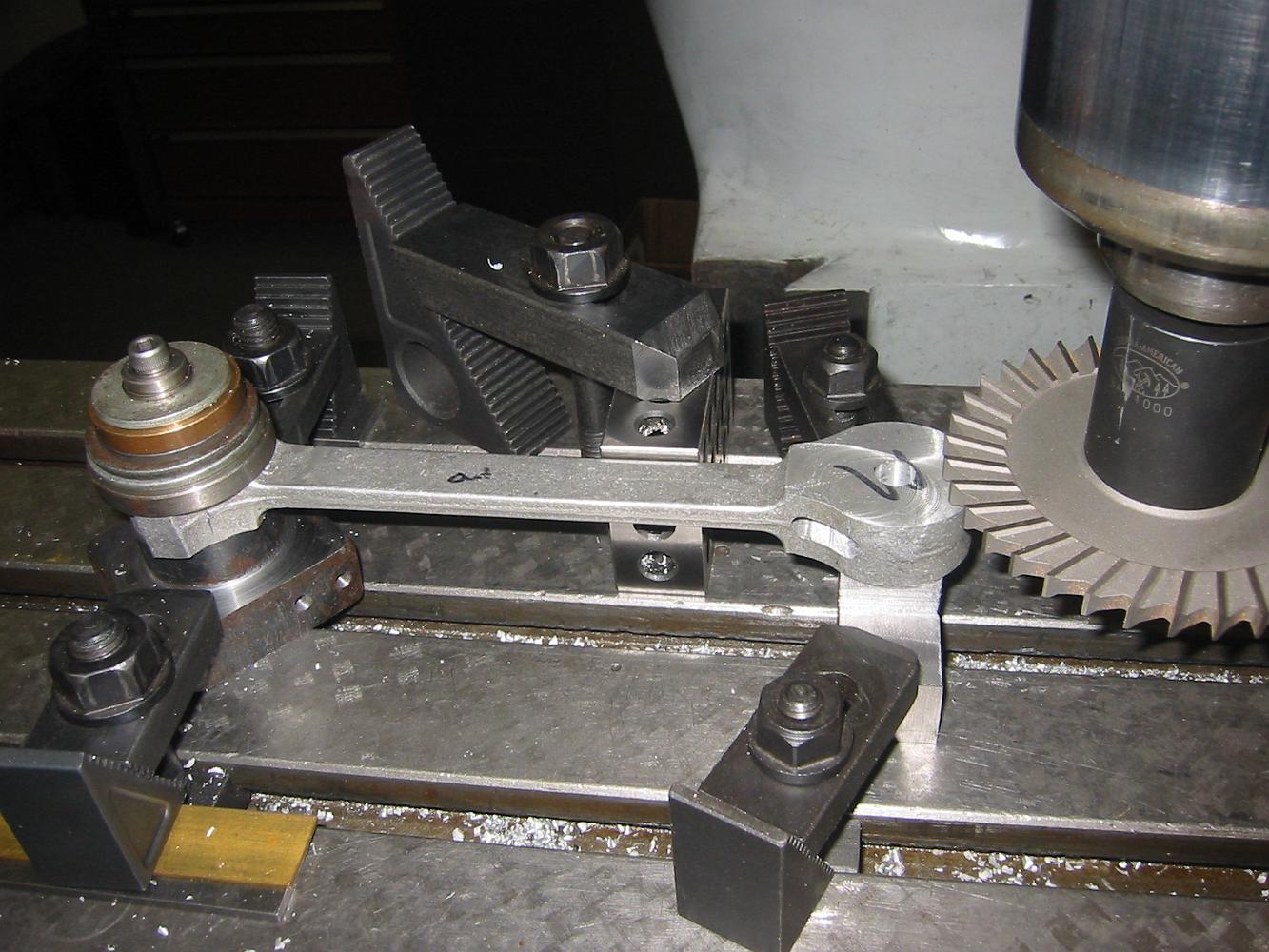
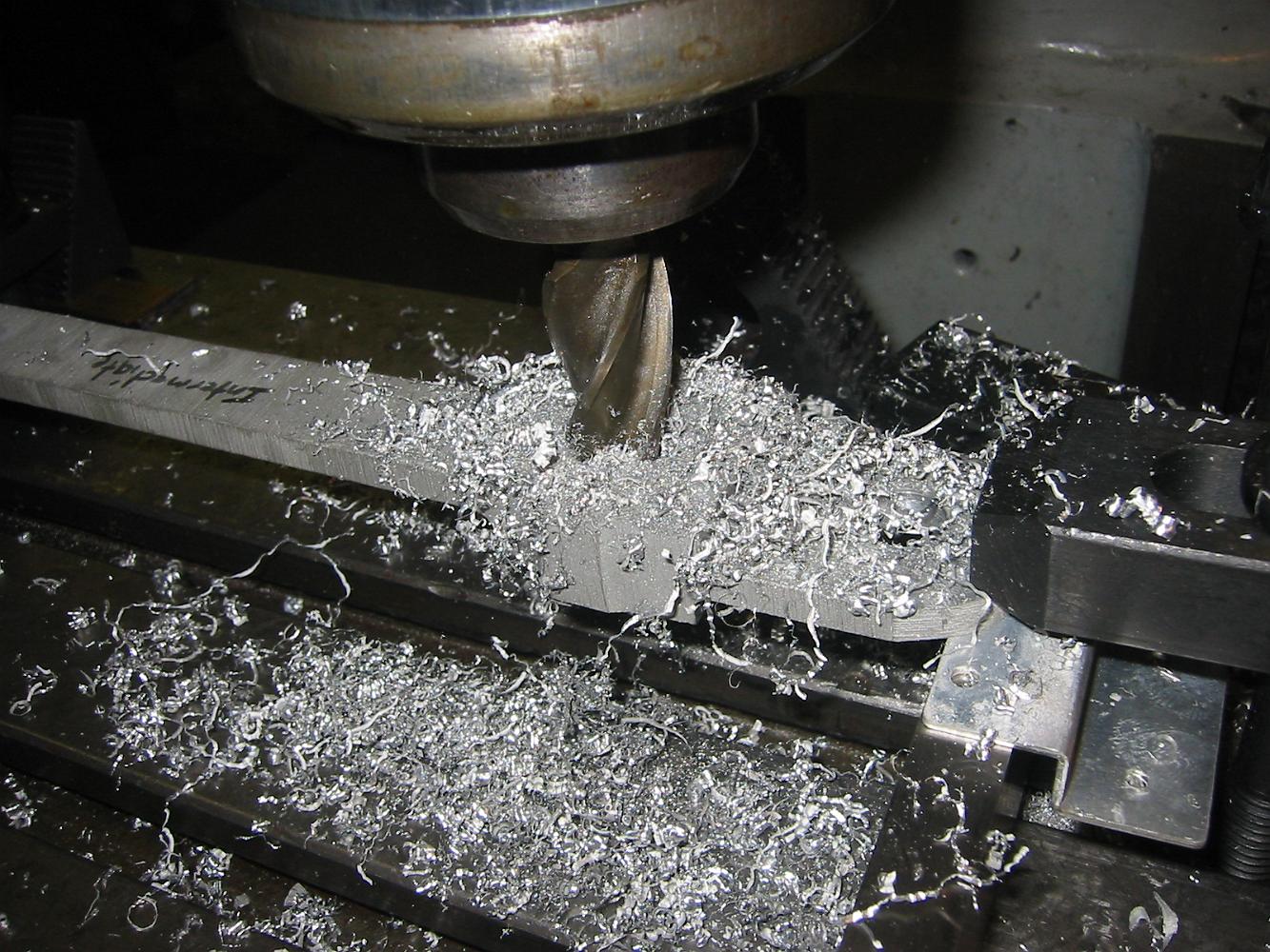
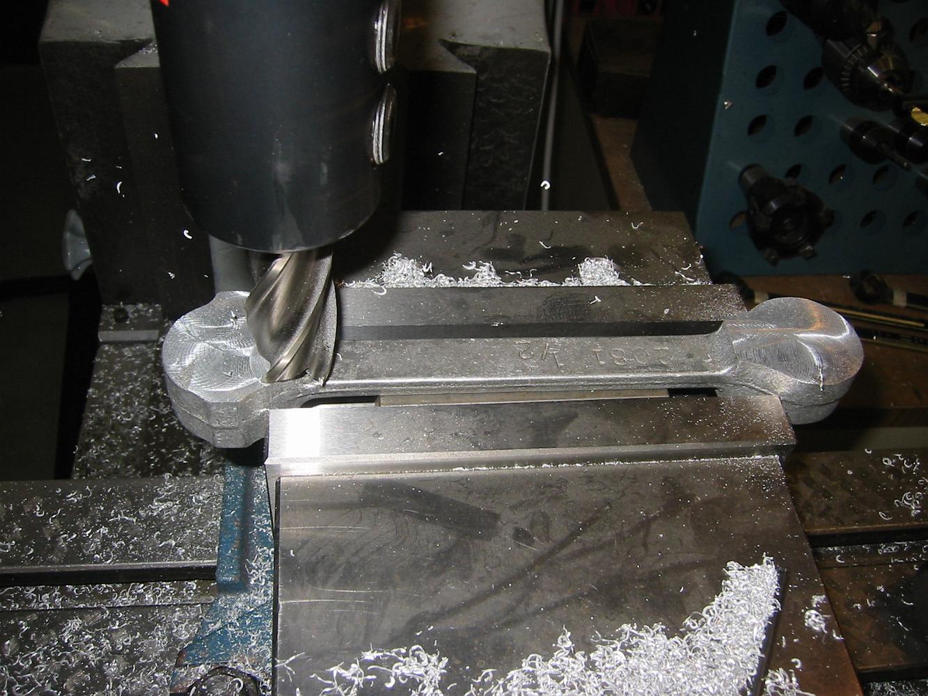
Milling the bearing ends to the finished size. This clamping solution turned out to be the best, the parts were solidly held to the table, without introducing…
Previous clamping attempts did not work. We needed a way to hold the bearing ends of the rod down to the table which allowed us to machine the very same spot at…
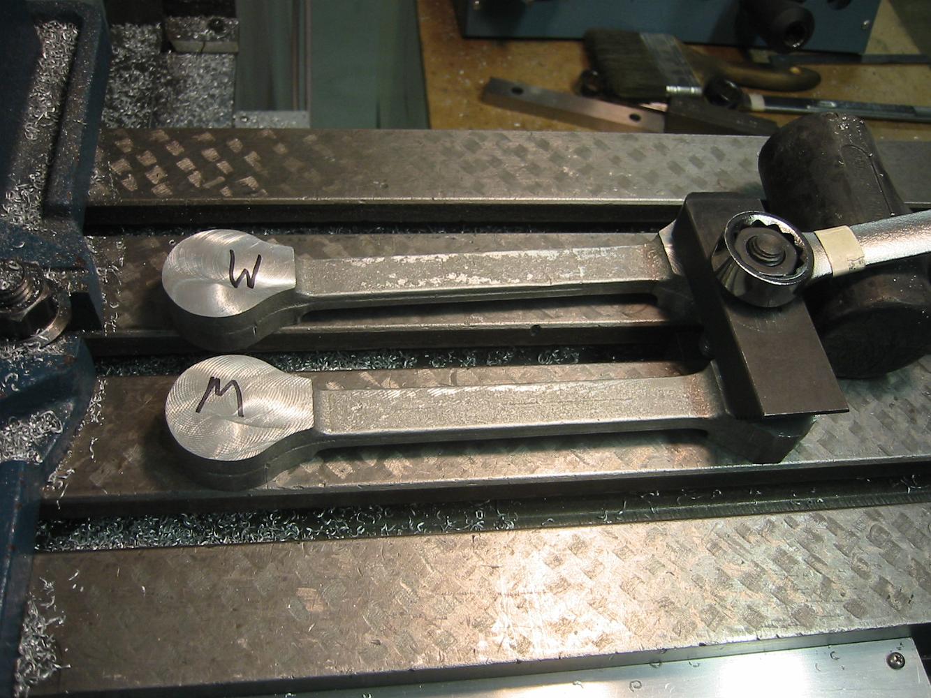
With the one machined side down on the table, we try to clamp them down to machine the other side. The "M" written on the part indicates the to be machined…
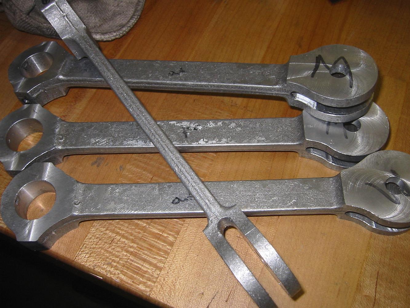
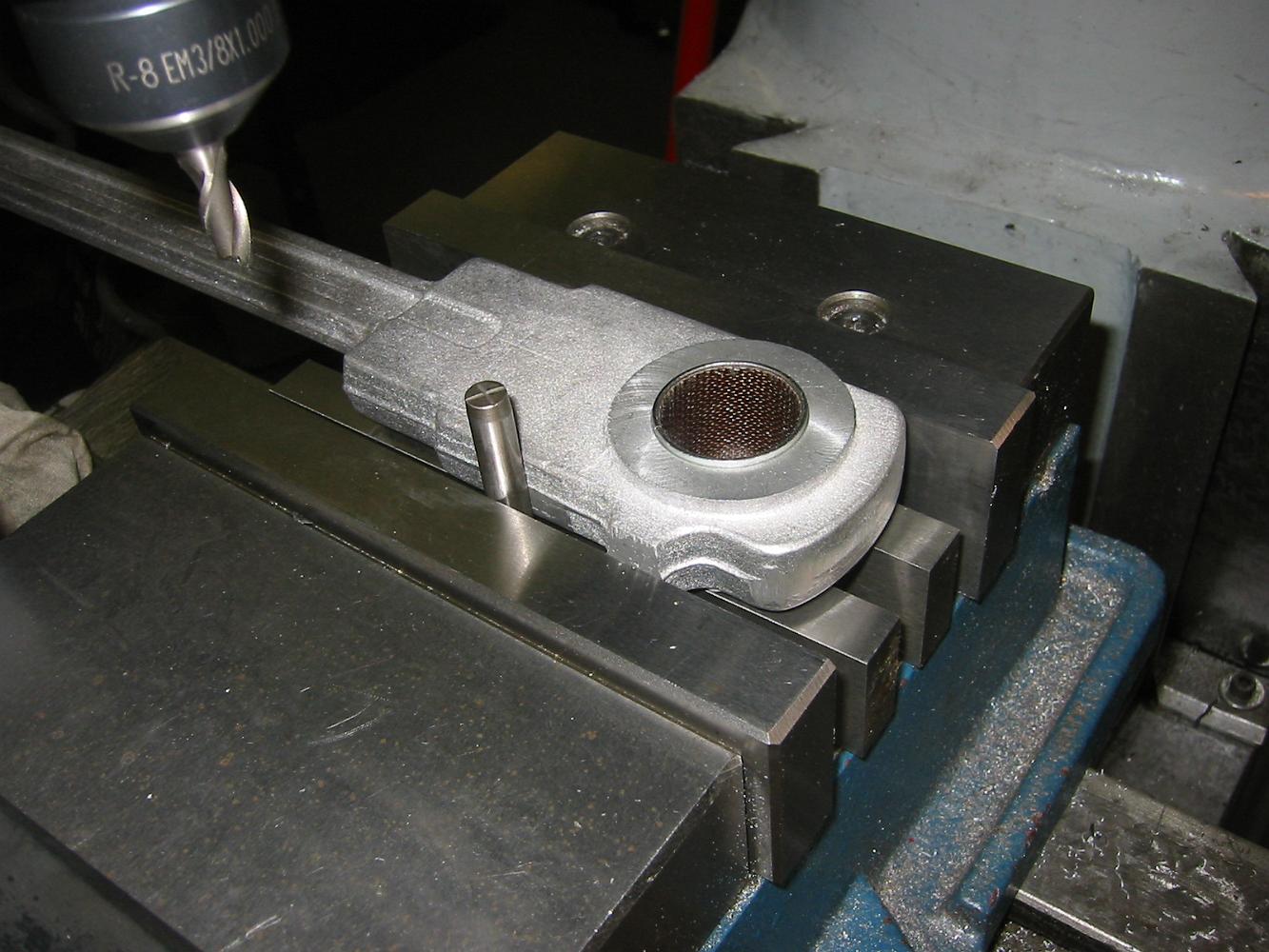
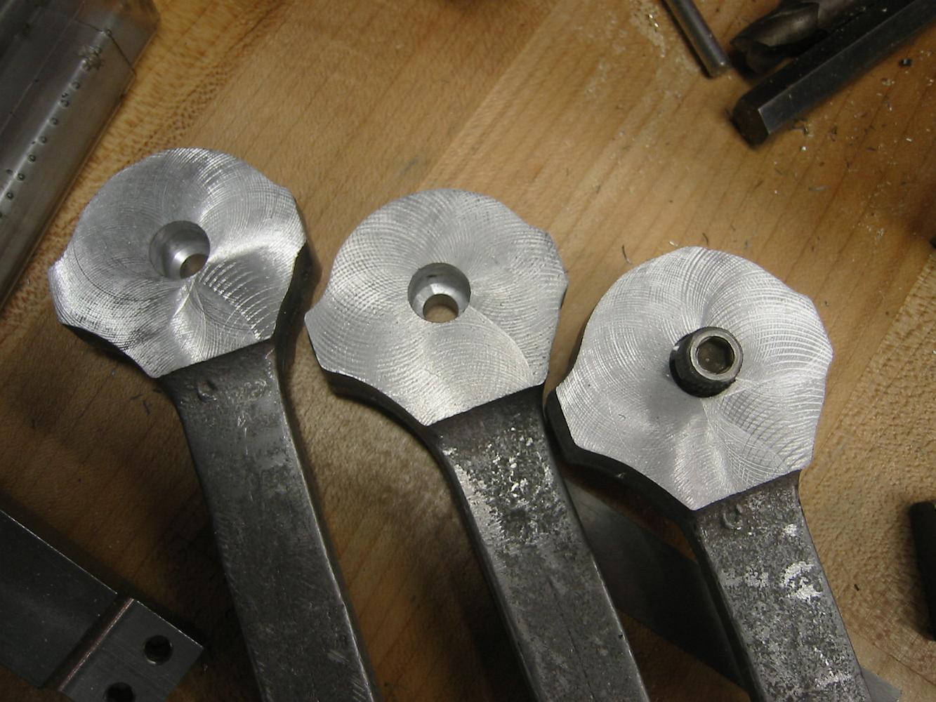
2-Apr-08 On to the side rods. Another set of castings, more challenges. Where to start? Using the center web as a rough guide, we clamp the rods on the vice and…
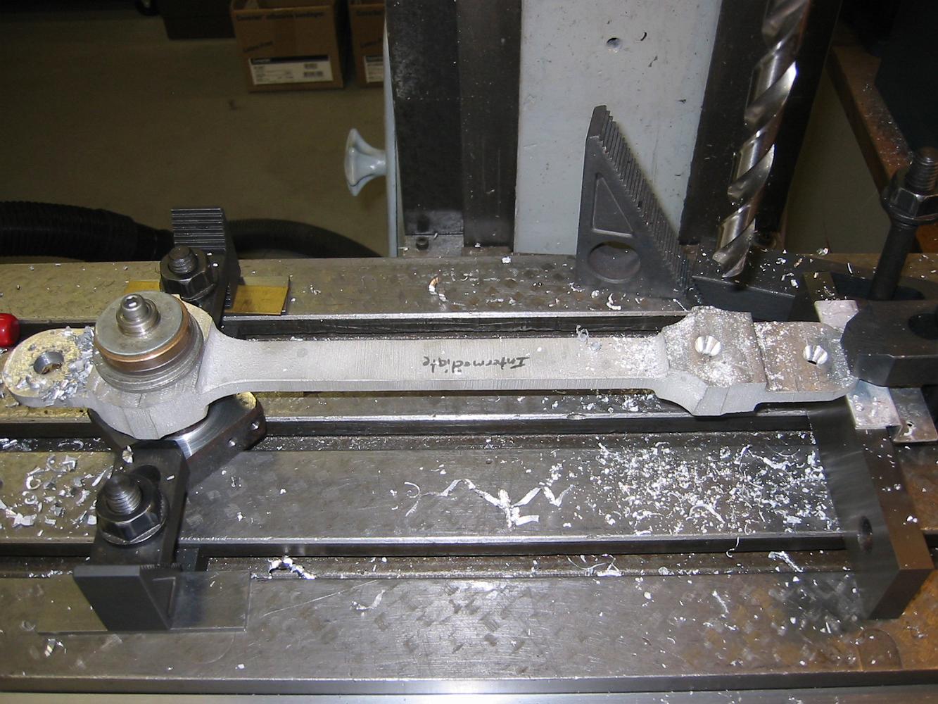
26-Mar-08. The Intermediate Drive Rods are another pair of challenging castings. The thin tabs at either end were warped and there was a twist between either…
11-Mar-08 We start a new Section! Like all castings, the question is where to start - nothing is smooth or straight.