August 15, 2007, we start section 8! Machining the Link Support brackets which will bolt onto the frame.
We machined the bottom first to give a reference surface for the remaining operations.
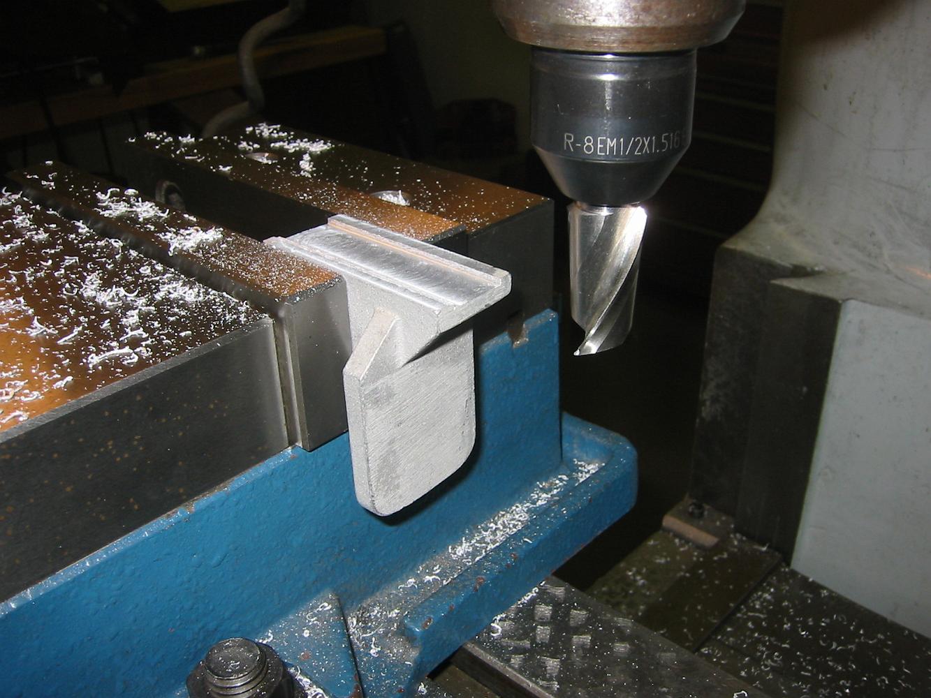
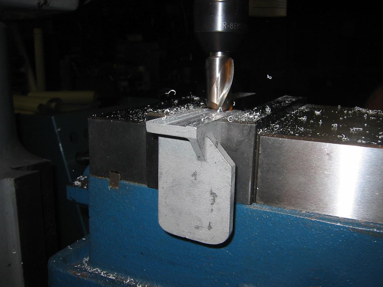
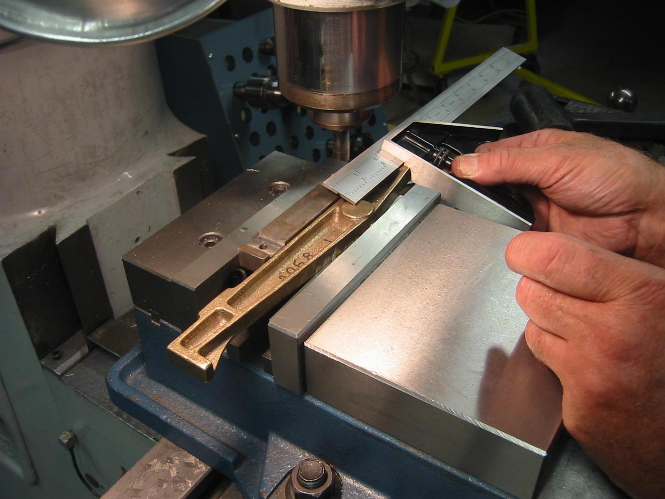
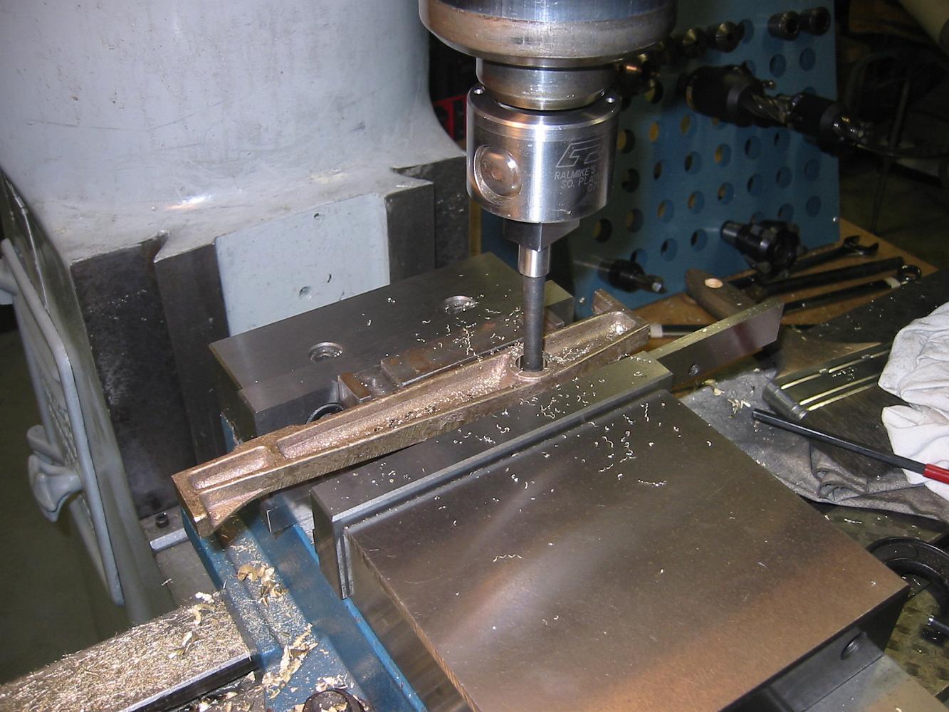
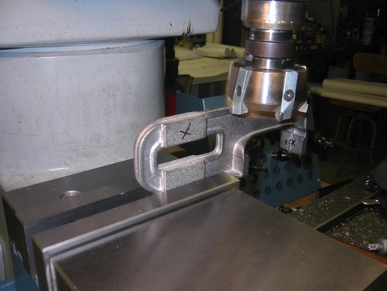
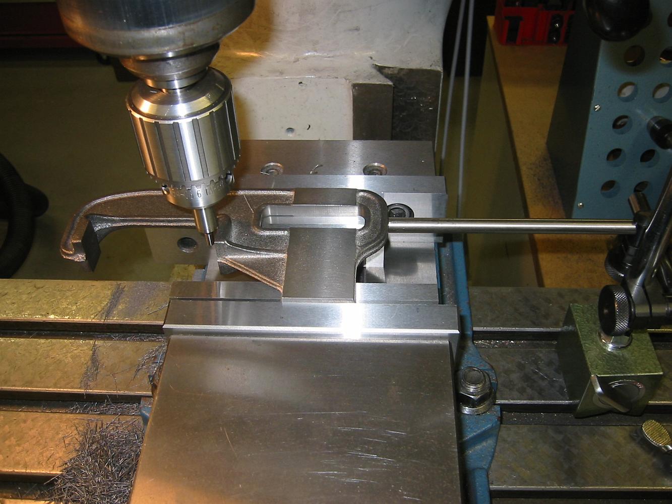
Using the angle plate, which fortunately is slightly smaller than the locomotive frame we have to bolt the link support bracket to, we hold the bracket square…
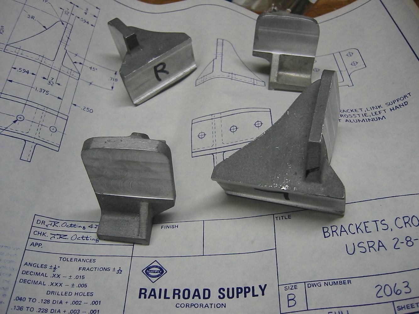
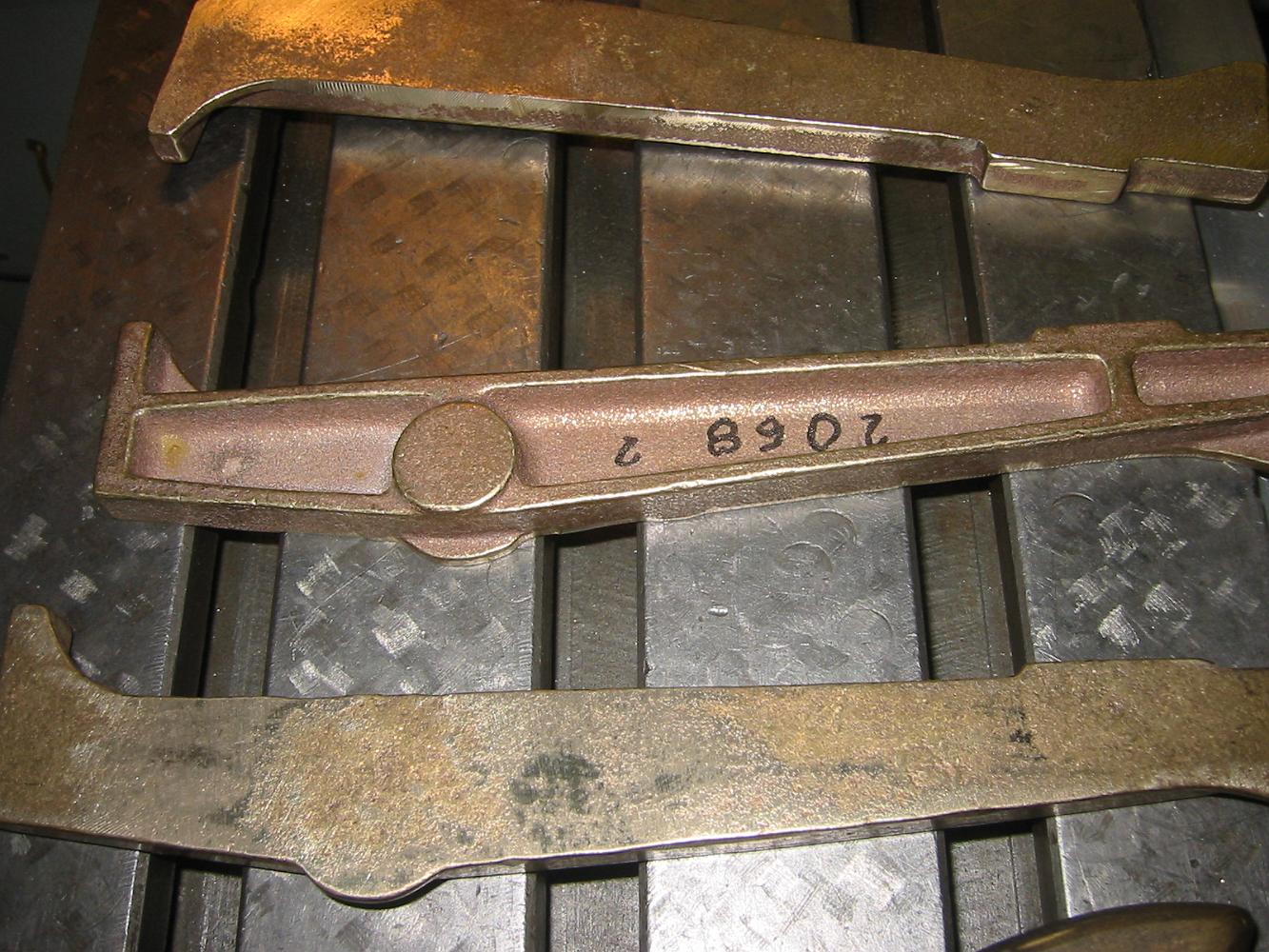
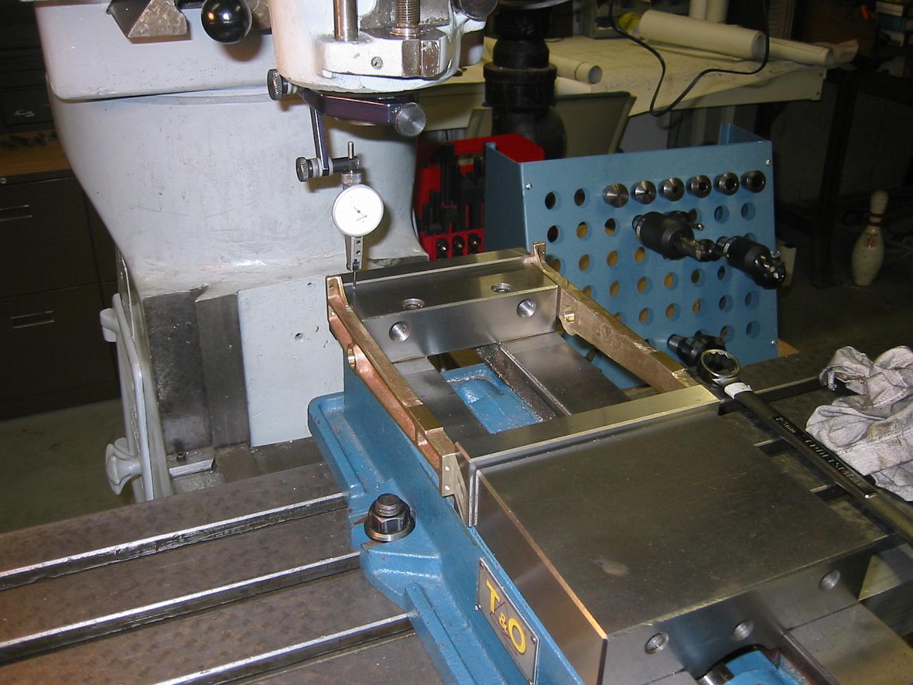
The crosstie brackets awaiting holes, next week.
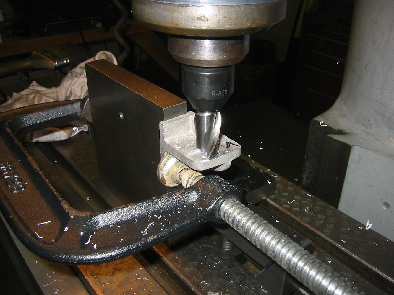
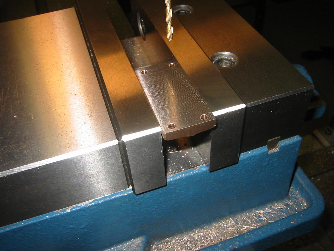
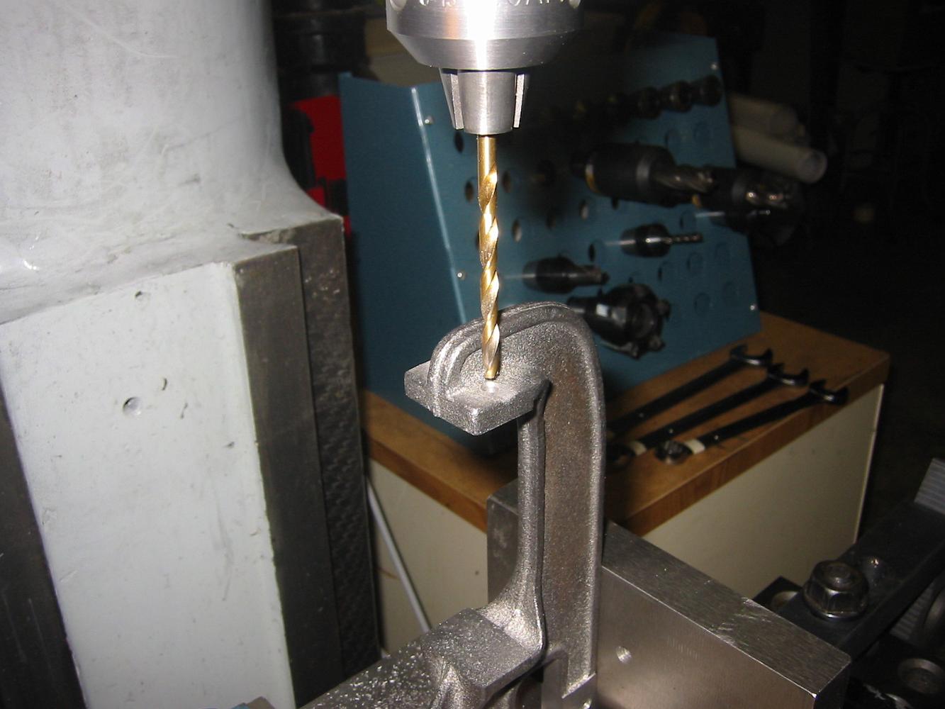
22-Aug-07 Drilling the mounting holes.
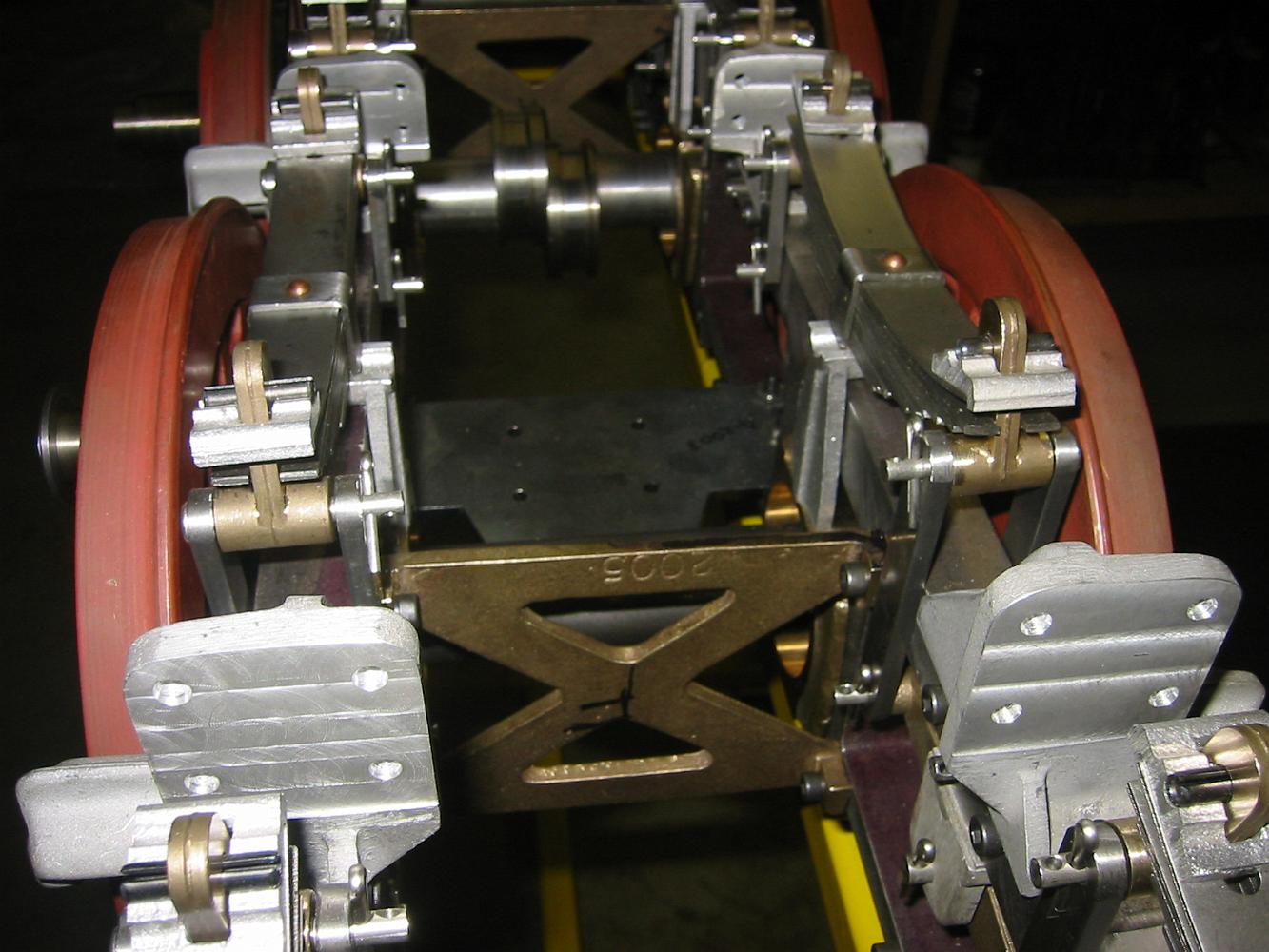
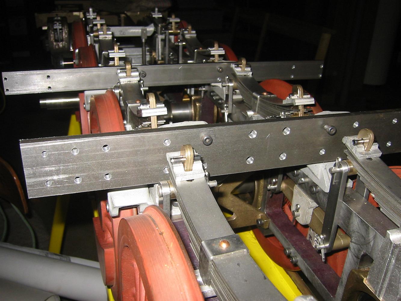
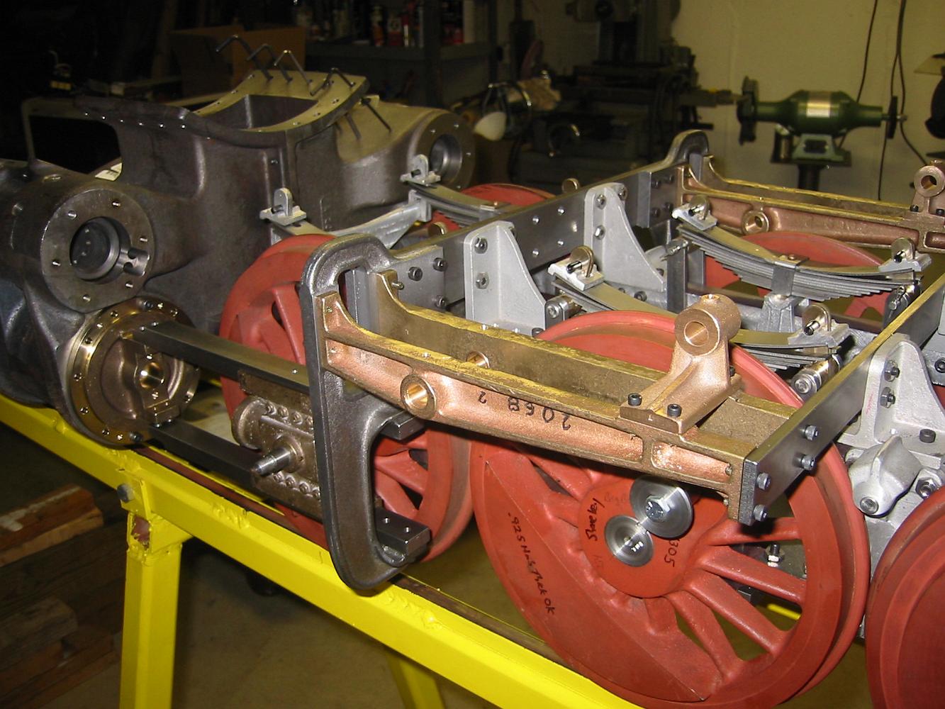
The finished link support brackets installed on the frame. Hey! These parts only took two shop sessions, that was pretty quick!
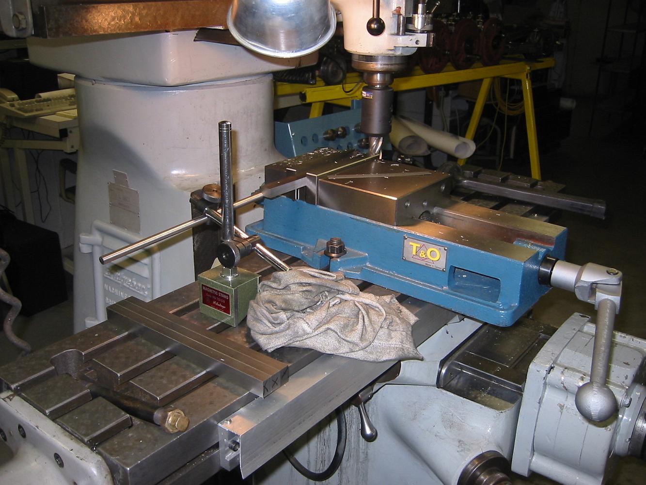
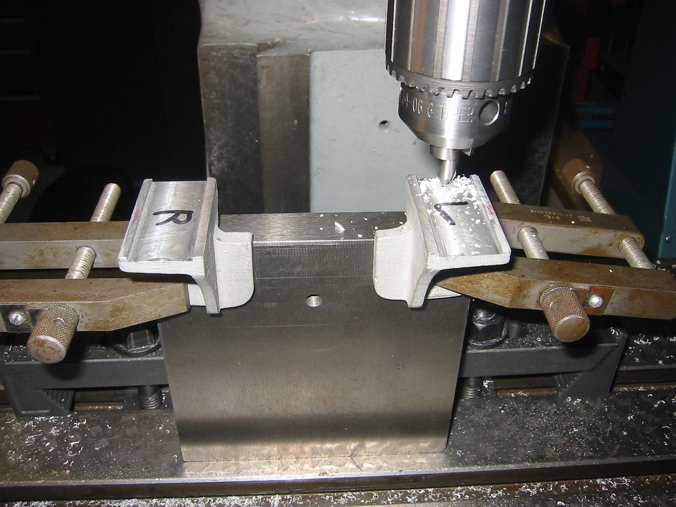
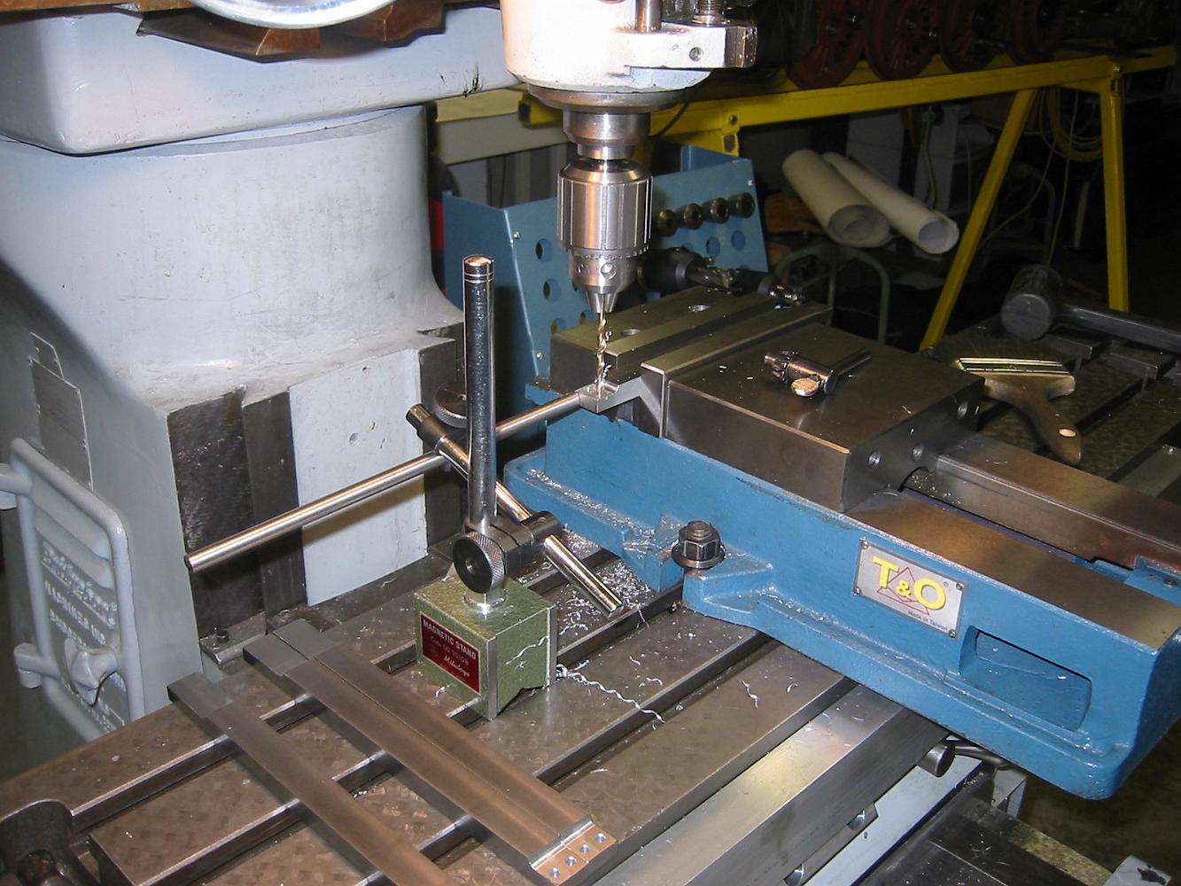
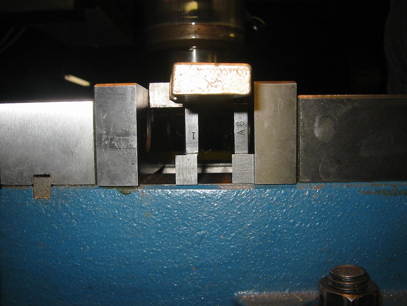
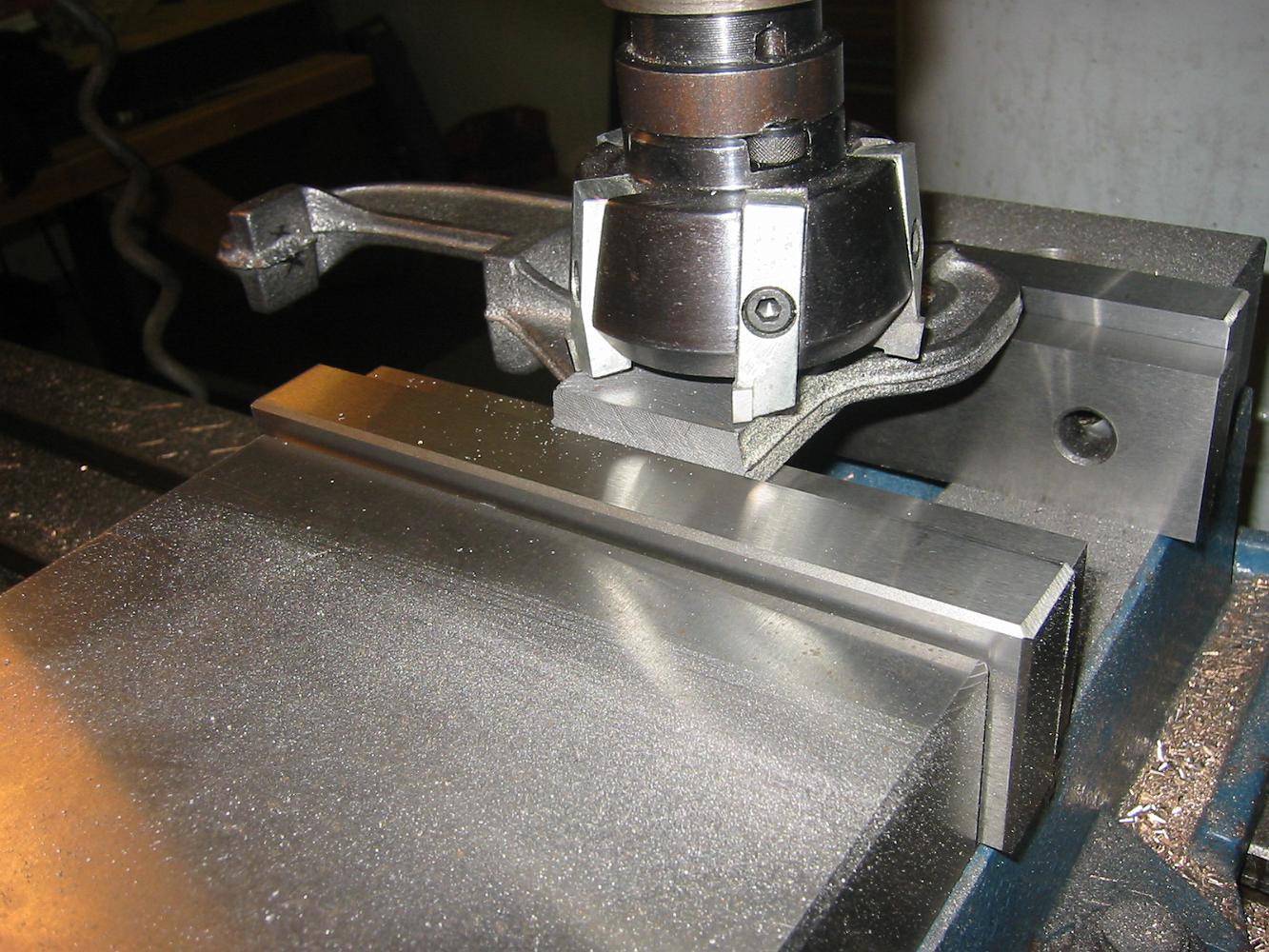
29-Aug-07 With fresh 3/4" x 1/2" bar stock in the vice, we prepare to 'mass produce' four crosshead guide bars. Using a magnetic base as a vise stop, we only…
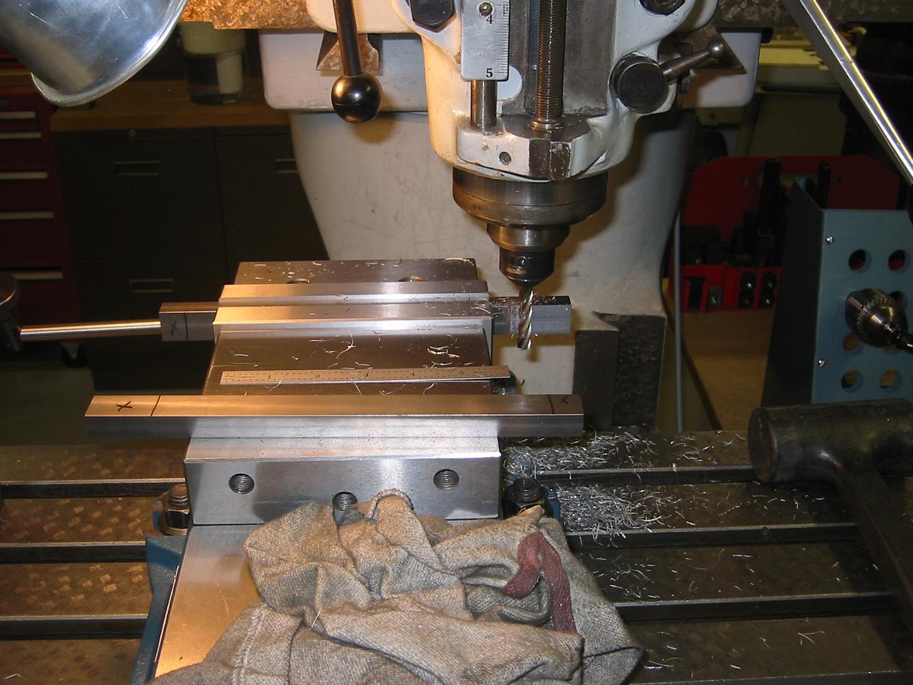
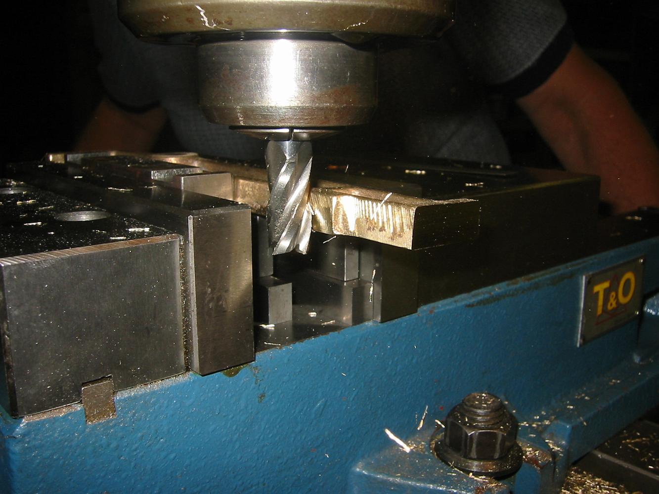
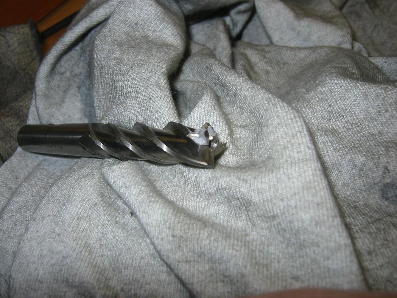
Side milling a relief as called for on the drawing. Shortly afterward, Bill said "I think the cutter has lost its edge, it is dragging a lot more." And two…
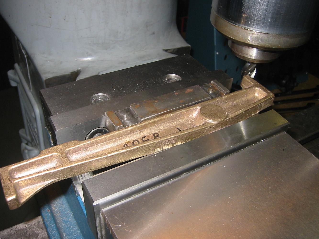
Drilling the mounting holes.
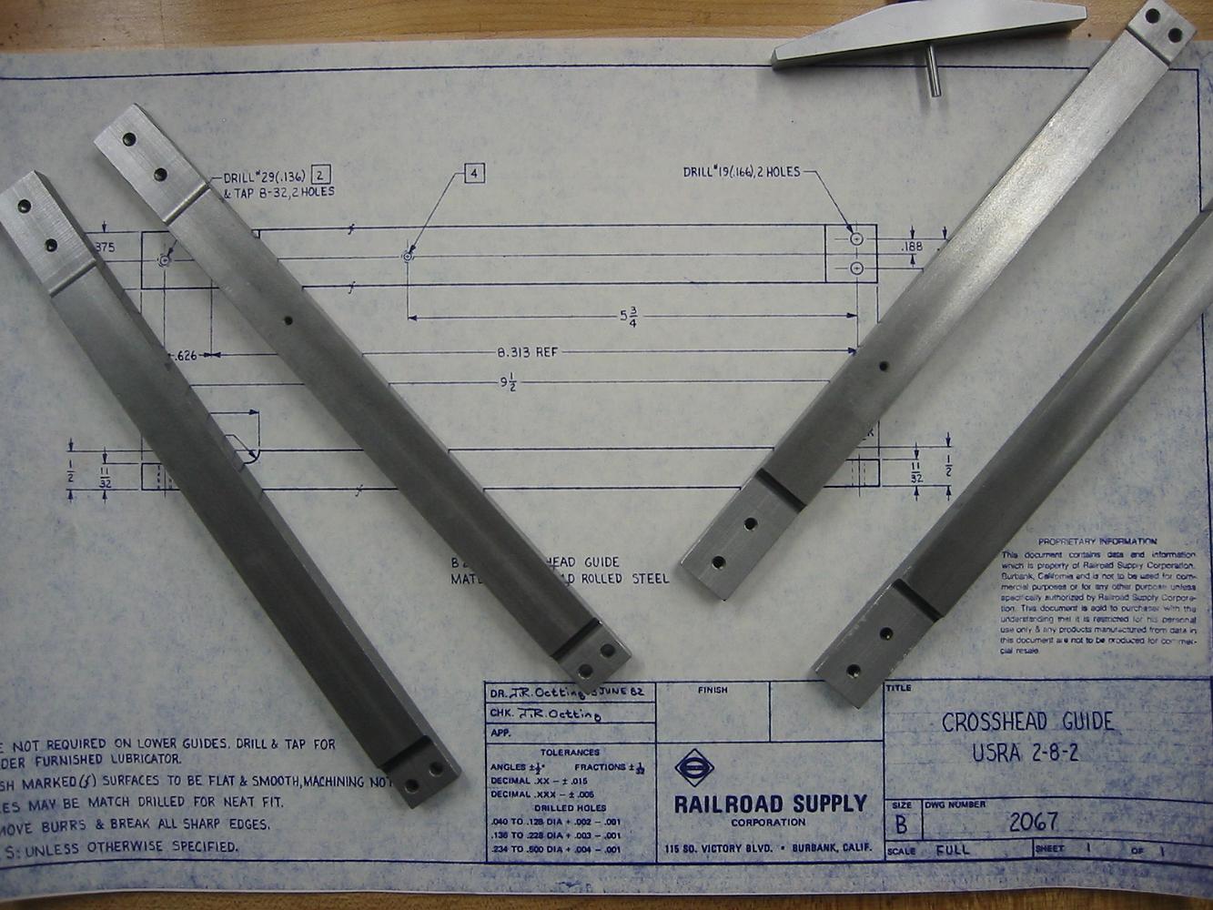
The finished Crosshead Guide bars. The little hole in two of the bars is for a lubricator line connection.
Labor day weekend I fabricate the front and rear Link Support braces. A nice, simple, mark and drill operation.
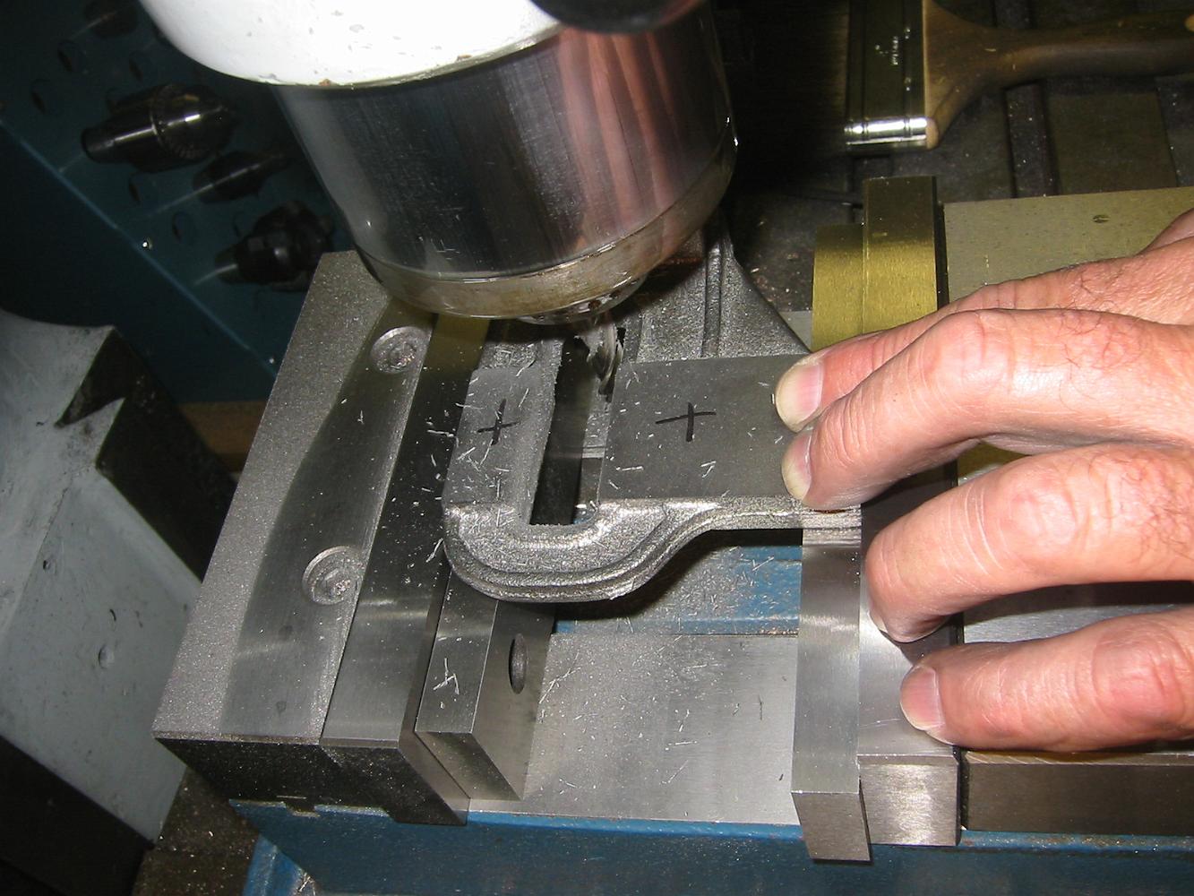
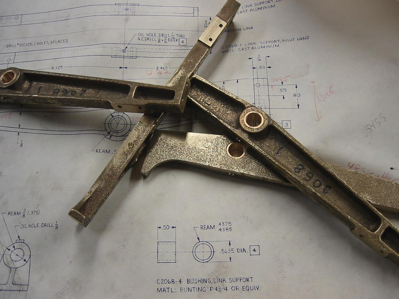
5-Sept-07 We begin work on the Link Supports. The is so little machined surface to reference from on these parts, yet they have to finished to length and a…
The prints did not call for the inside (bottom in this view) to be finished, so we worked on them with files and sandpaper to get them reasonably flat to put in…
After (top) and before we worked on the inside of the castings.
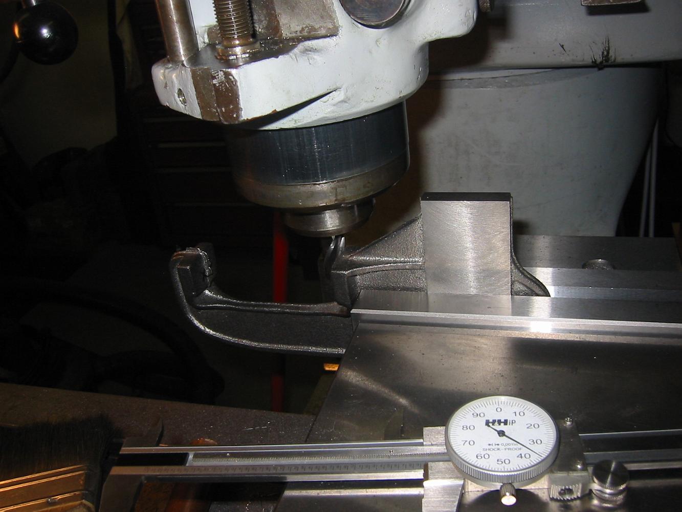
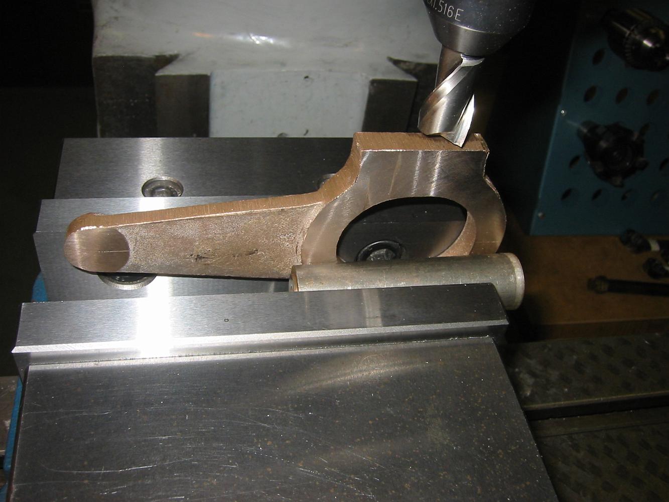
Checking the relative position of the through hole after machining some off the end. Since you do not start with any reference or location points with a…
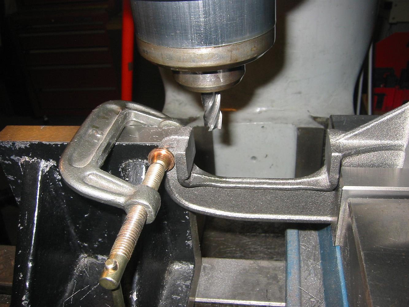
Machining the Pillow Block base in the same clamping.
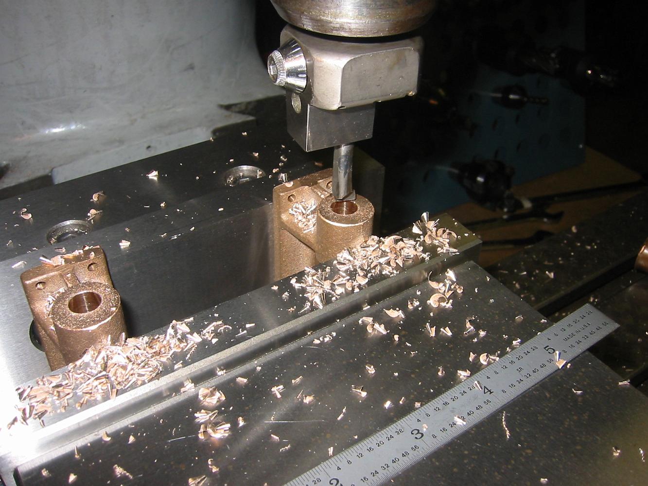
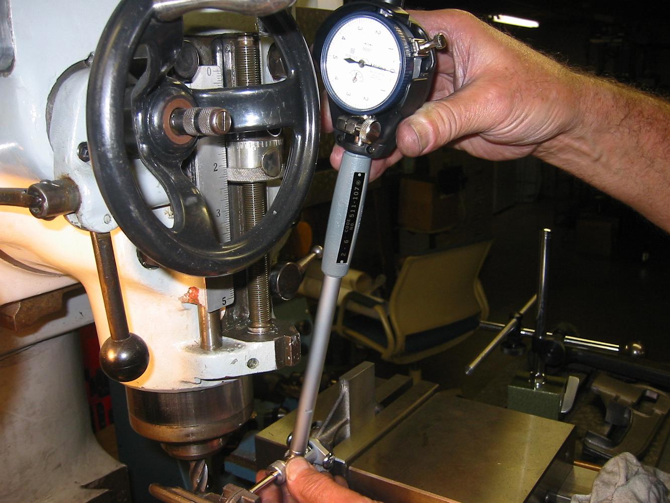
After drilling, we bore the through hole for the bushing, since I do not have a 9/16" reamer.
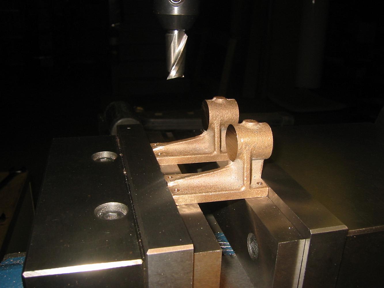
25-Sept-07 Work on the tumbler shaft pillow blocks has begun.
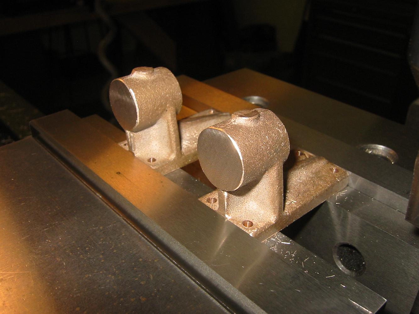
Match - Machining the blocks for uniformity.
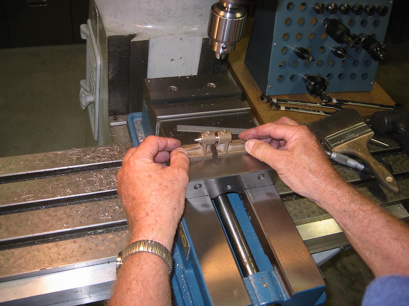
Using a single pin in both bores to check the parallelism of the two pillow blocks. Since a single shaft will have to turn in both parts, having the bores…
10-Oct-07 Work on the cast iron Crosshead Guide Yokes is begun, after much study of the drawing, the reference lines and the casting. The surfaces to be…
Once the inside and outside, or in this orientation, the front and back surfaces are machined to size, they are used to clamp the part square in the vice.…
Lacking either the proper clamping tools, or imagination, the angle plate and c clamp is used to secure the lower jaw and minimize the chatter the clamping…
Using a vice stop (on right) to speed setup time for the repeat operations for these two parts. After clamping the second part, the edge finder is used to…
15-Oct-07 Finishing the Crosshead guide yoke. Although the first holes were easy, the same holes on the bottom (of the picture) were more of a challenge, since…
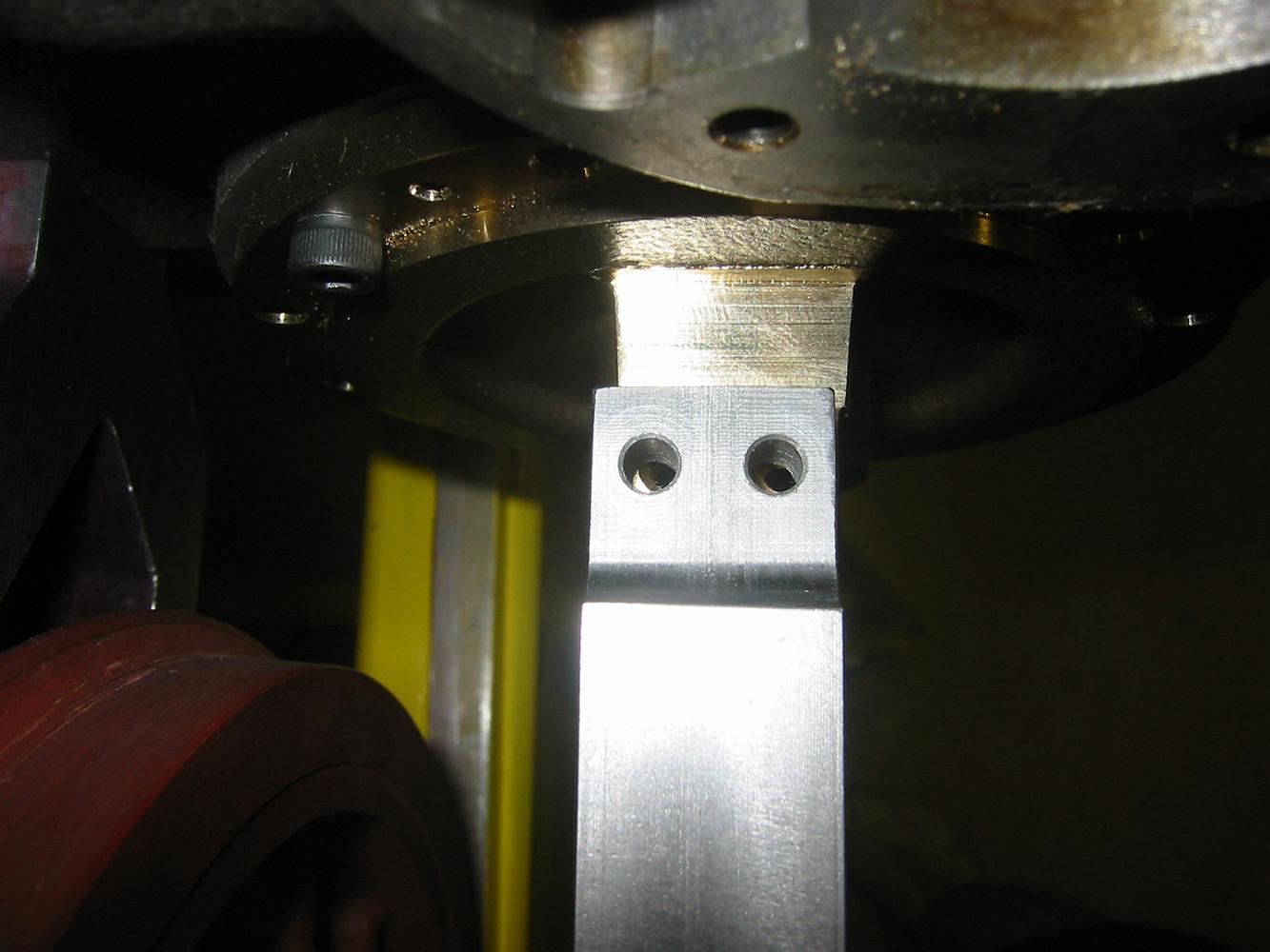
16-Oct-07 Hmm. There is supposed to be a 1/16th of an inch gap on the top and bottom crosshead guide bars. Why is there no gap on the top and 1/8th on the…
Uh Oh. Those holes are supposed to line up with each other. We spend the next two hours going over the blueprints of various parts, measuring and checking them…
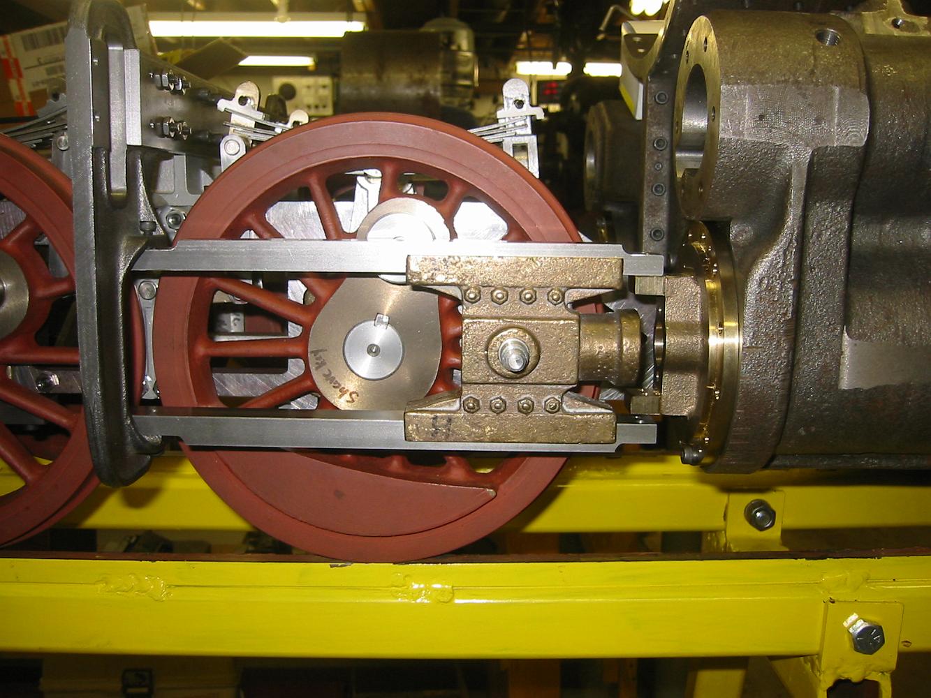
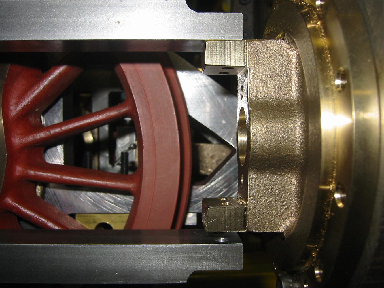
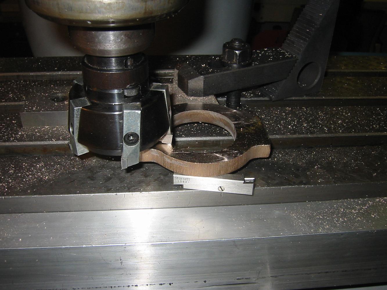
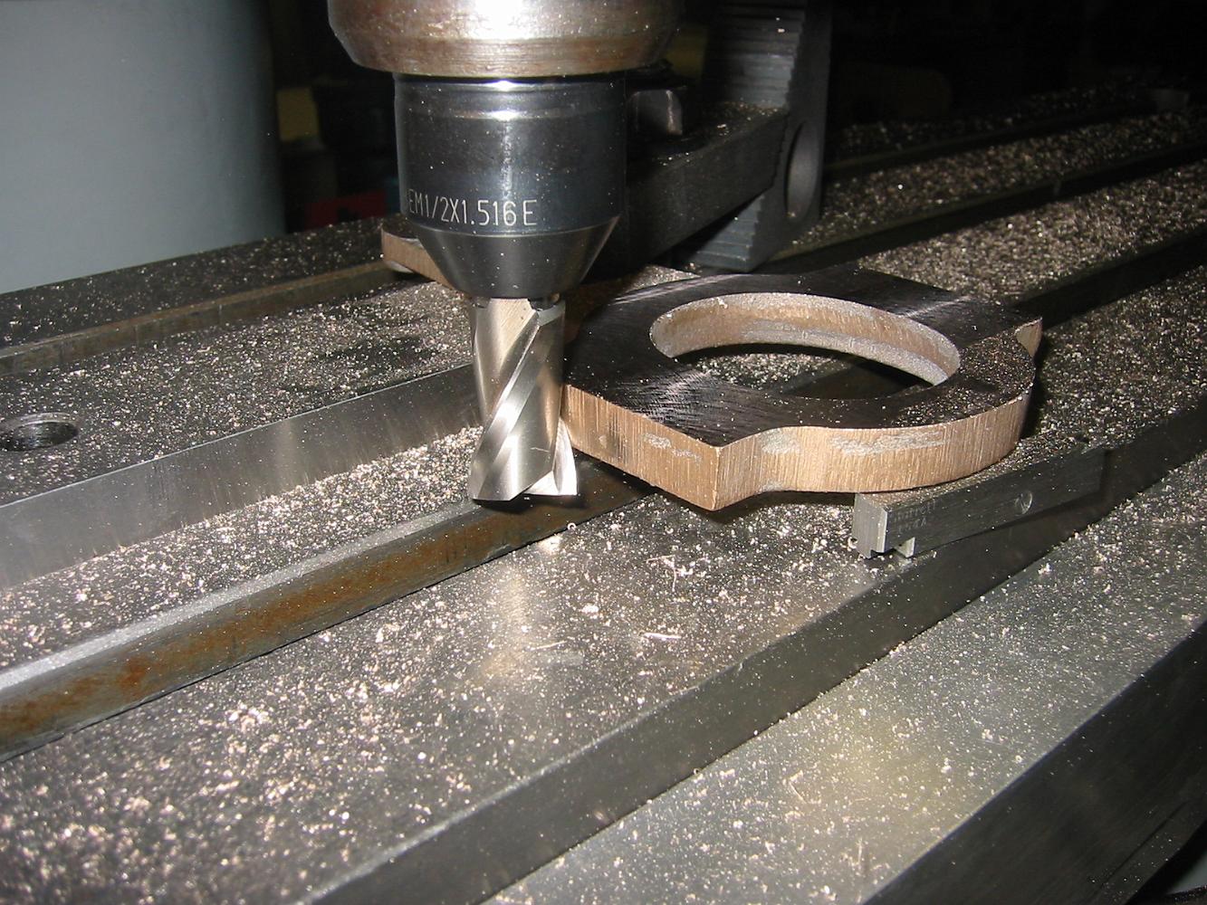
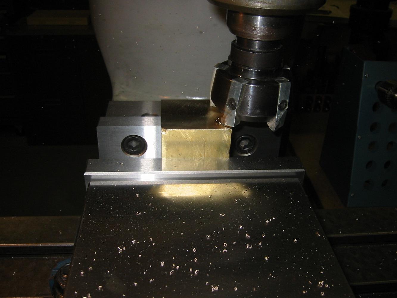
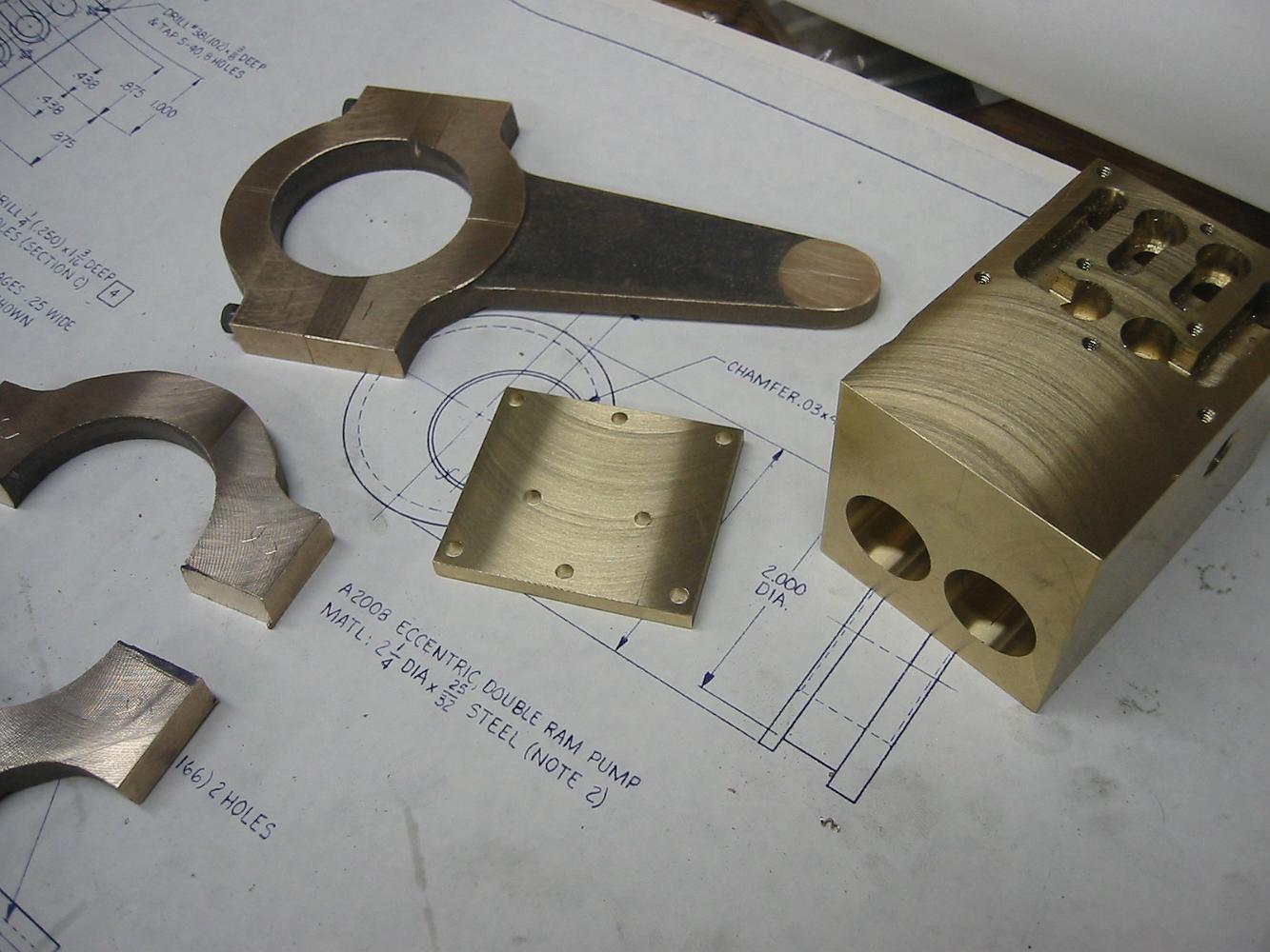
7-Nov-07 We set the frames aside and start on the water pump. Face milling the eccentric. These castings are hard to hang onto when you first start the…
Machining the other side doing our best to keep the part centered. You can see how much of the boss we had to machine away on the left during the face milling…
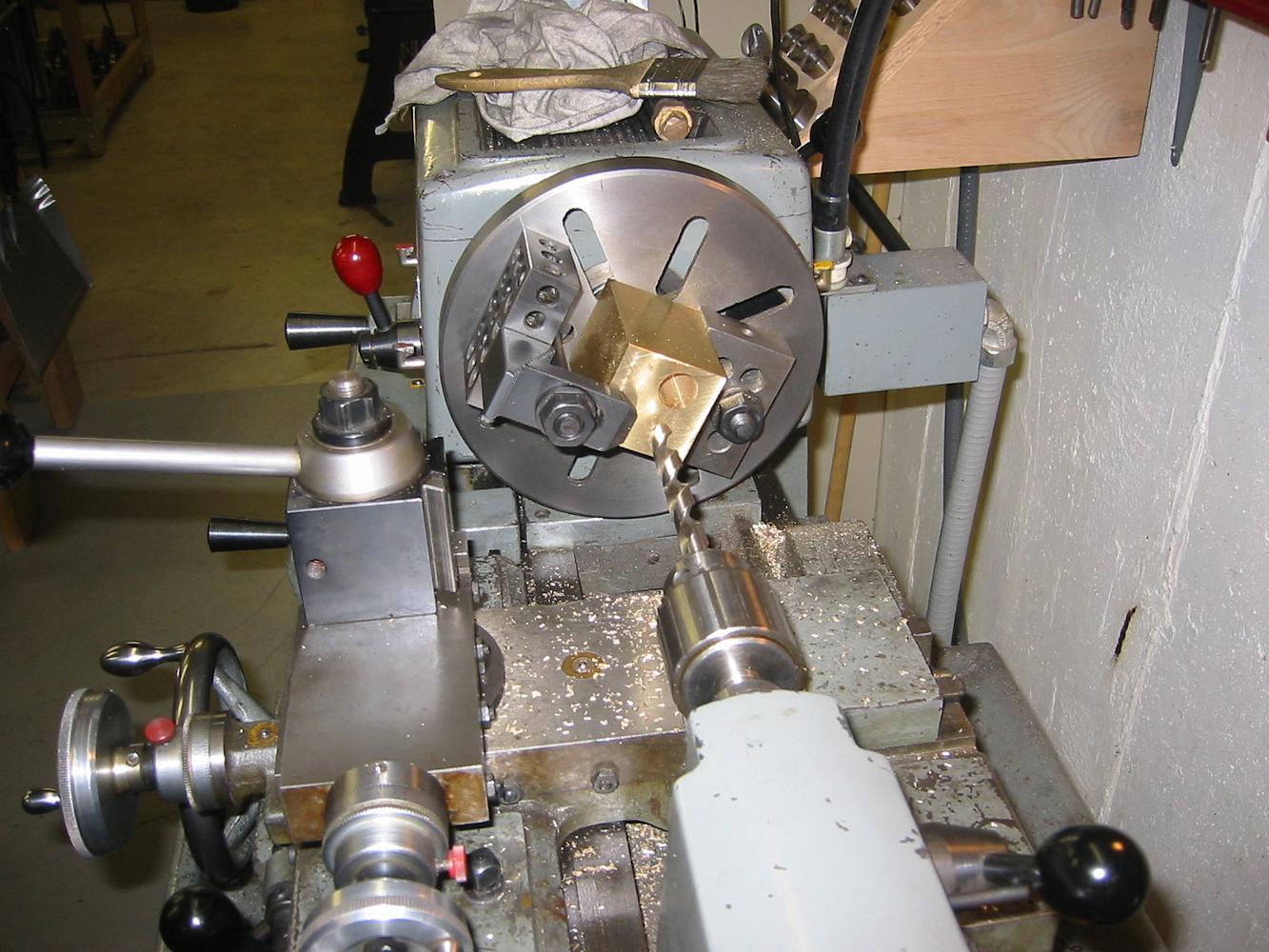
After spending two nights pondering the misalignment of the frames/cylinders/motion structure support brackets, without much success, we set that aside and…
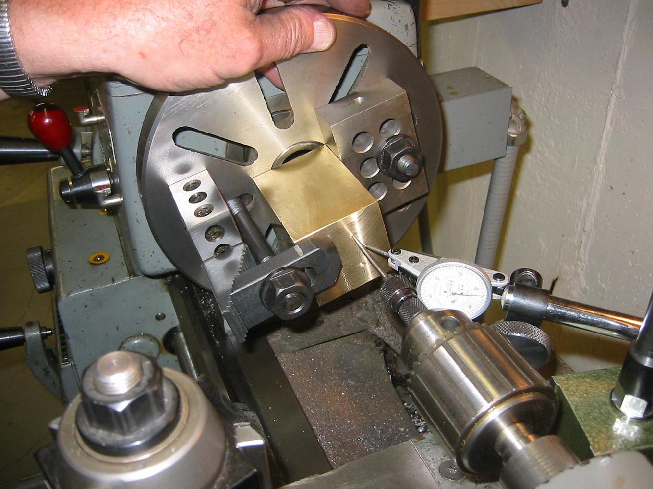
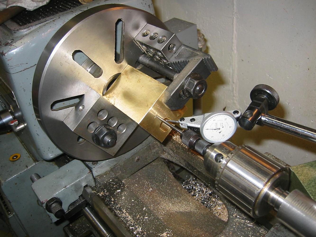
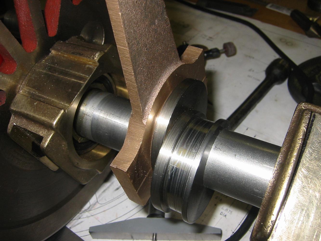
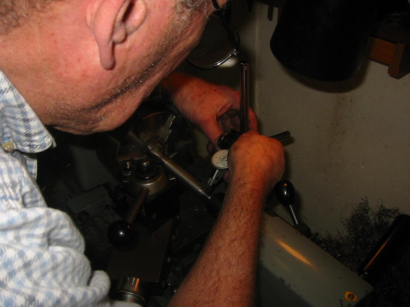
To insure a straight bore, we leveled the lathe all around using the master precision level. After a half-hour of tightening, loosening and adjusting each of…
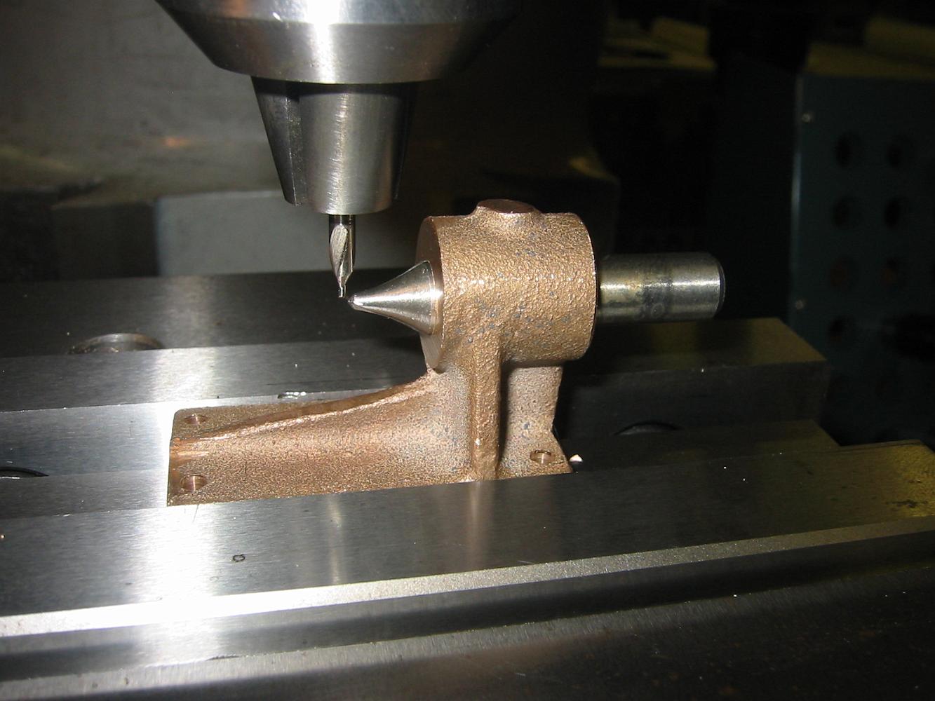
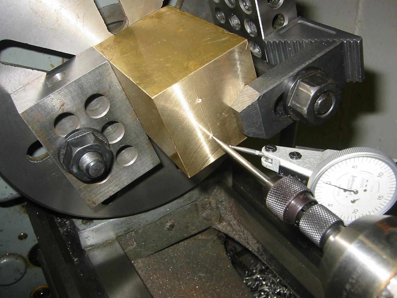
Using the wiggler with the point in the punch mark for the piston center, we put an indicator on the wiggler shaft and move the part around on the faceplate…
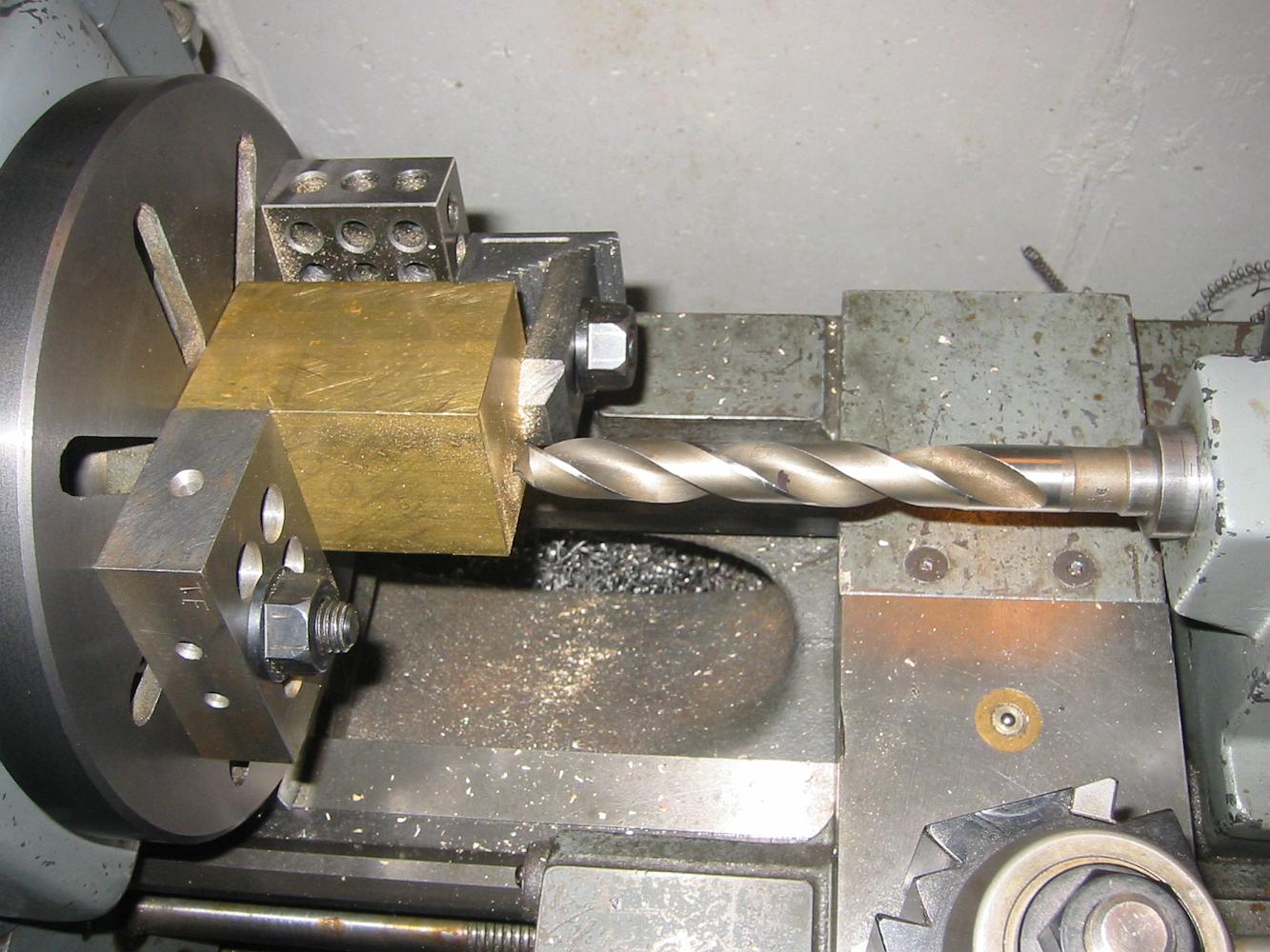
With the first hole completed we start on the second one. Measuring the first completed hole, we find .0004" taper in it. Well within the tolerances called for…
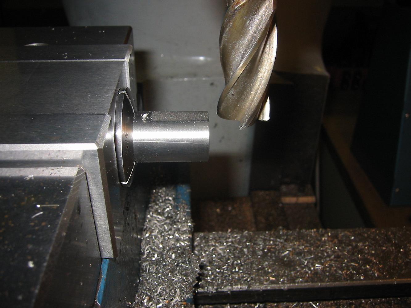
One of the challenges of boring a 2-3/4" deep by 3/4" diameter hole is getting a small but long enough boring bar. Which I don't have. So we use three…
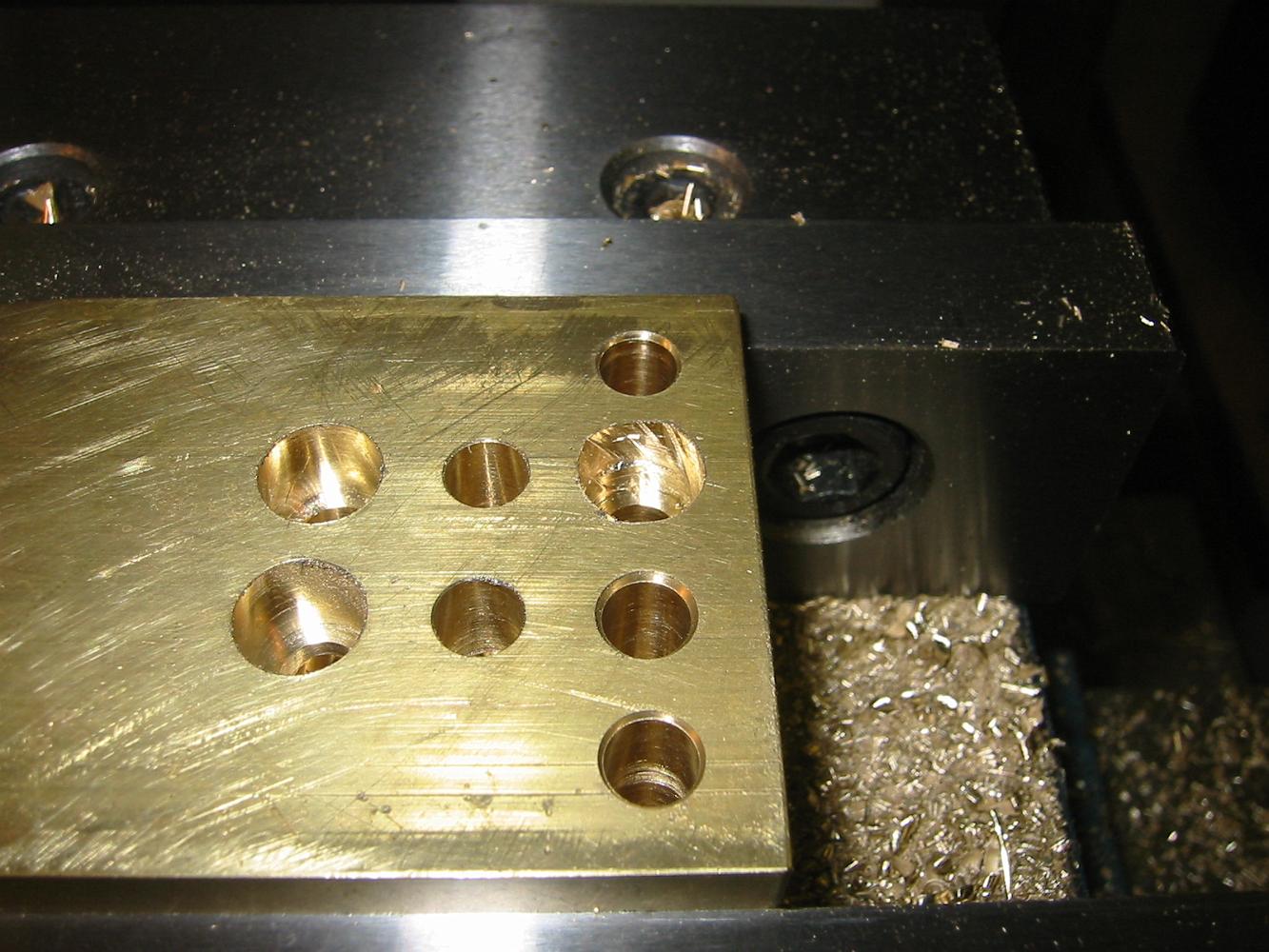
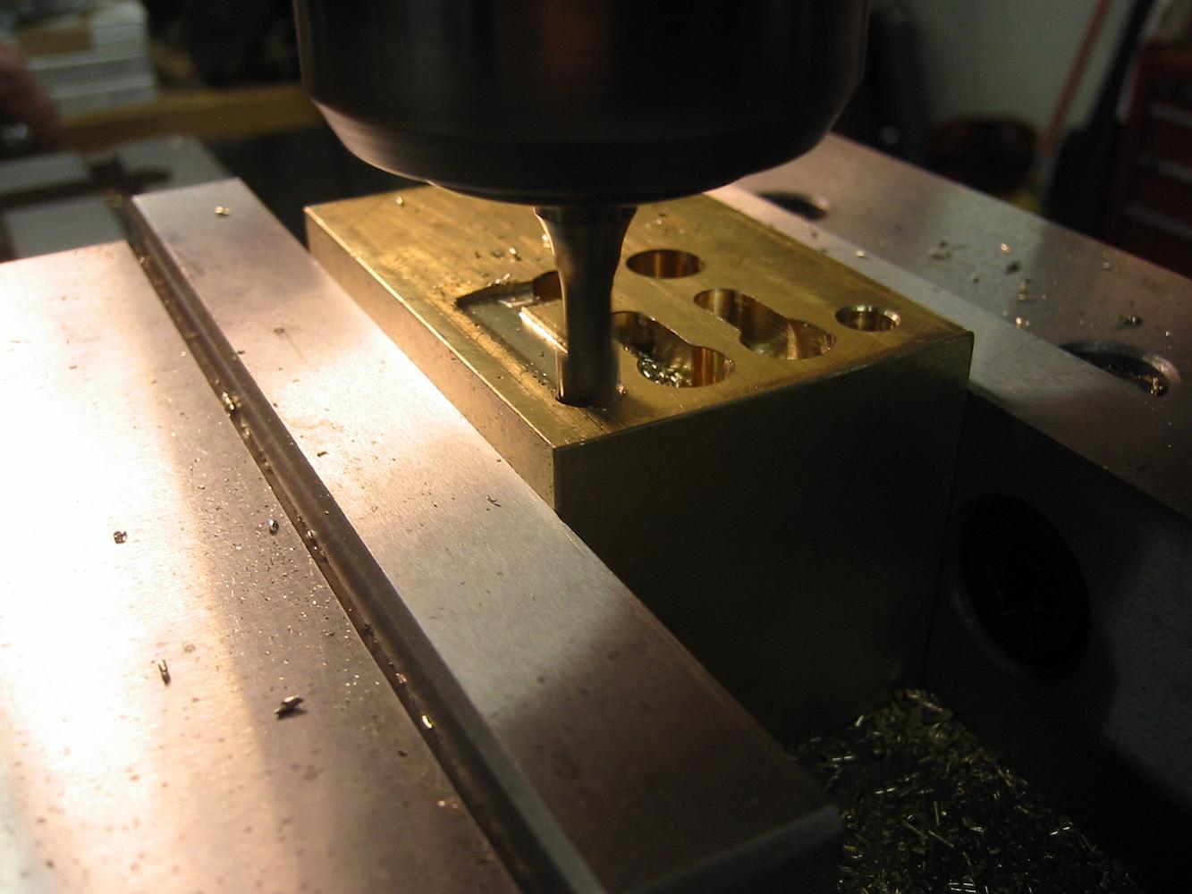
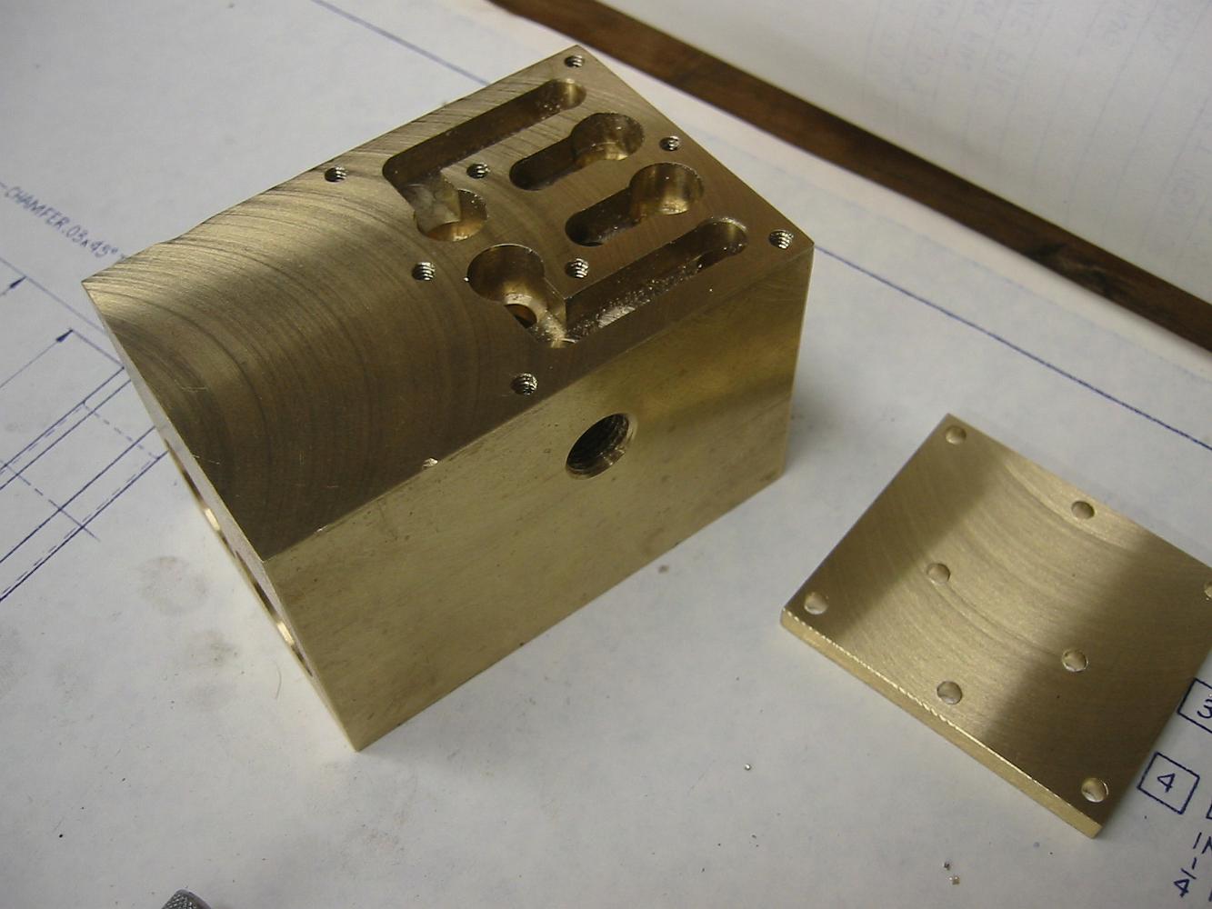
A crash while drilling the water holes. All the holes look good except for the second on the top right, where the cutter dug into the brass and broke two…
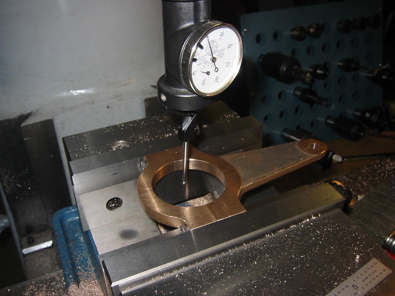
15-Dec-07 Another Saturday work day. After drilling the hole for the piston ram, the eccentric strap is centered with the coaxial indicator for a finish bore.
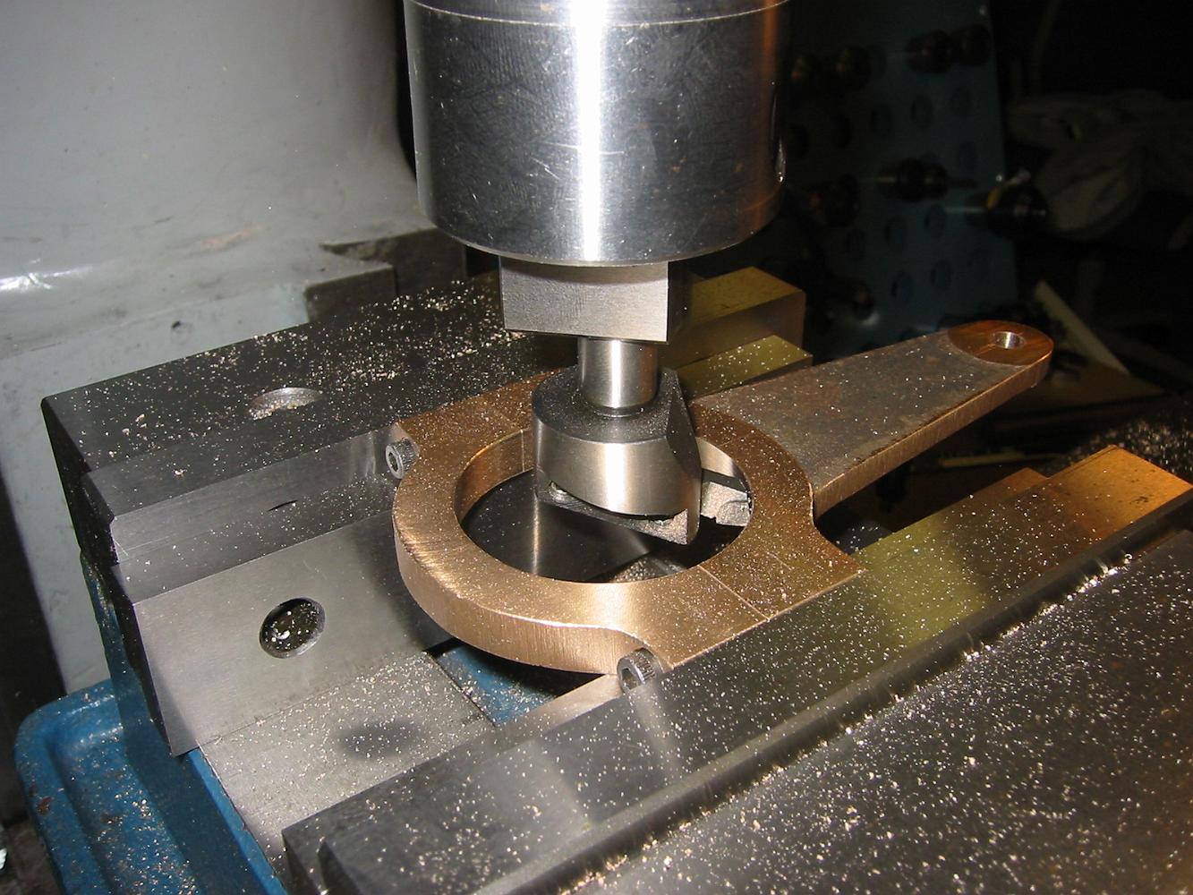
To bore the 2" diameter hole, a fly cutter is held by the boring head instead of the usual boring bar. Once we drill the zerk fitting for lubrication in the…
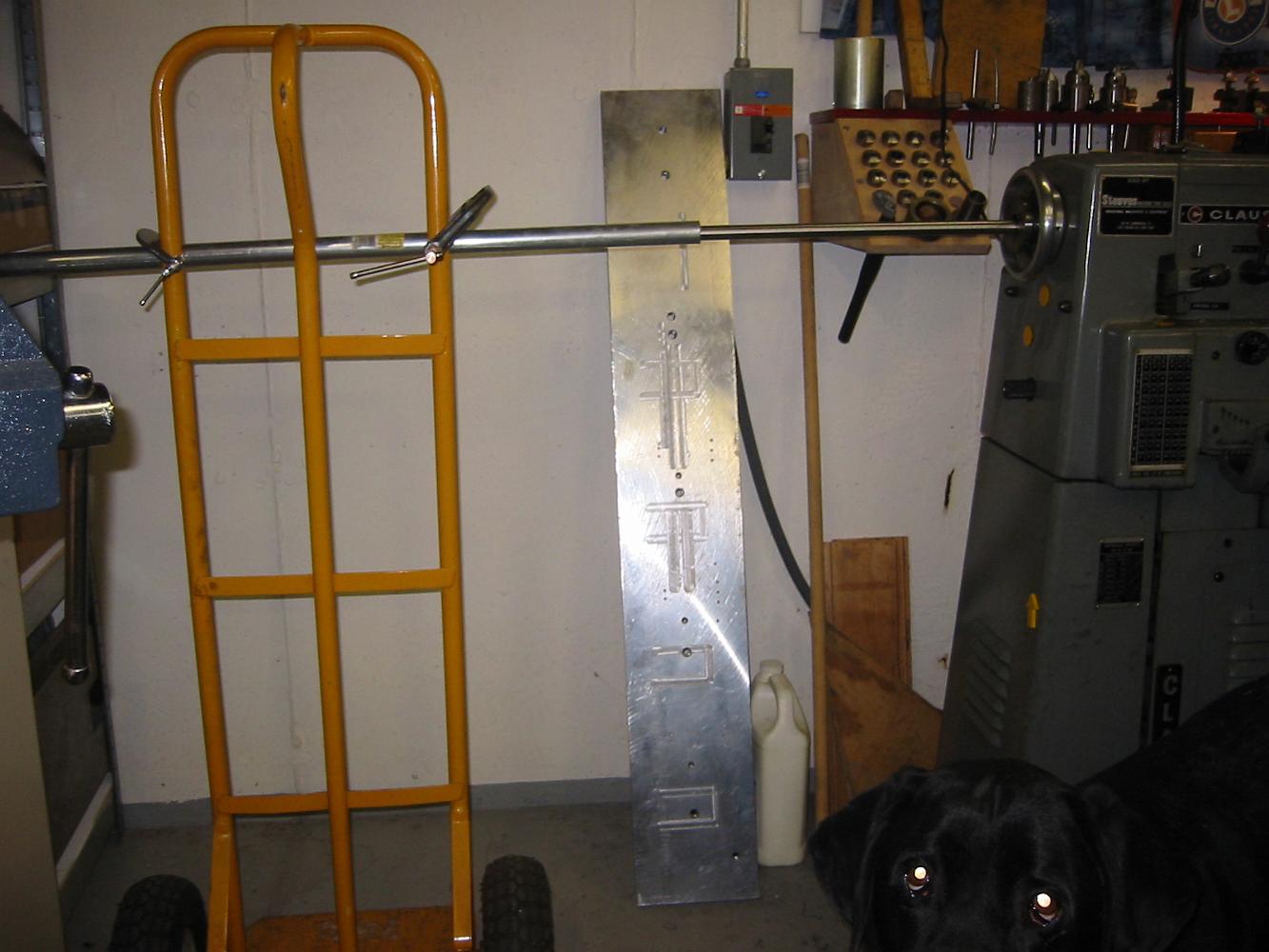
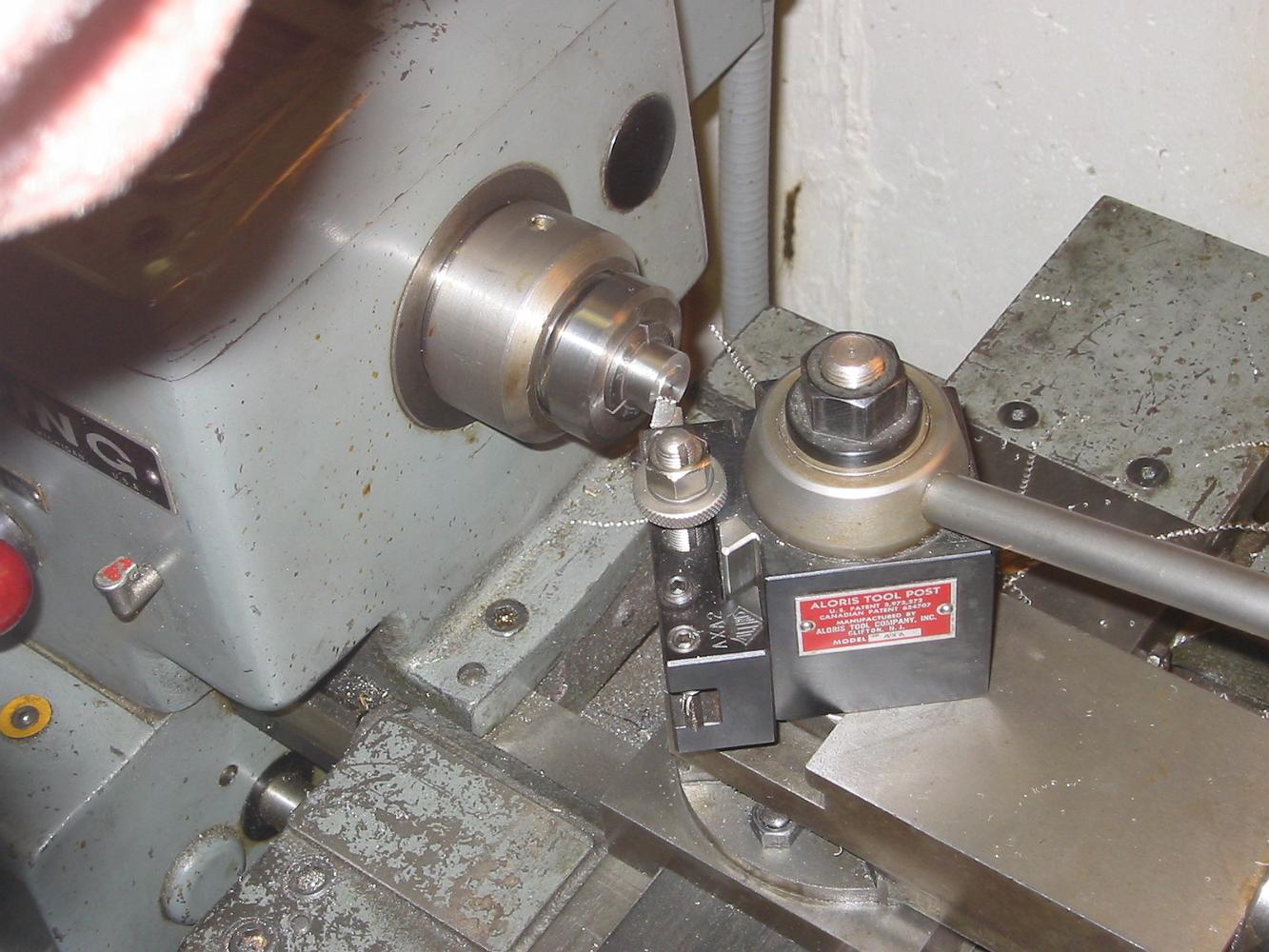
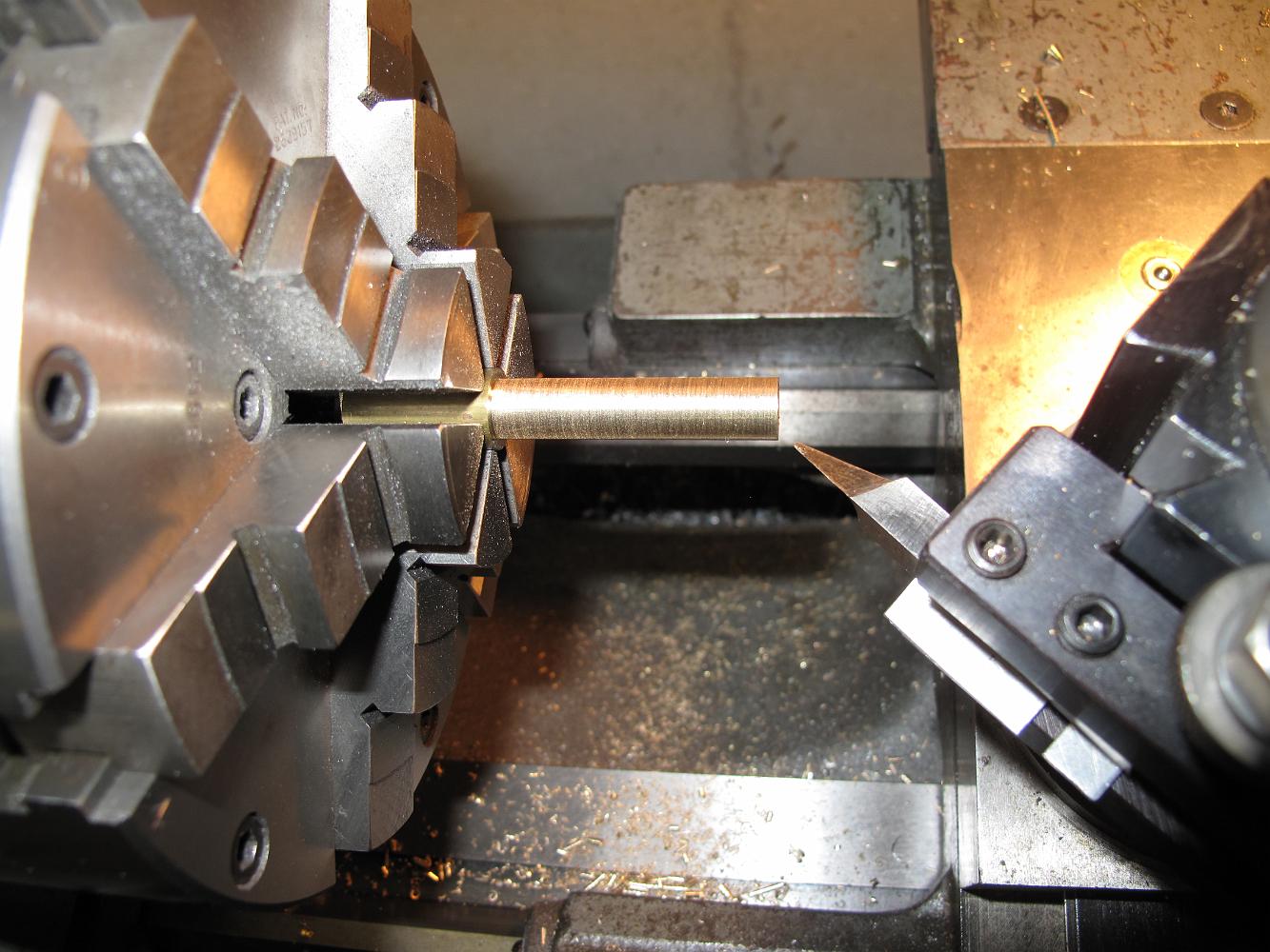
3-Jan-08 A makeshift stock holder for the lathe. This kept the end of the 1/2" stainless steel shaft from whipping around and bending while we hold the rest in…
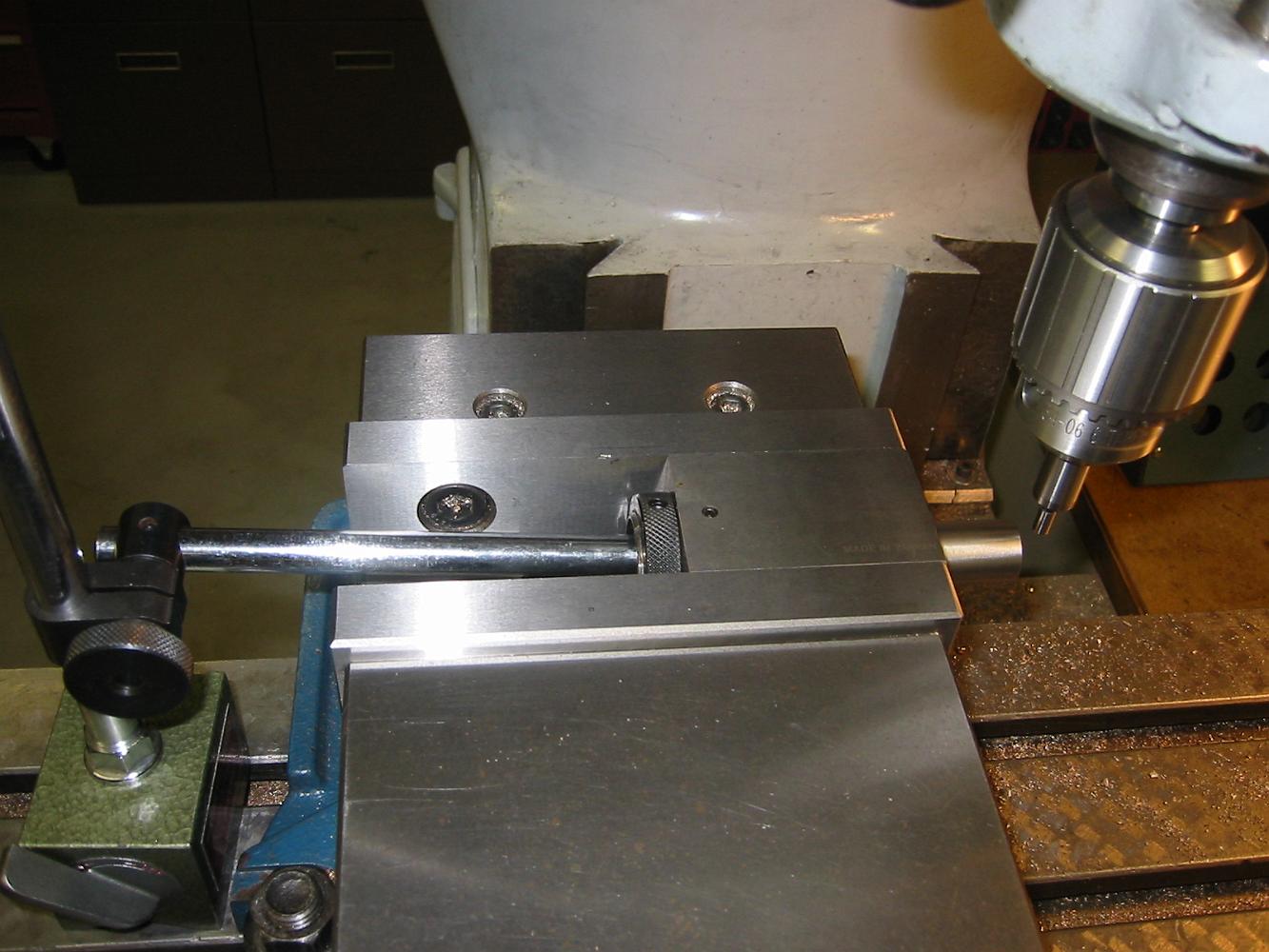
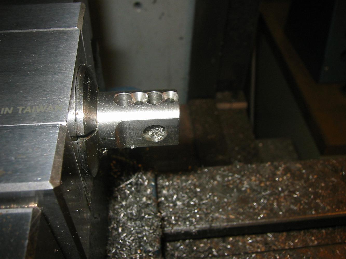
3-Jan-08 The set up to slot the pump ram and drill the clevis pin. We are using a 5C square collet holder, the magnetic base as a stop. This will allow us to…
Unlike the first piston, we end mill the flat instead of side milling, which make things much faster.