30-July-08 Putting the squeeze on the Expansion Link. My friend Tim M. who is also making a Heavy Mike had his expansion links cut from Stainless Steel by a…
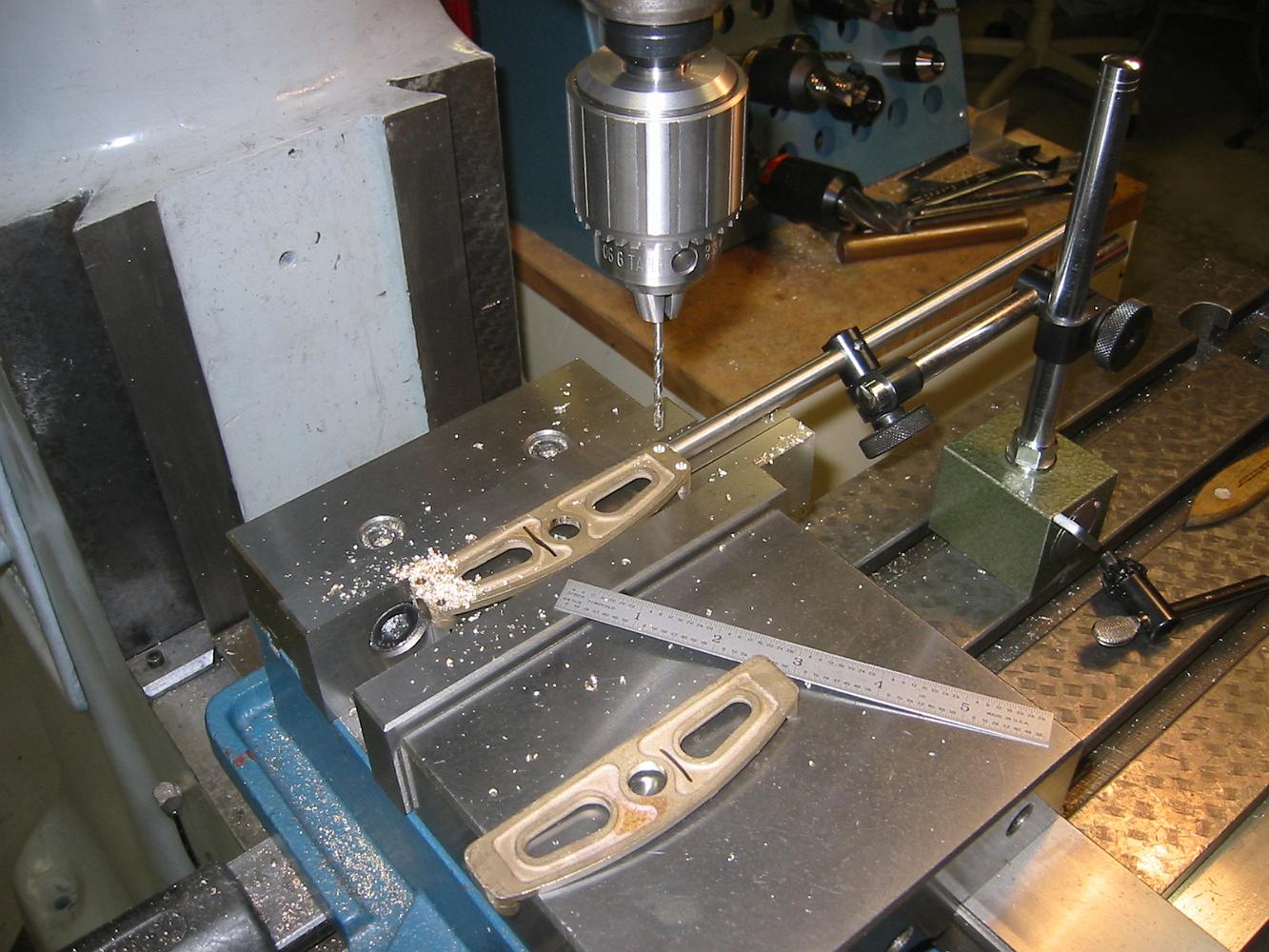
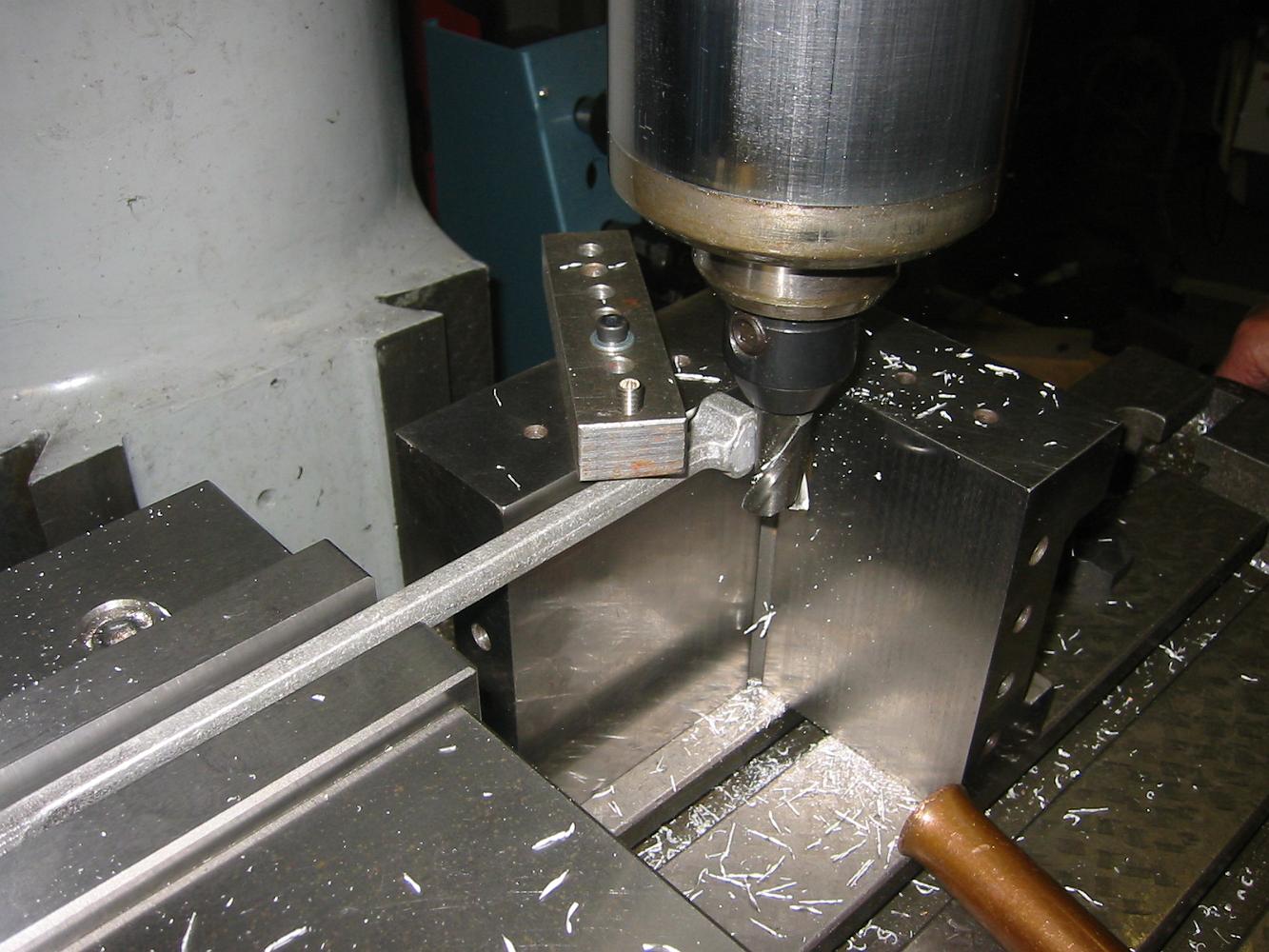
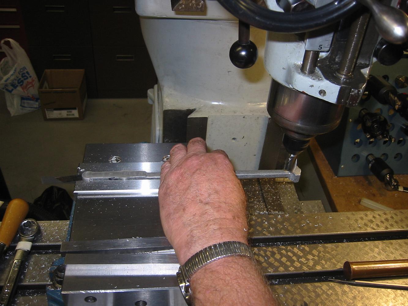
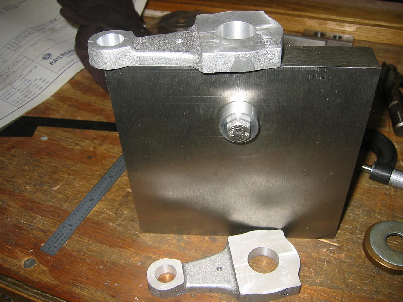
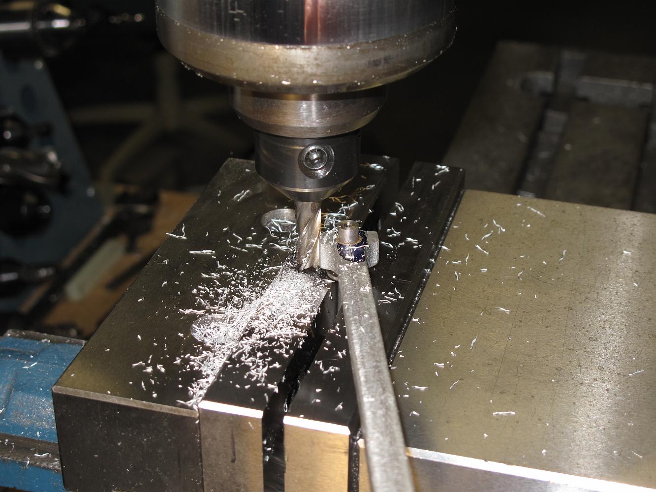
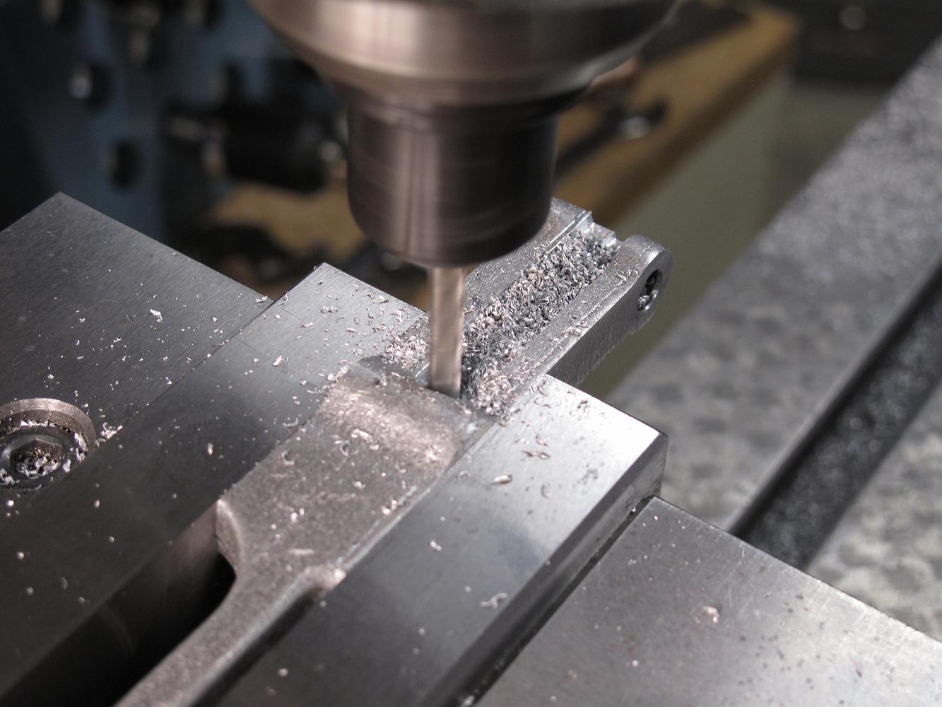
Without changing the setup or the most importantly the center zero, we move out and drill the four bolt holes, but not the two locating dowel pin holes. We'll…
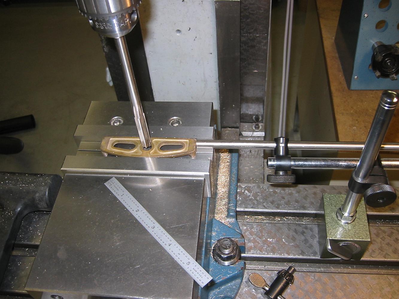
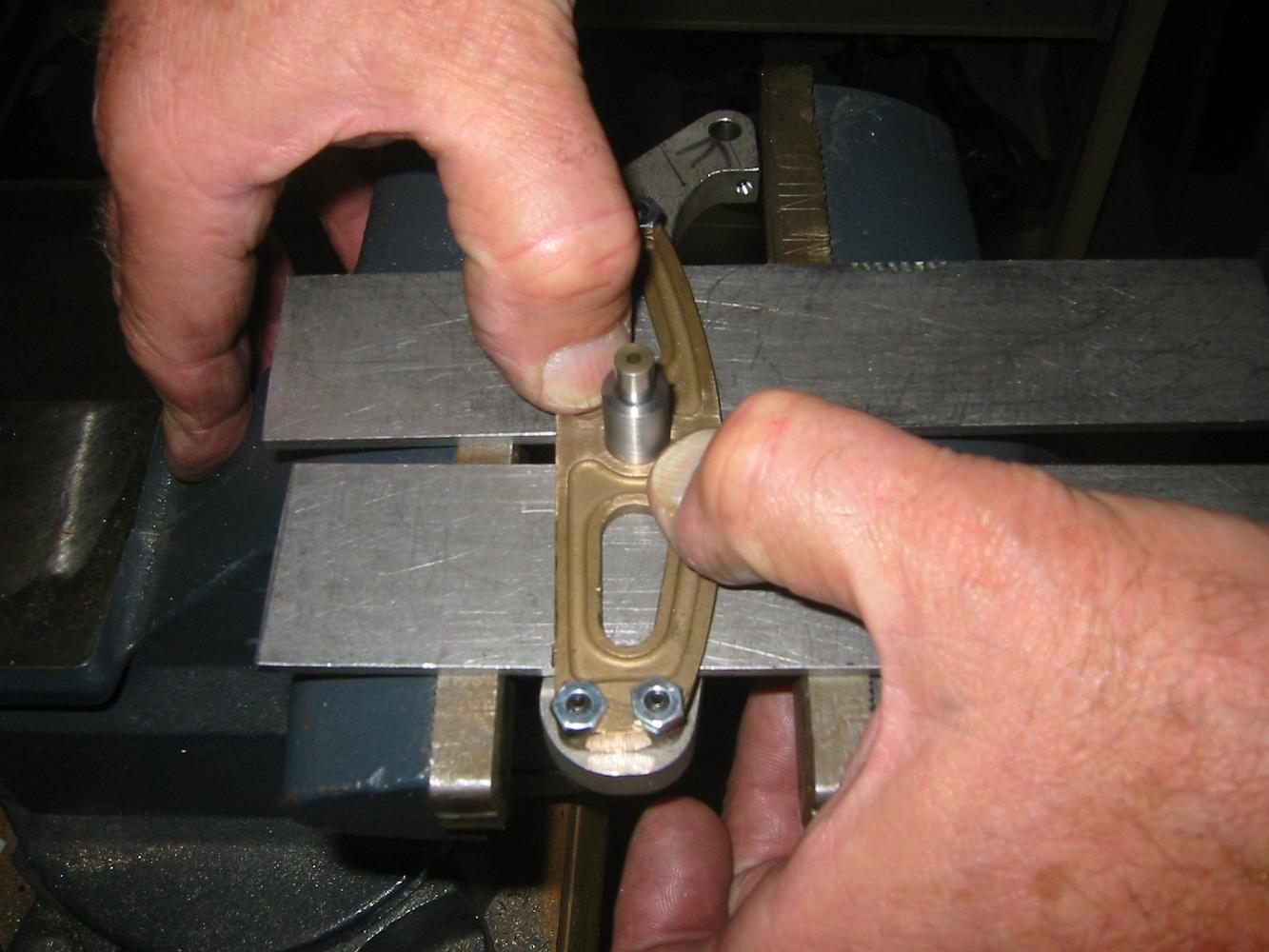
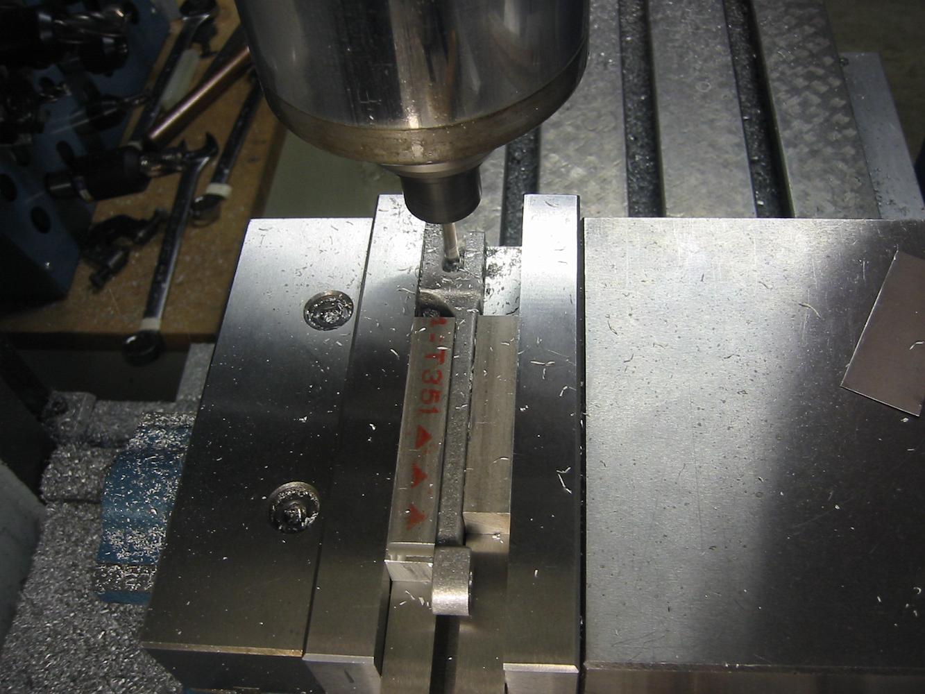
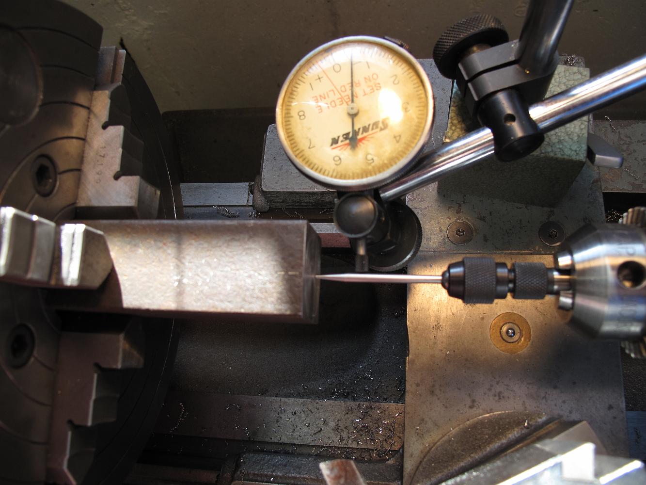
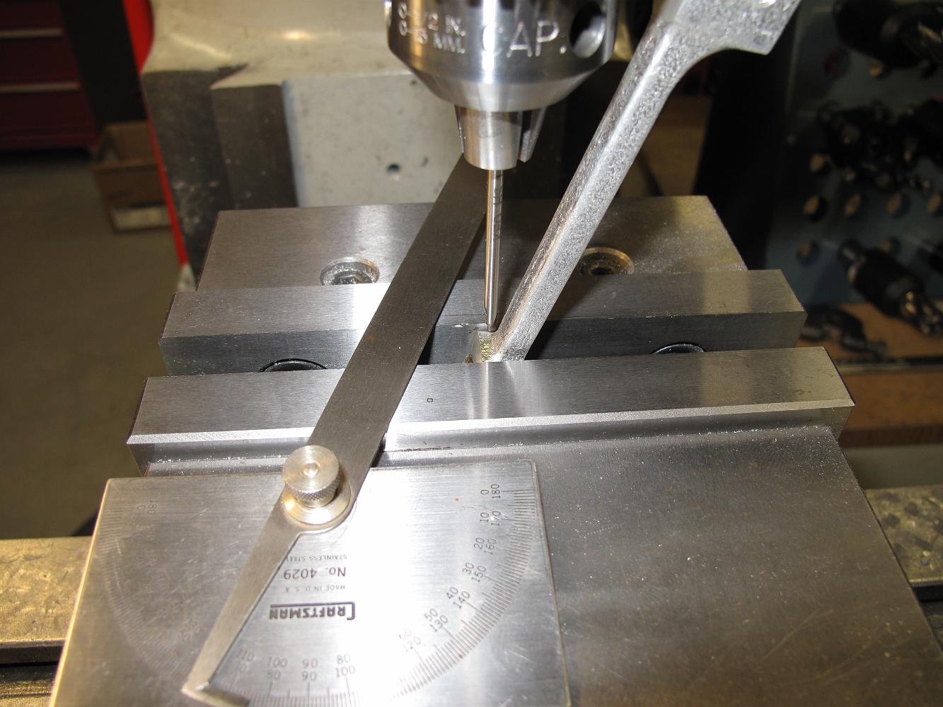
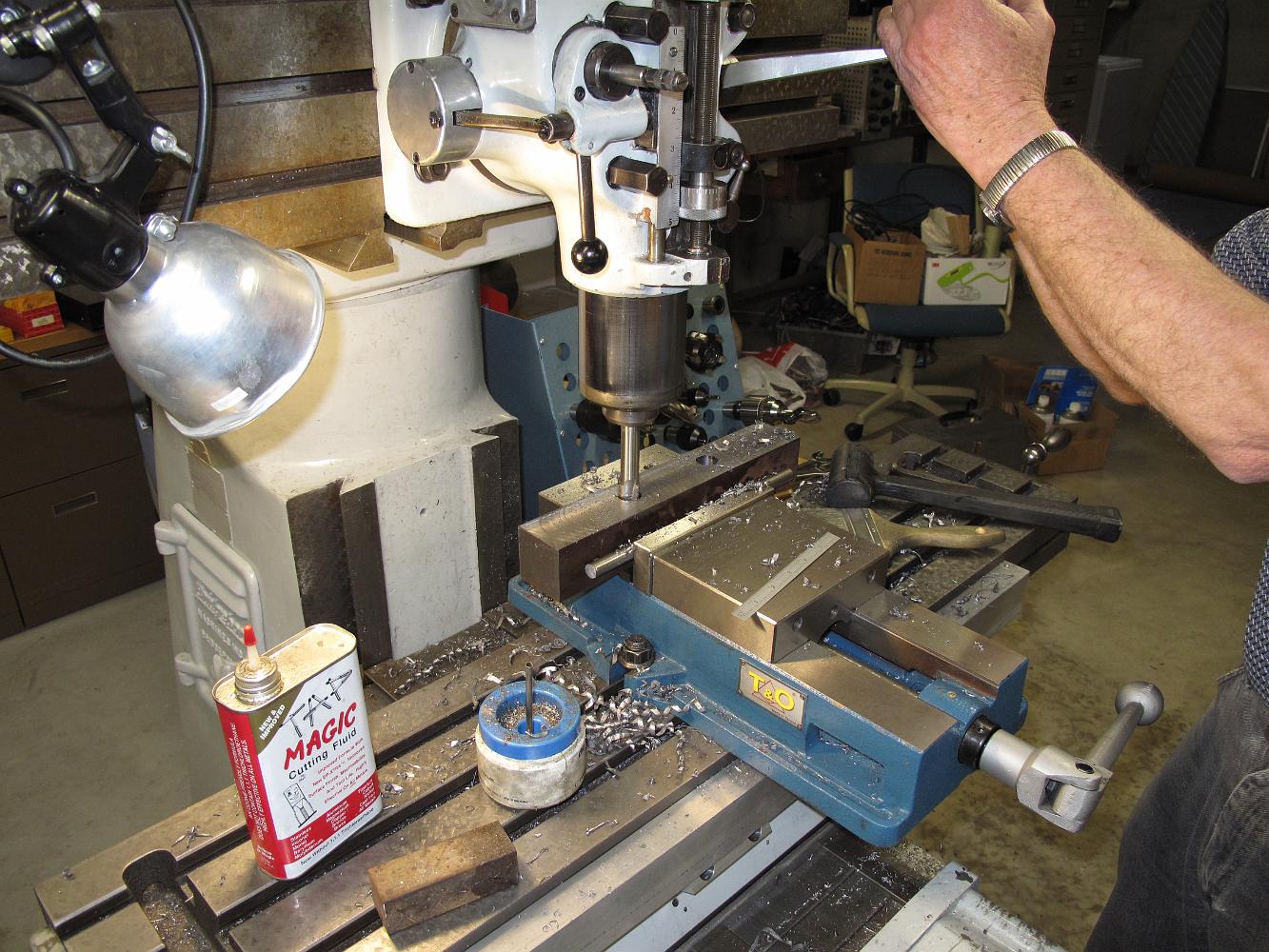
We decided not to follow the assembly instructions provided and do our own thing. Setting up a stop in the vise for all the parts, we center the reamer and zero…
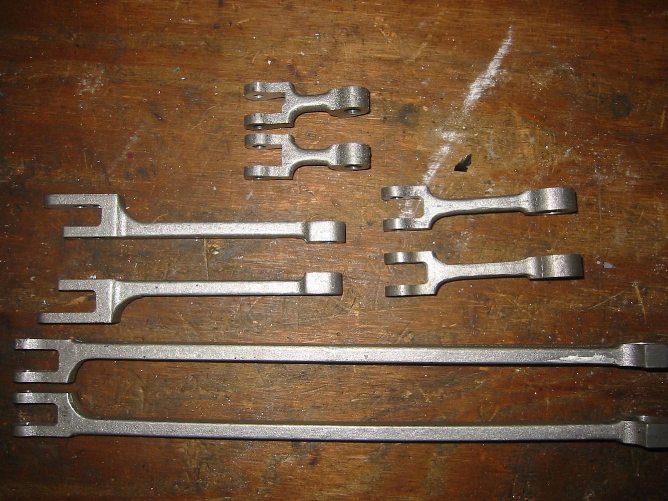
23-July-08 We start a new section! Yeah! Starting with the Trunion Link Supports, we trim the sprue end off and machine the ends to a uniform height. Like all…
Checking the bored hole with and oversized (.251) dowel pin. The hardened stainless finished up nice and smooth, which is good since this hole is also a bearing…
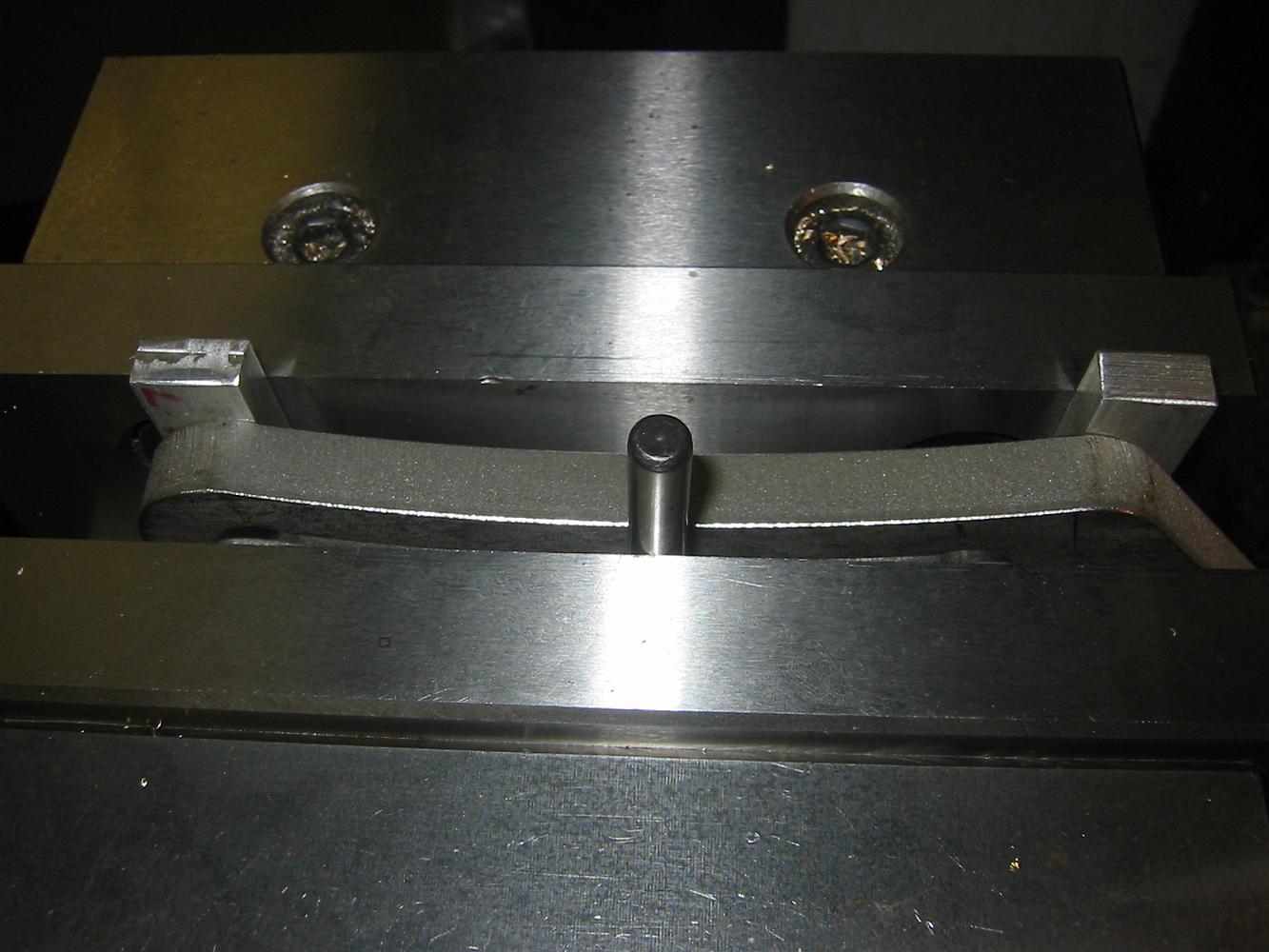
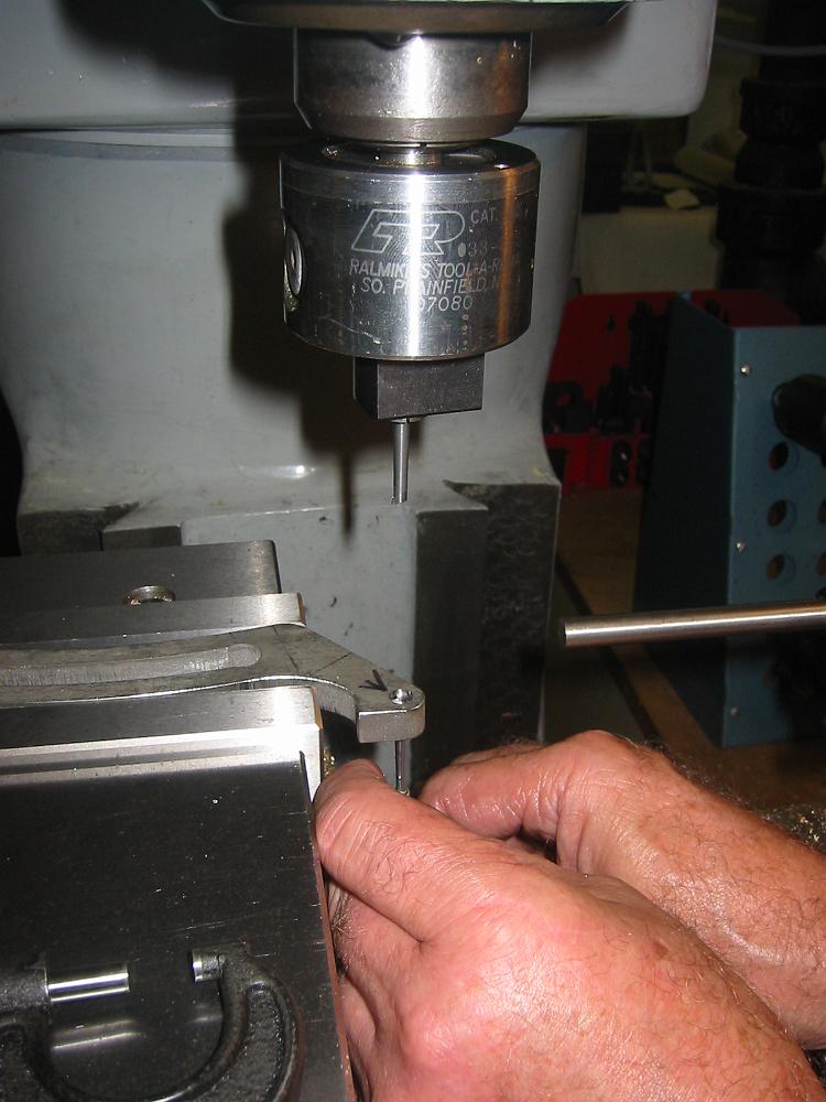
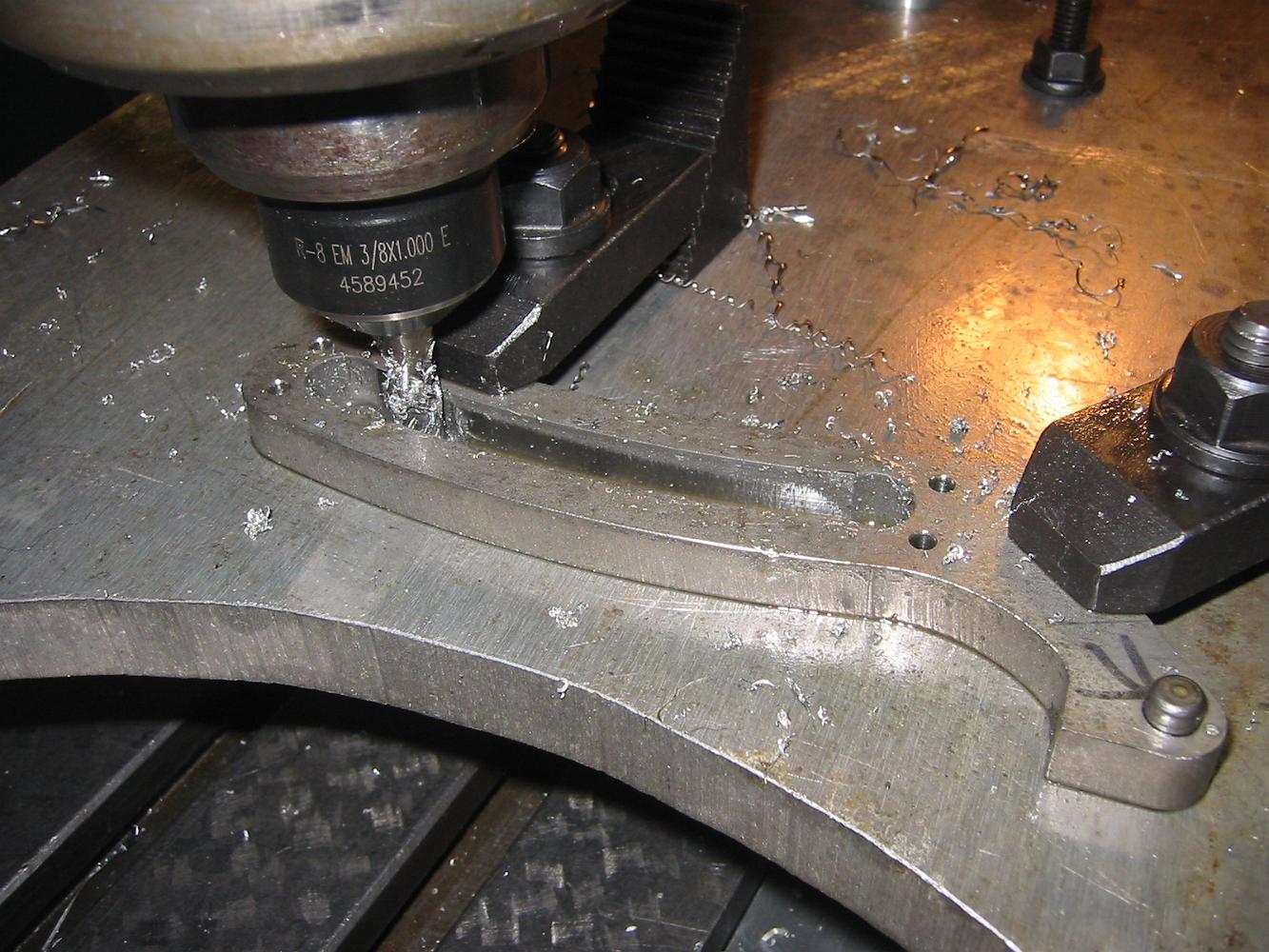
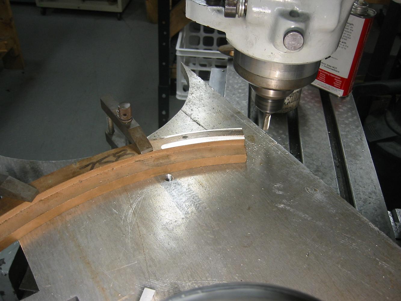
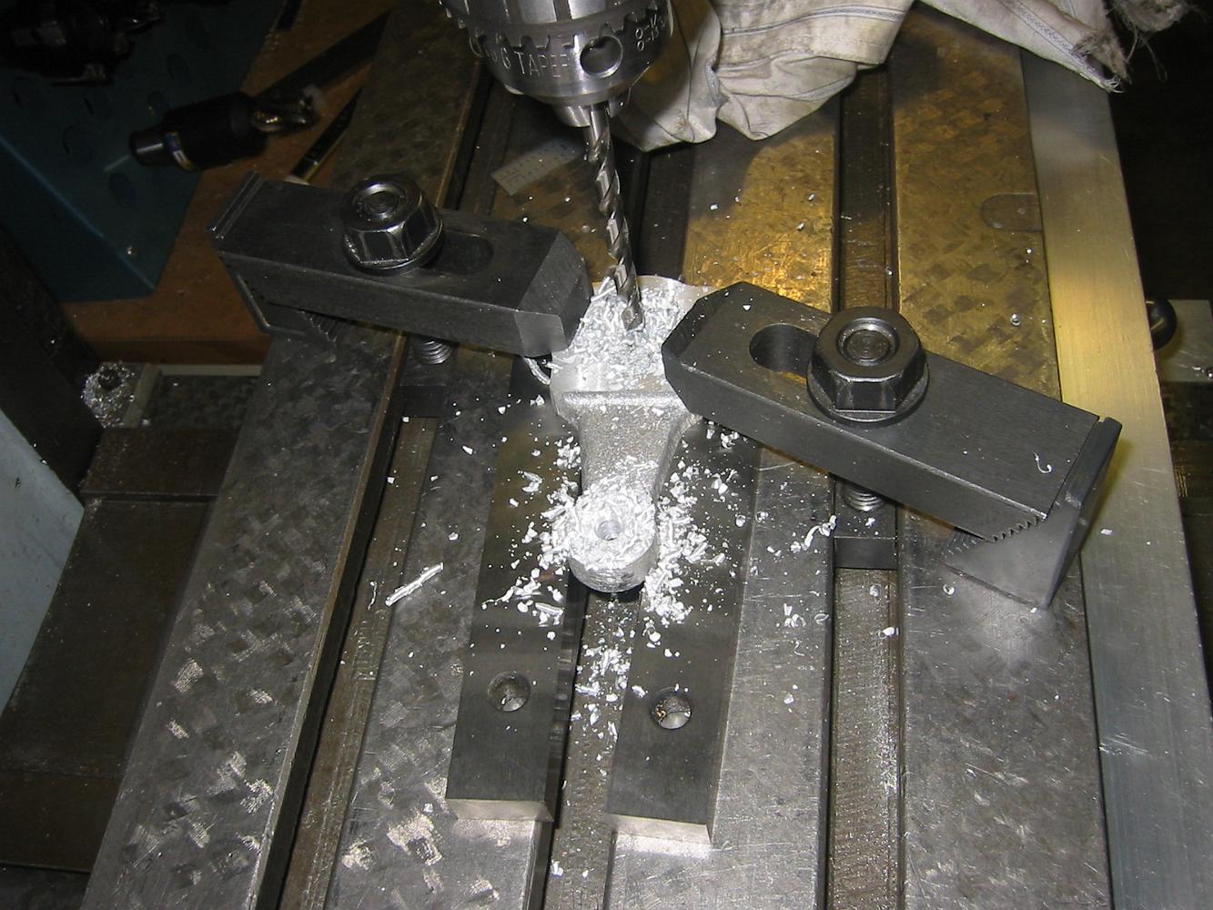
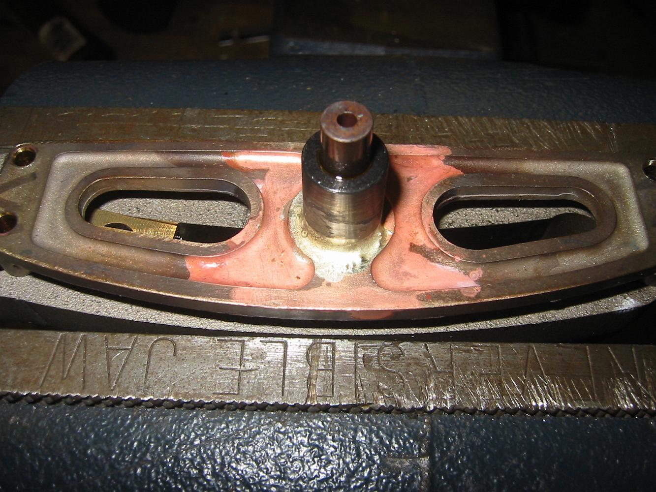
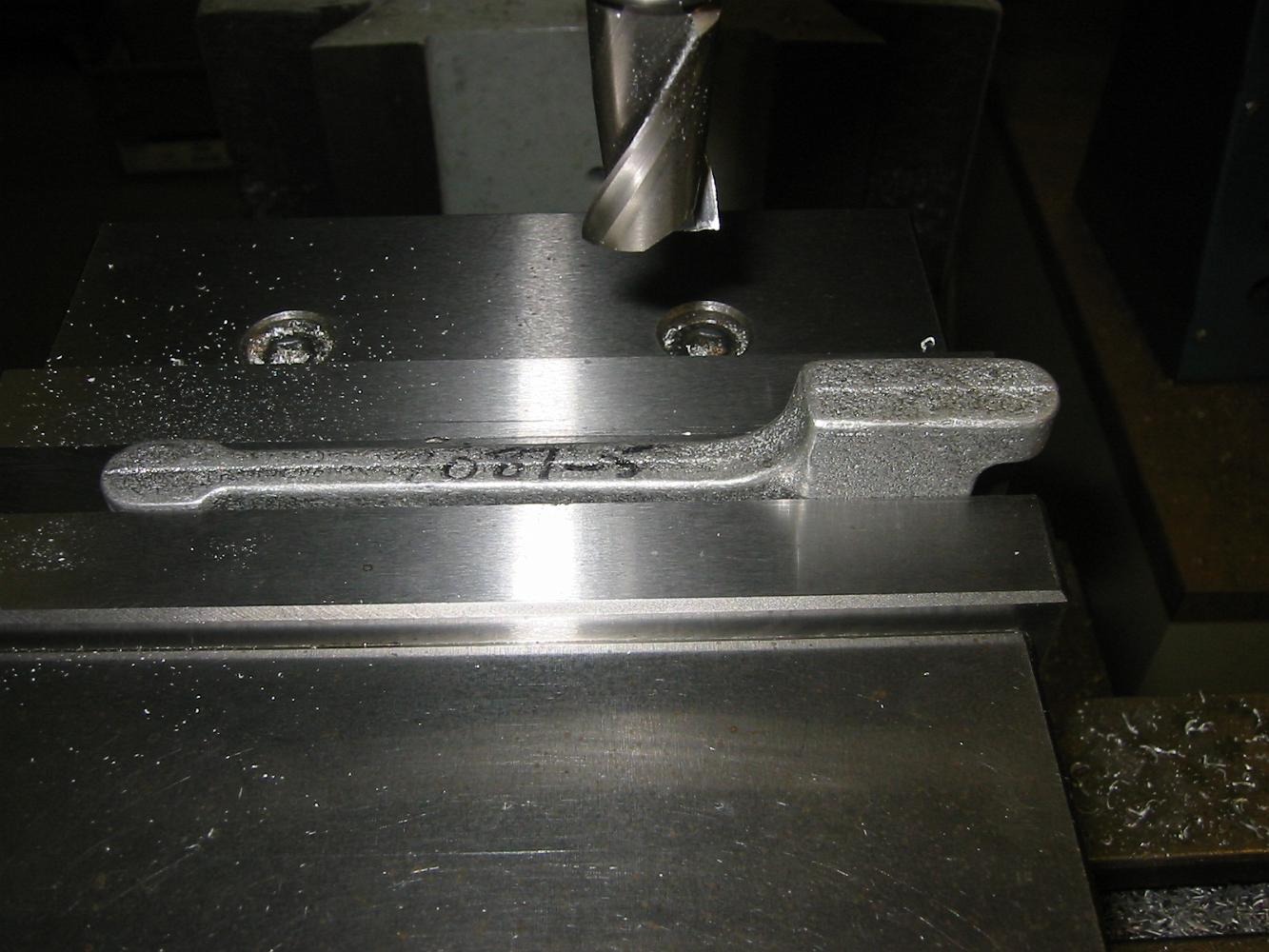
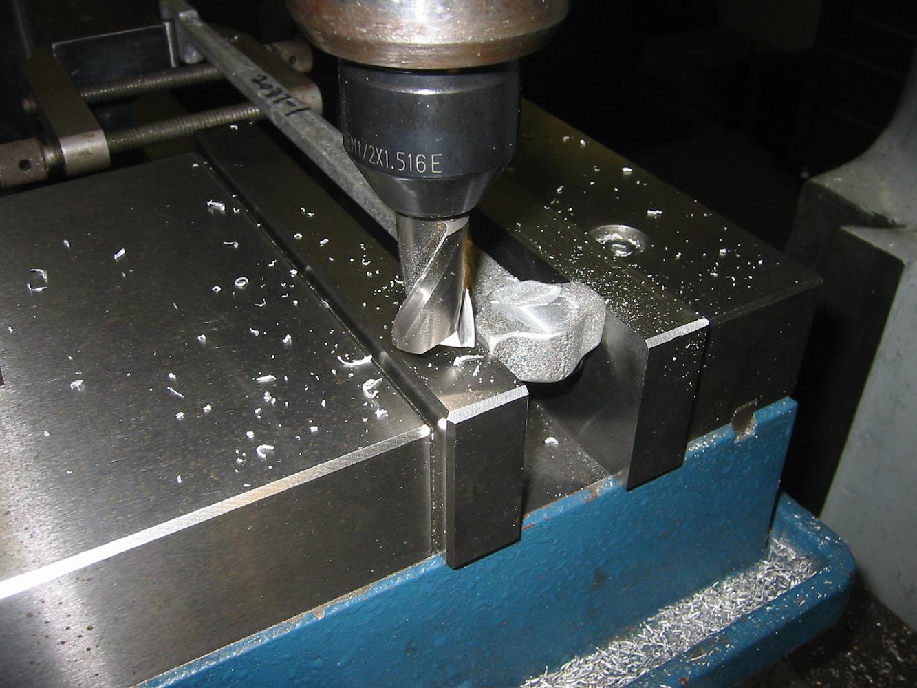
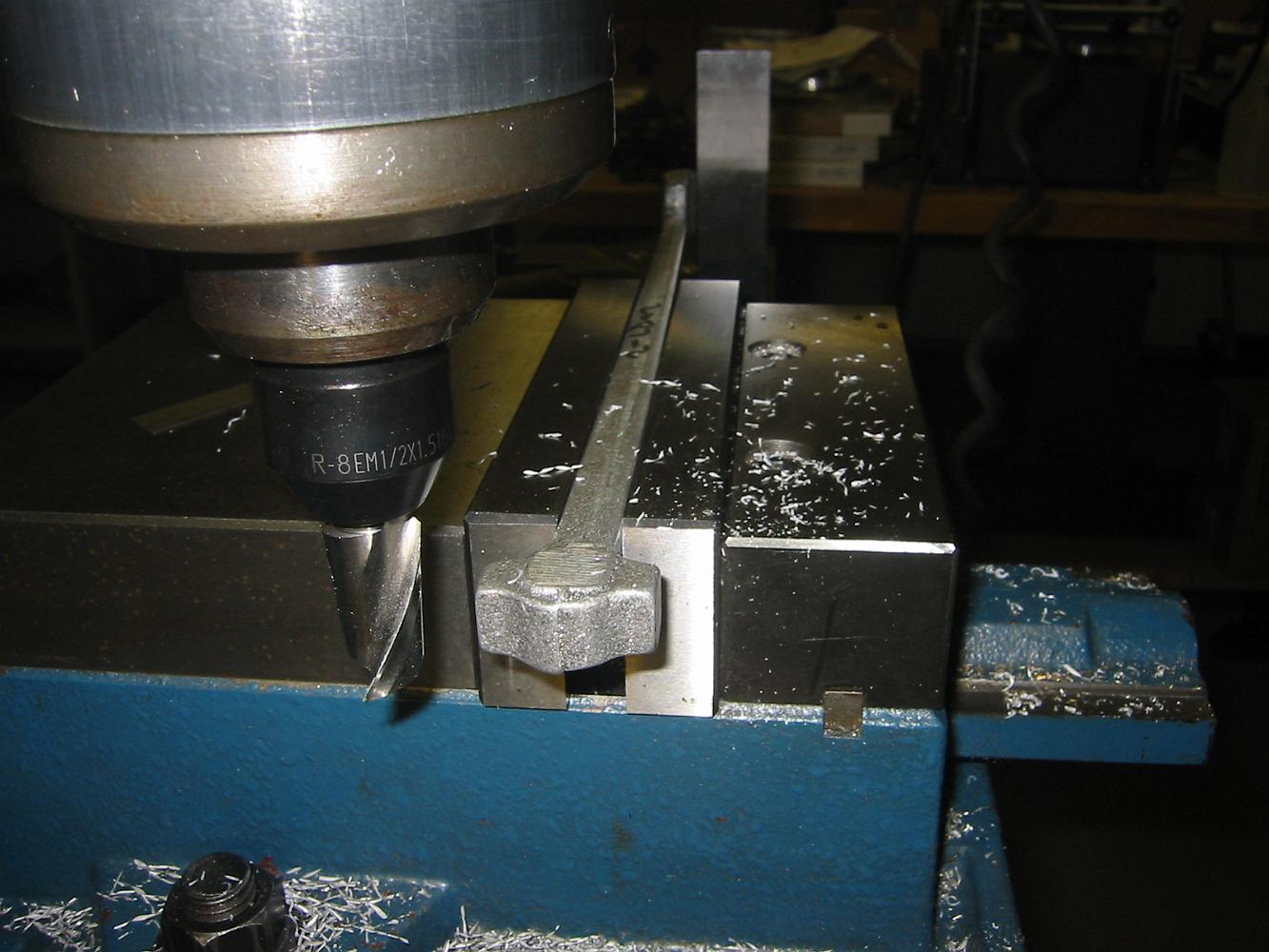
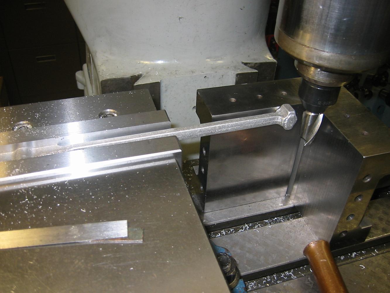
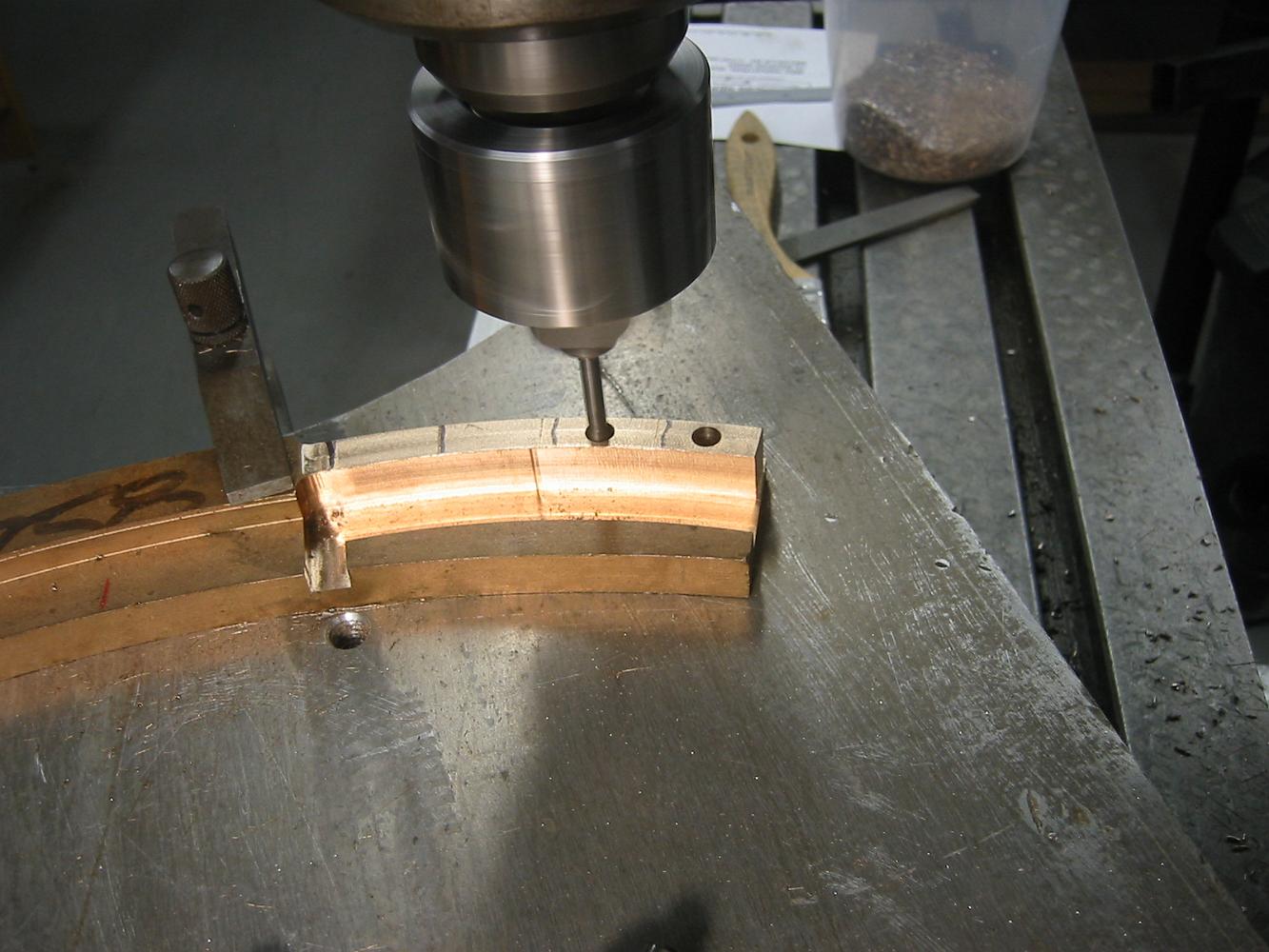
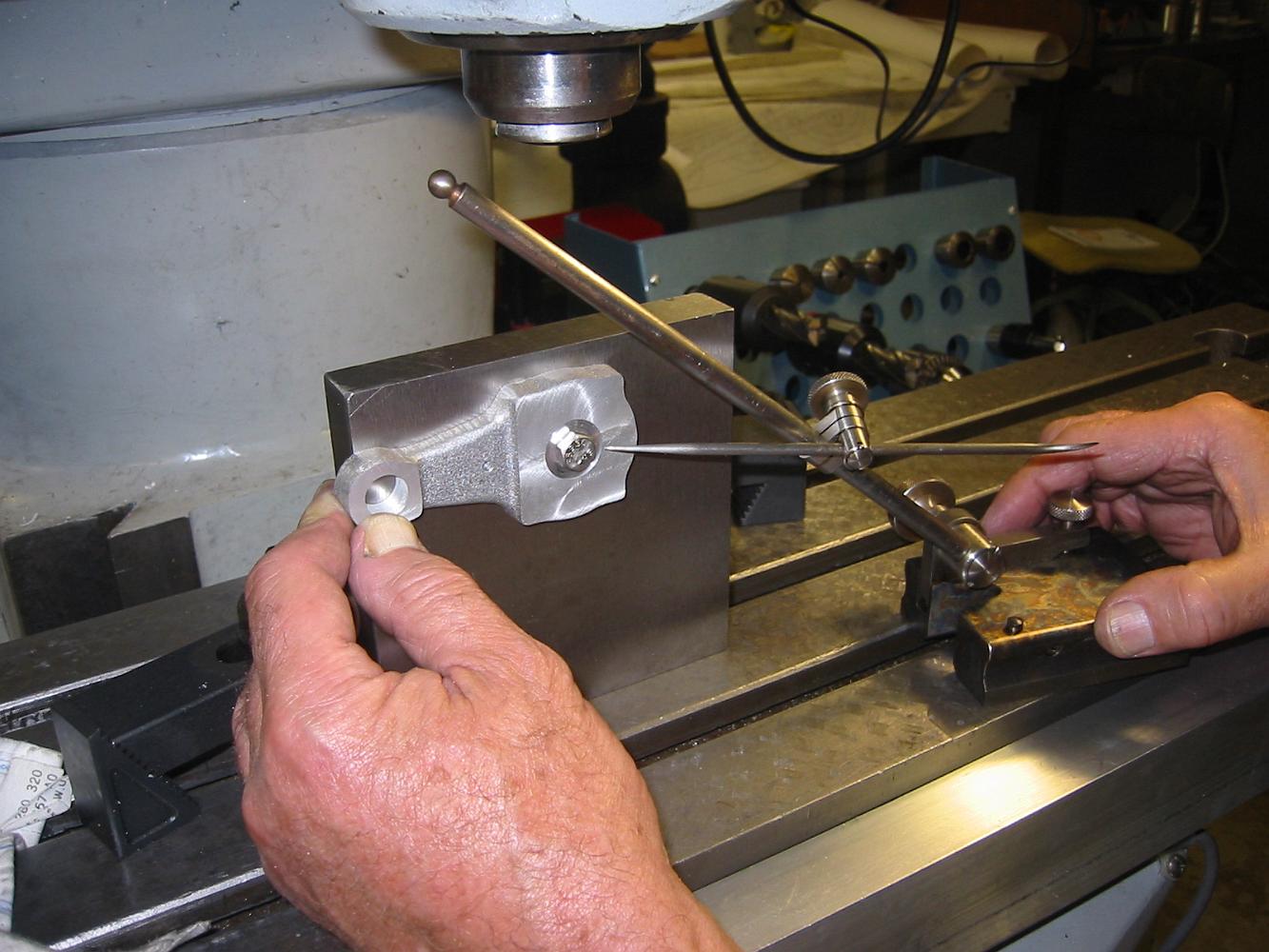
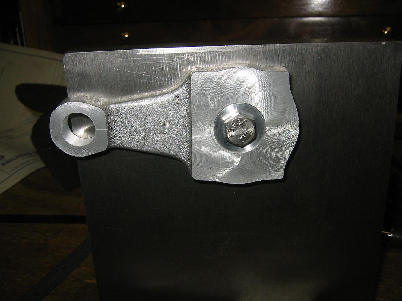
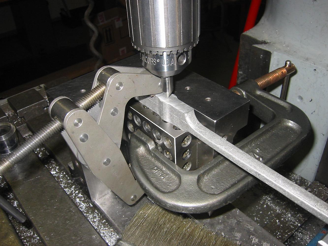
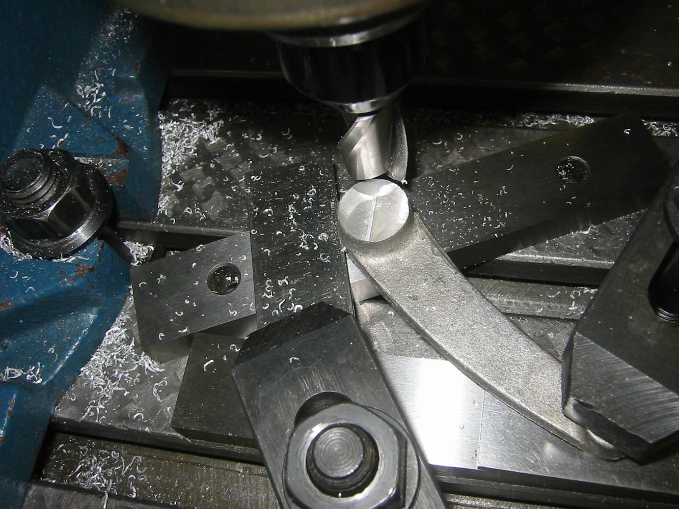
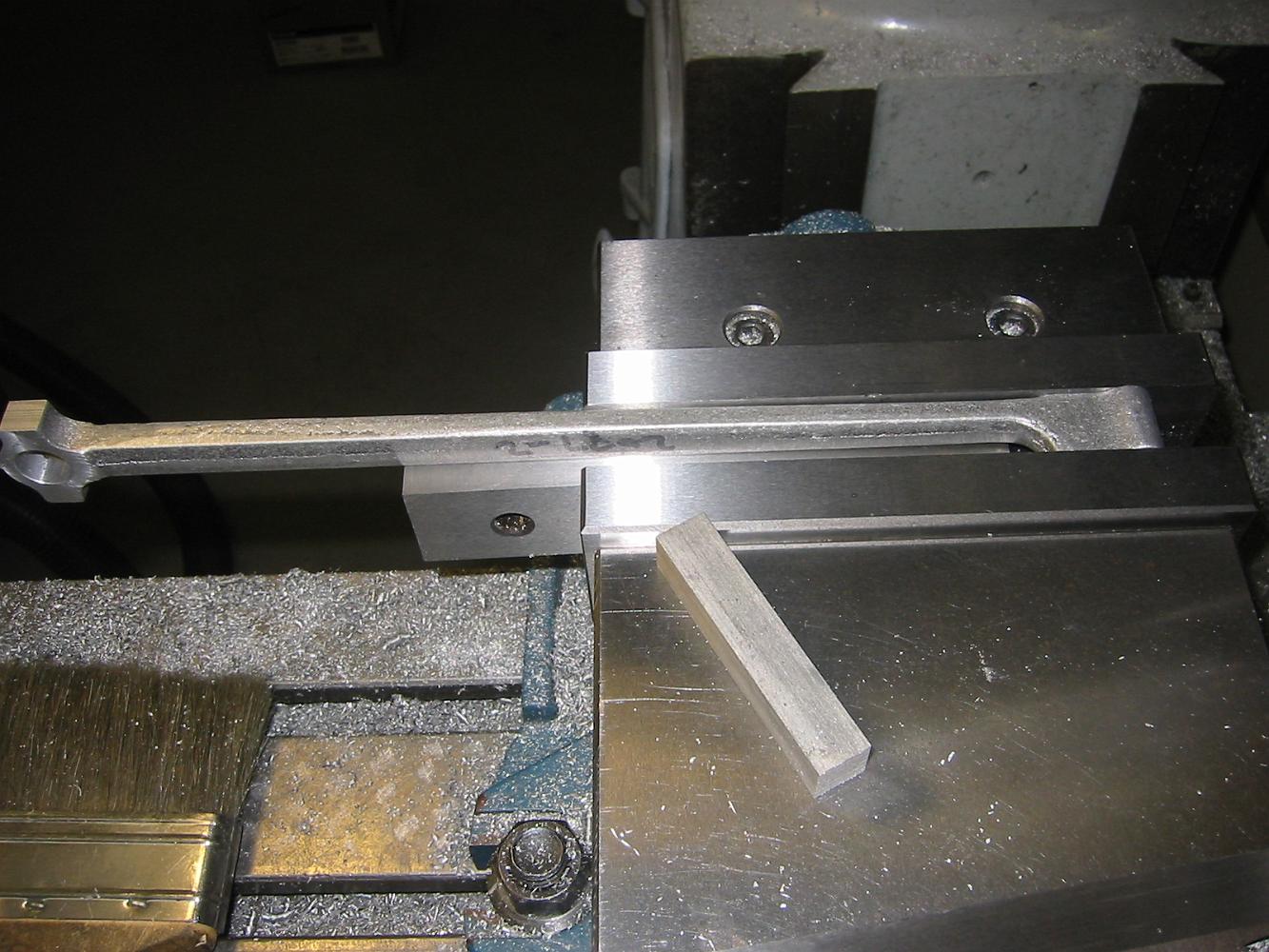
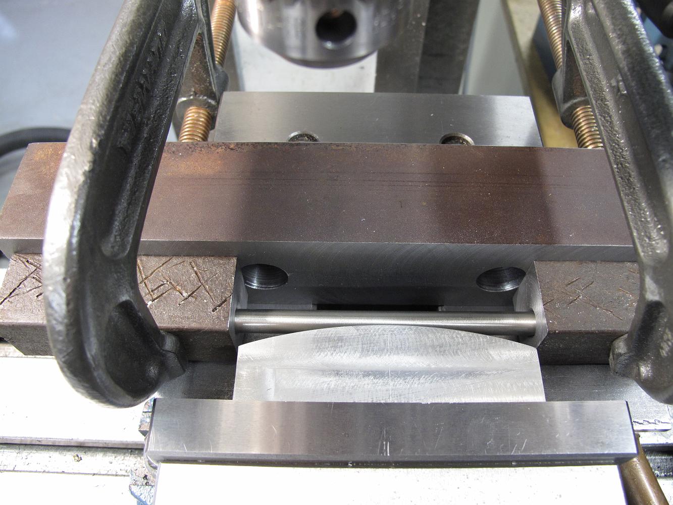
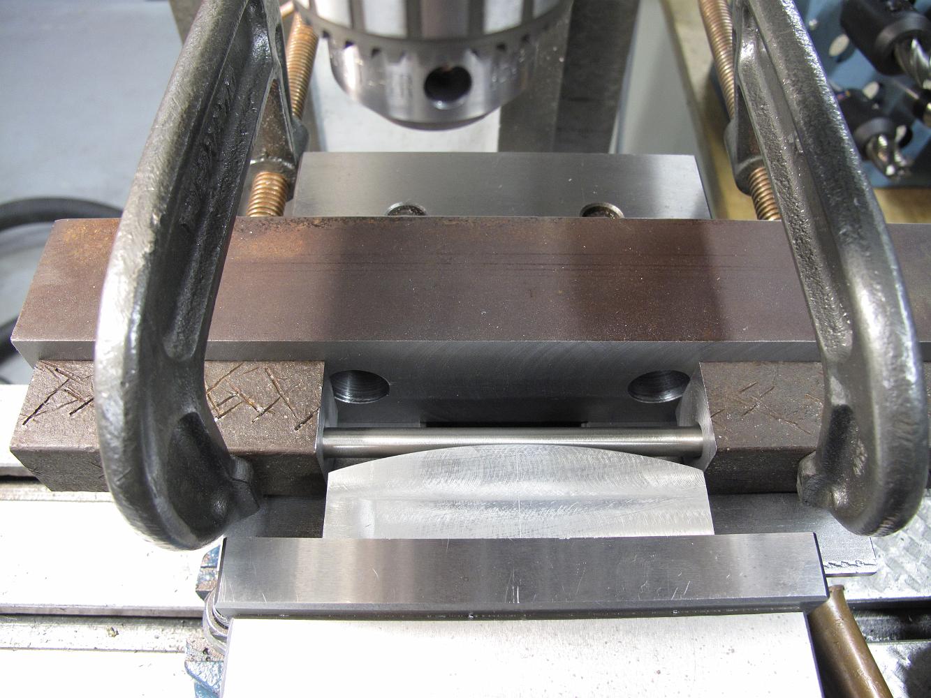
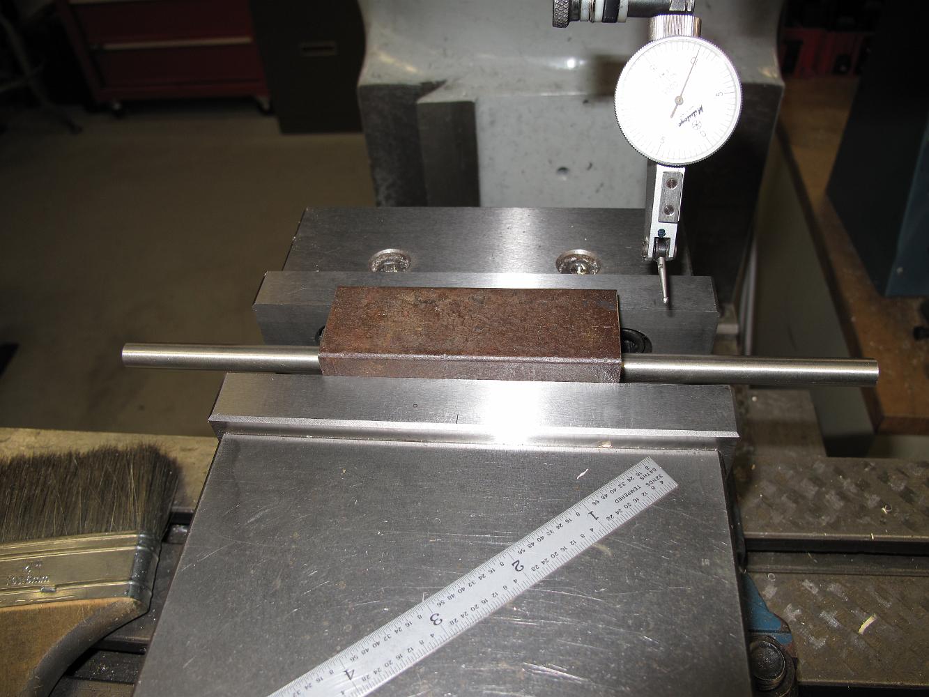
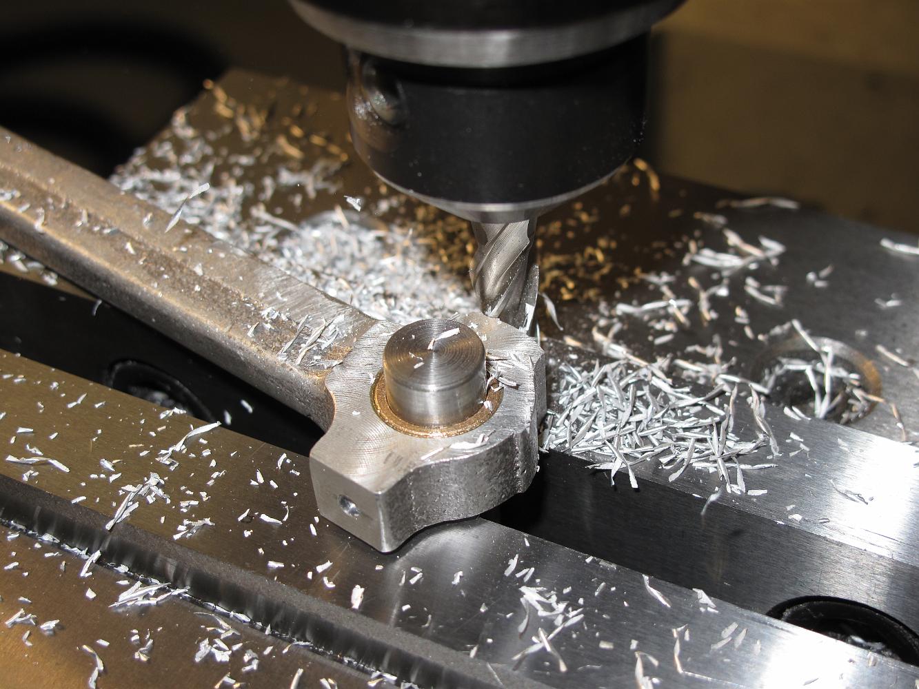
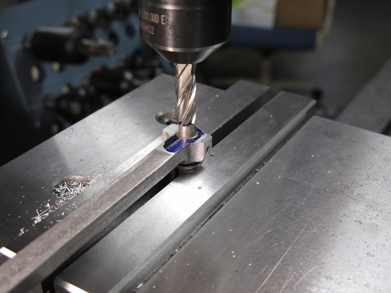
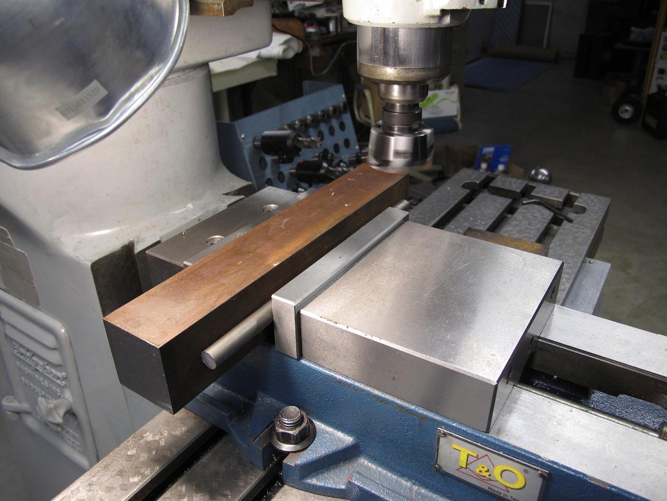
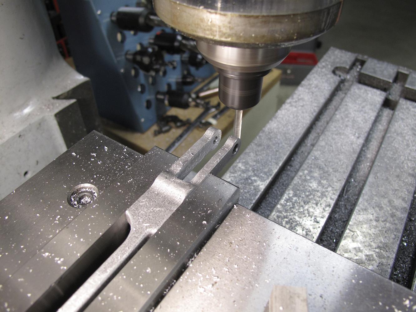
30-July-08 While we had the link in the vise to bore the bolt hole, we moved over .797 and up 3.250 and instead of landing in the middle of the link, we were on…
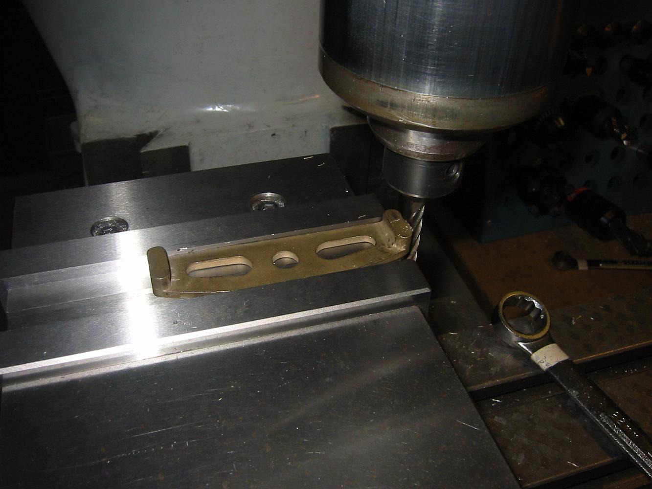
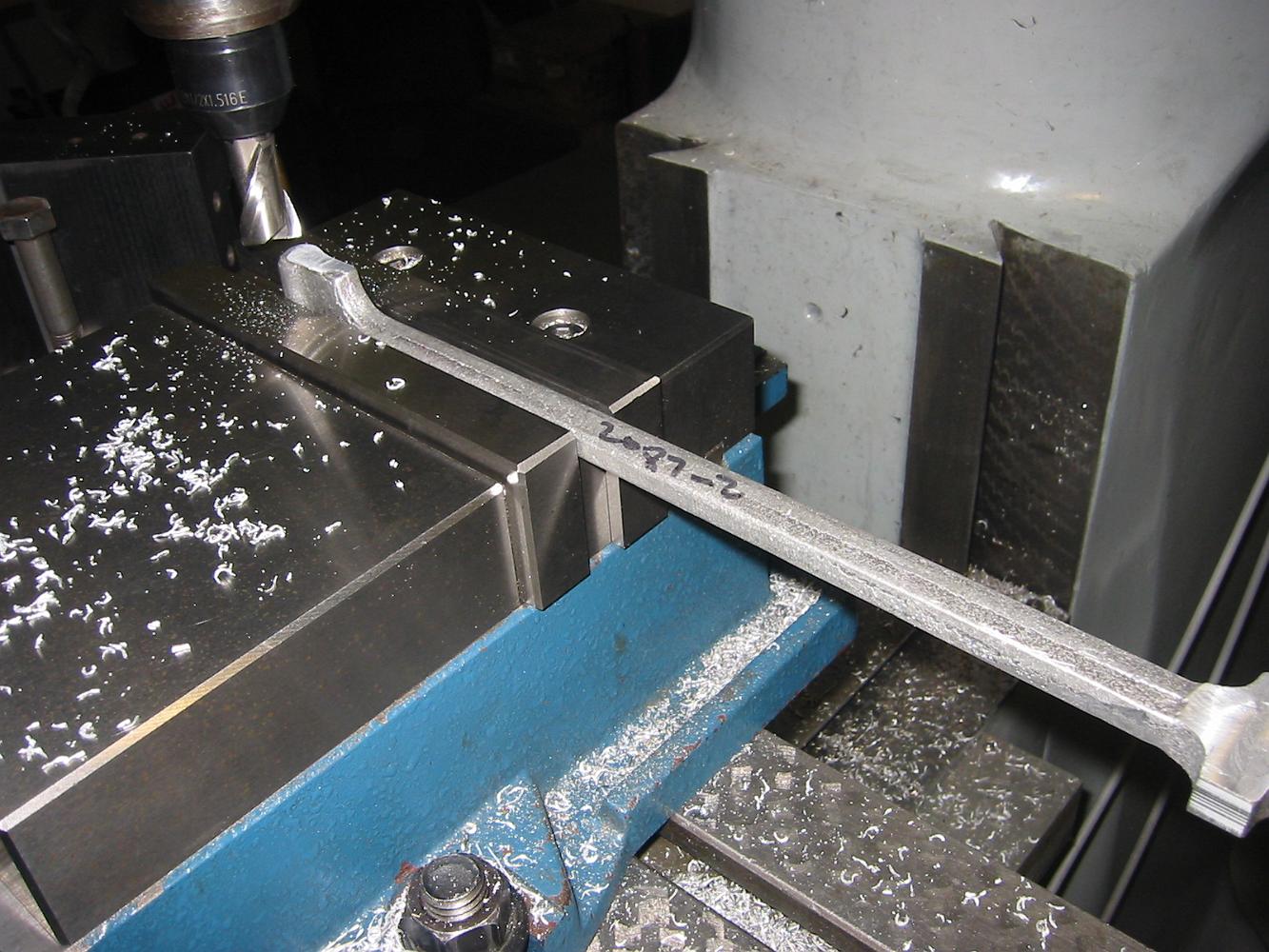
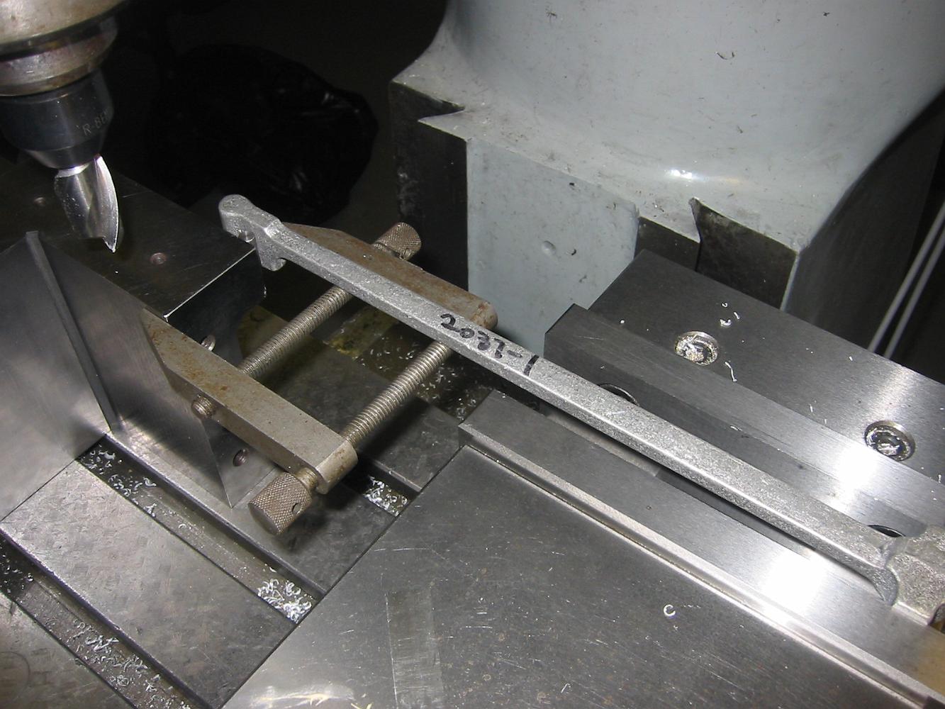
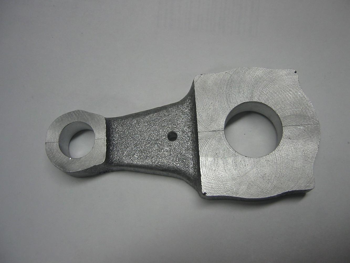
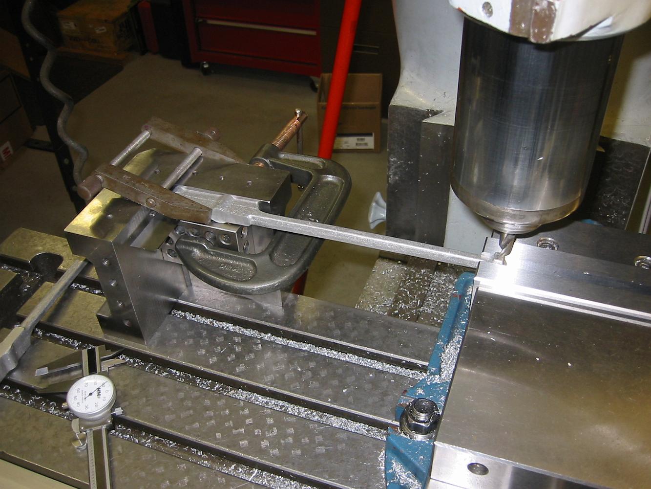
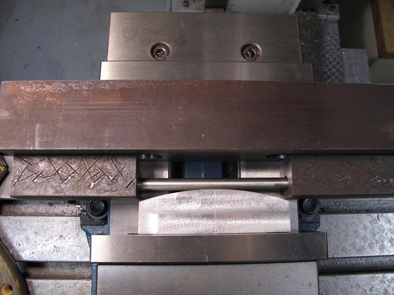
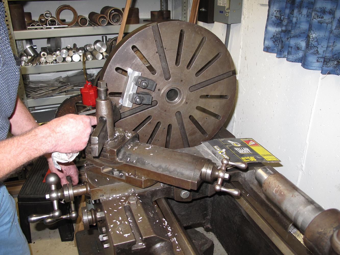
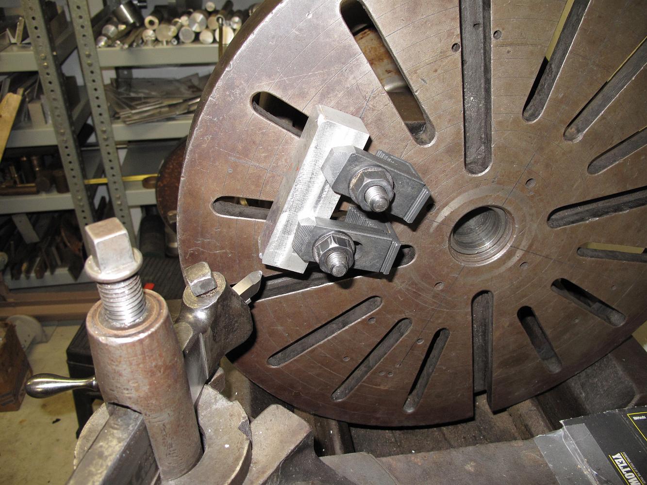
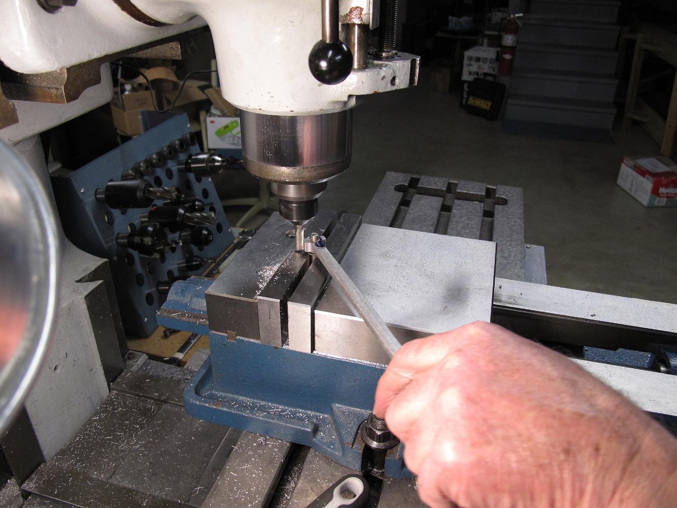
The waterjet process leaves a tapered edge, like plasma or flame cutting can. With the expansion link clamped up, we center on the bolt hole to bore it out.
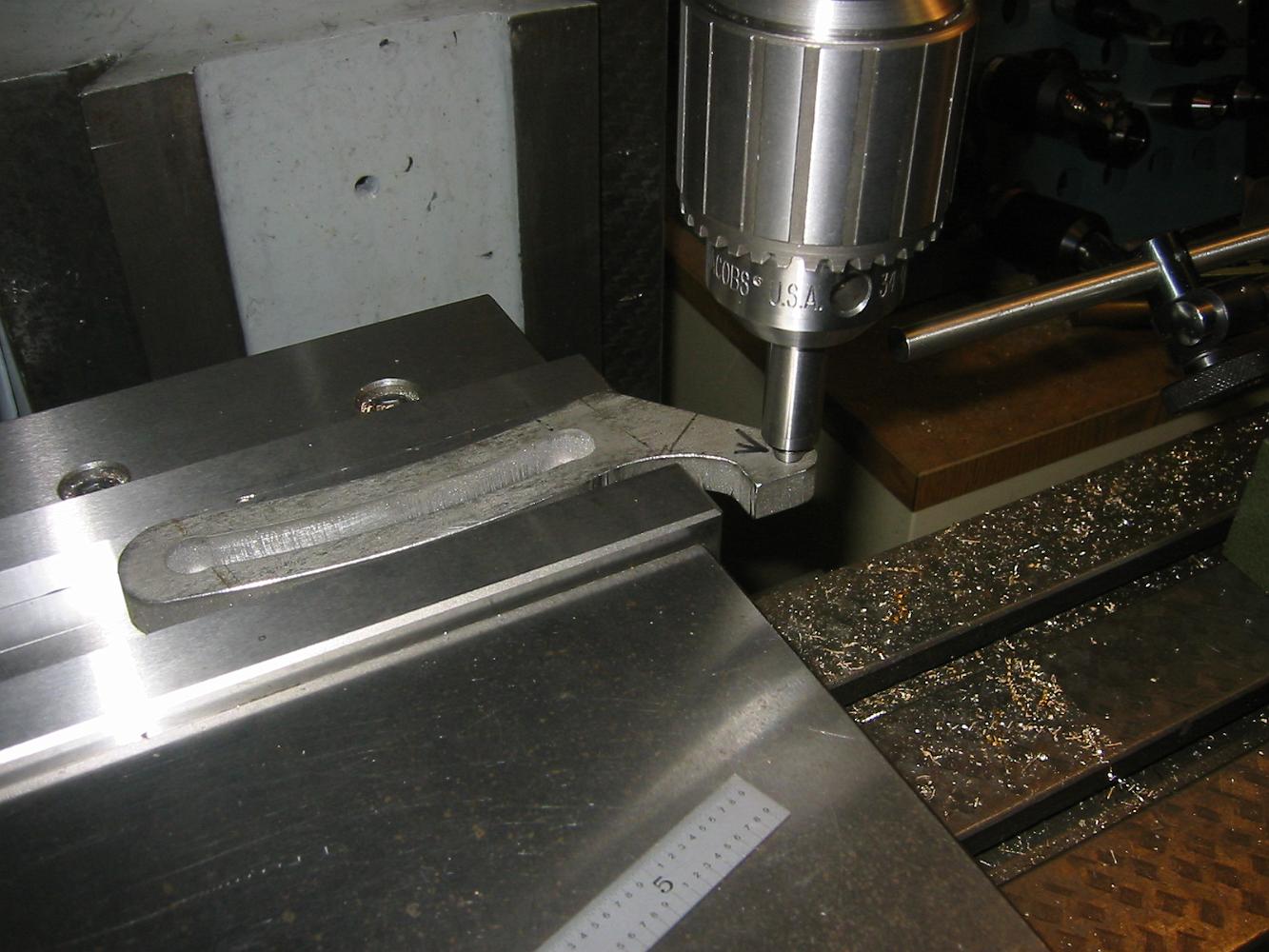
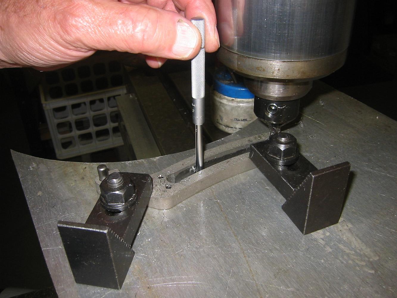
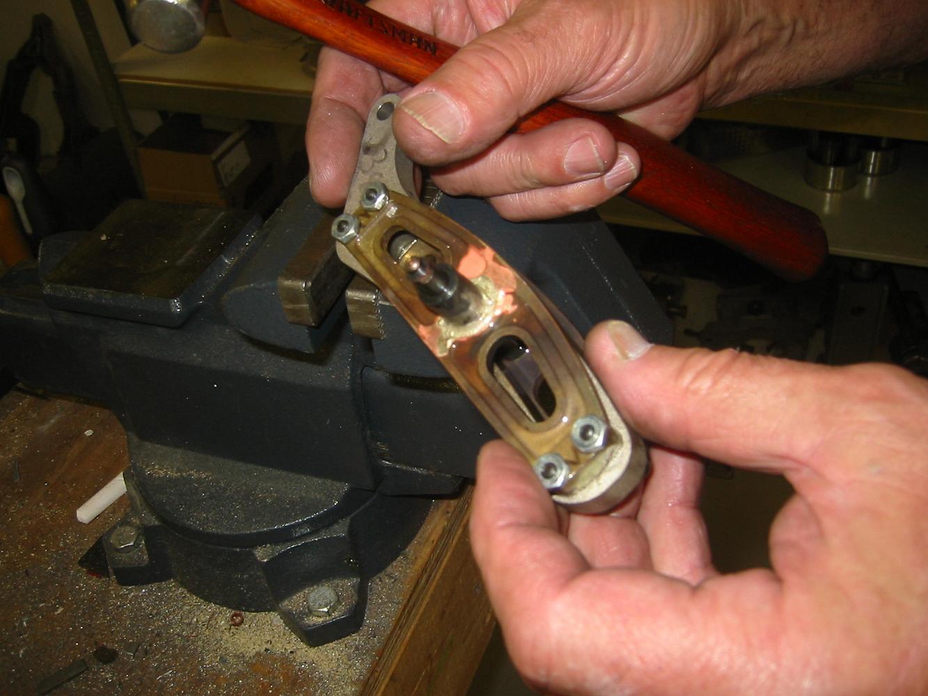
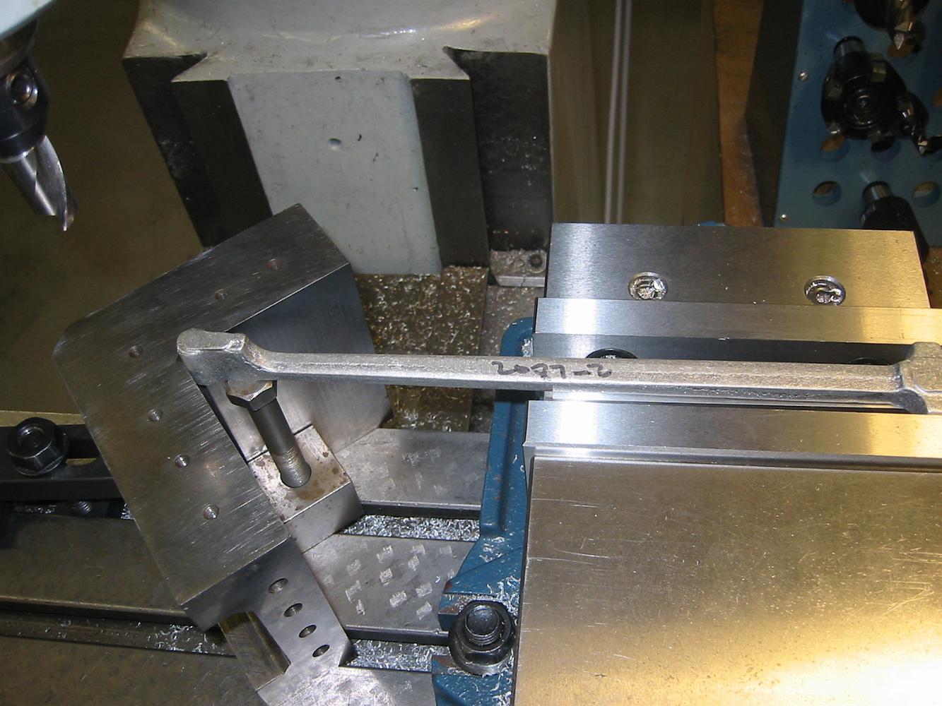
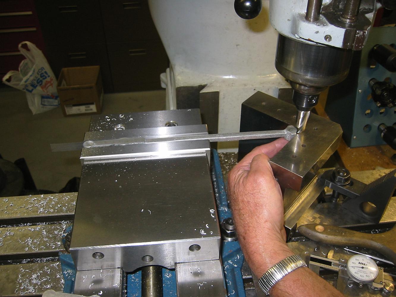
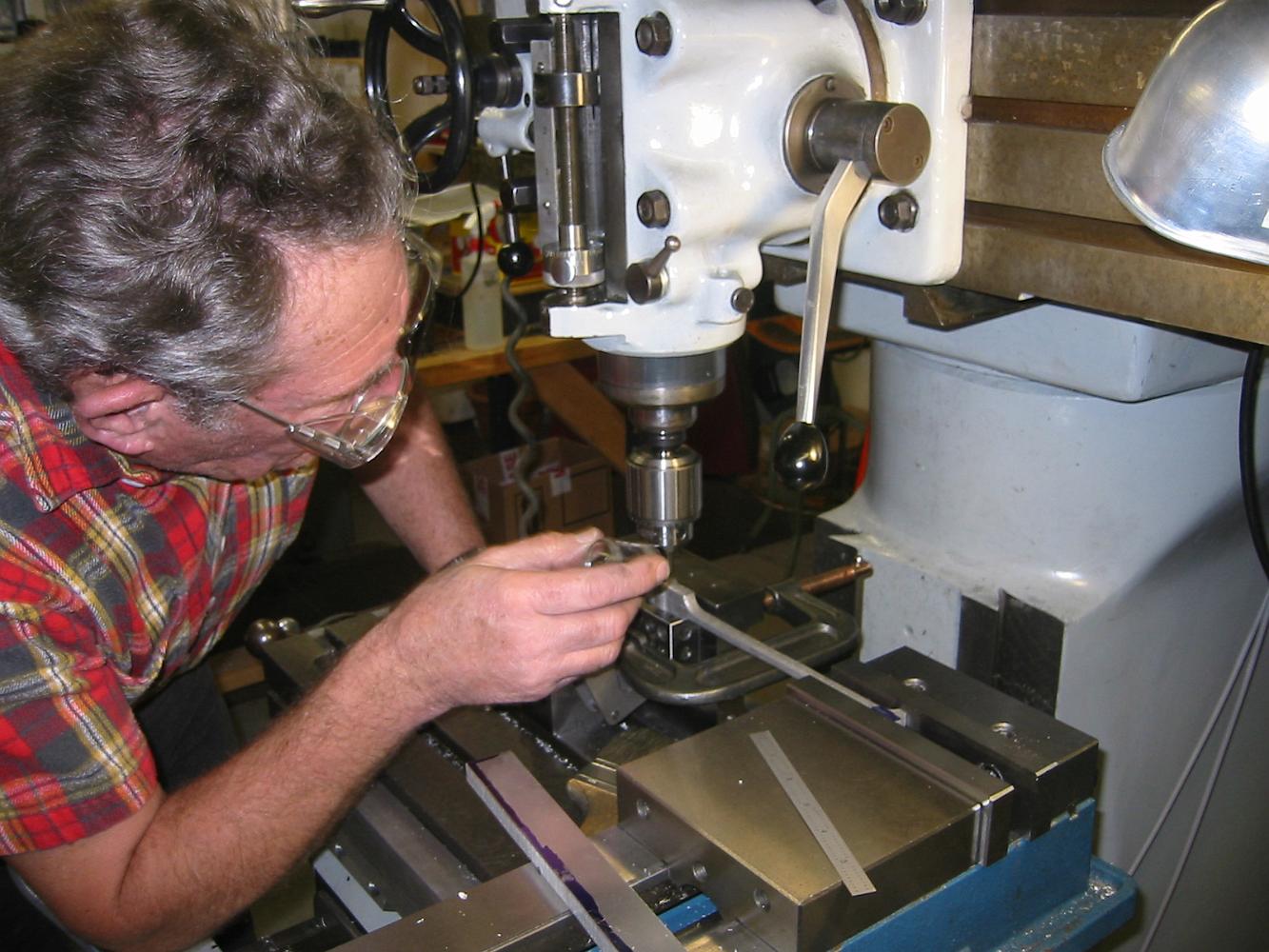
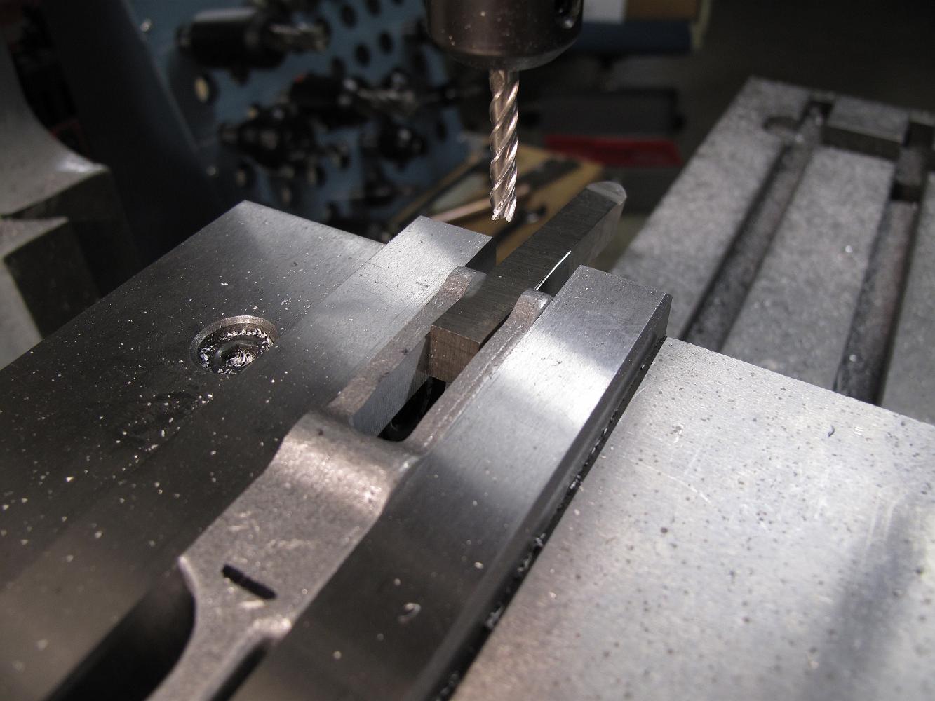
Using a tapered pin to center the expansion link. Two of the links we machined were Tim's. His pieces has a slightly larger slot so we couldn't use the same…
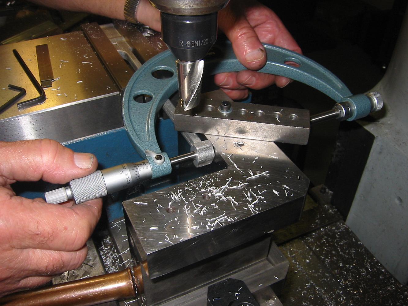
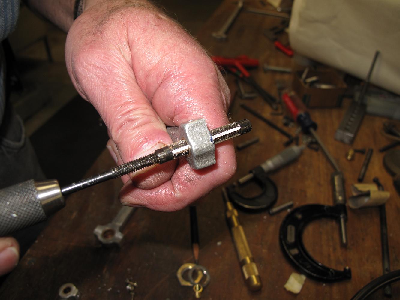
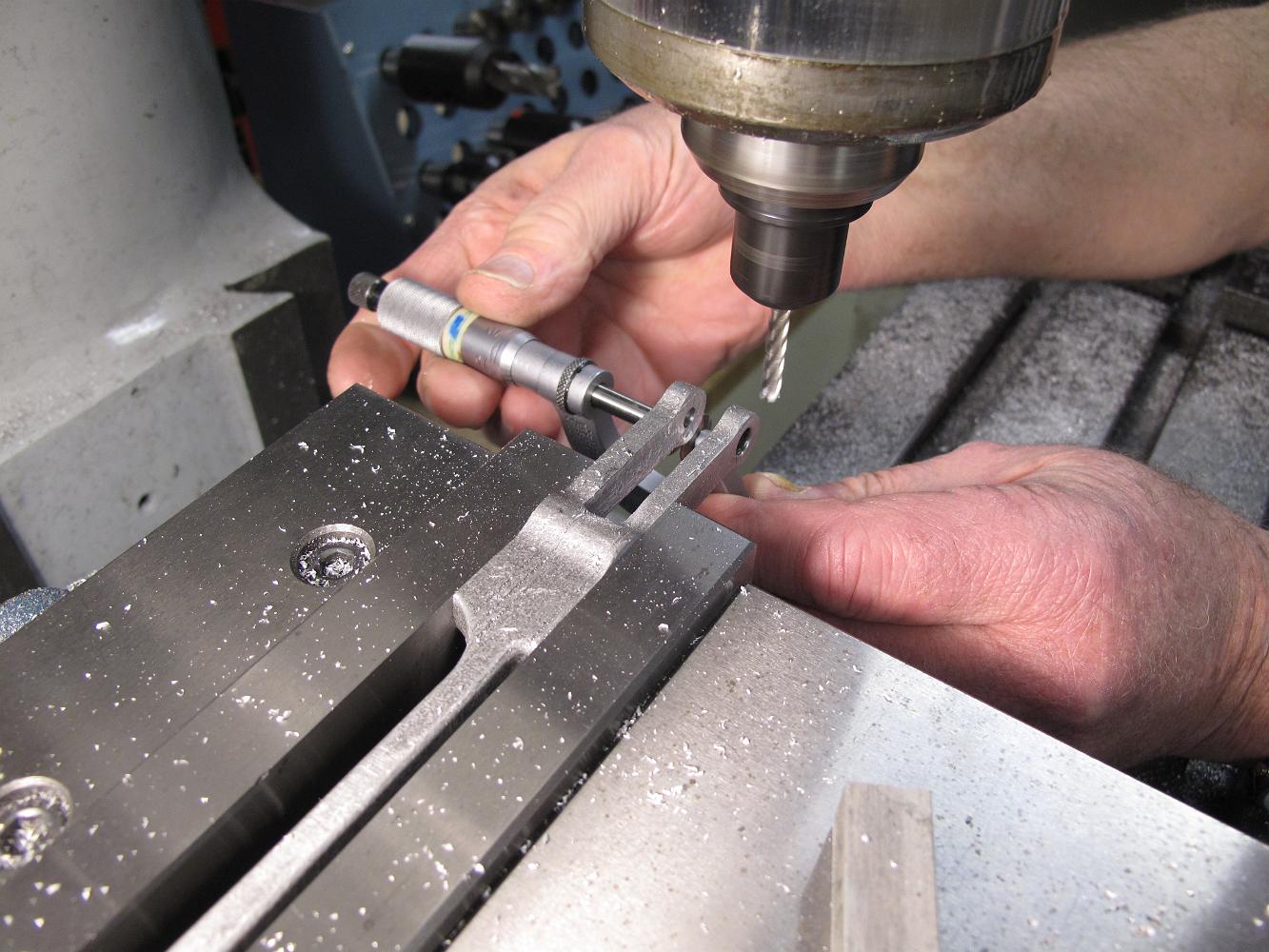
Using a small bore adjustable feeler gage to check the slot width. Tricky things to use because you have to hold them perpendicular to the part in two axis (l-r…
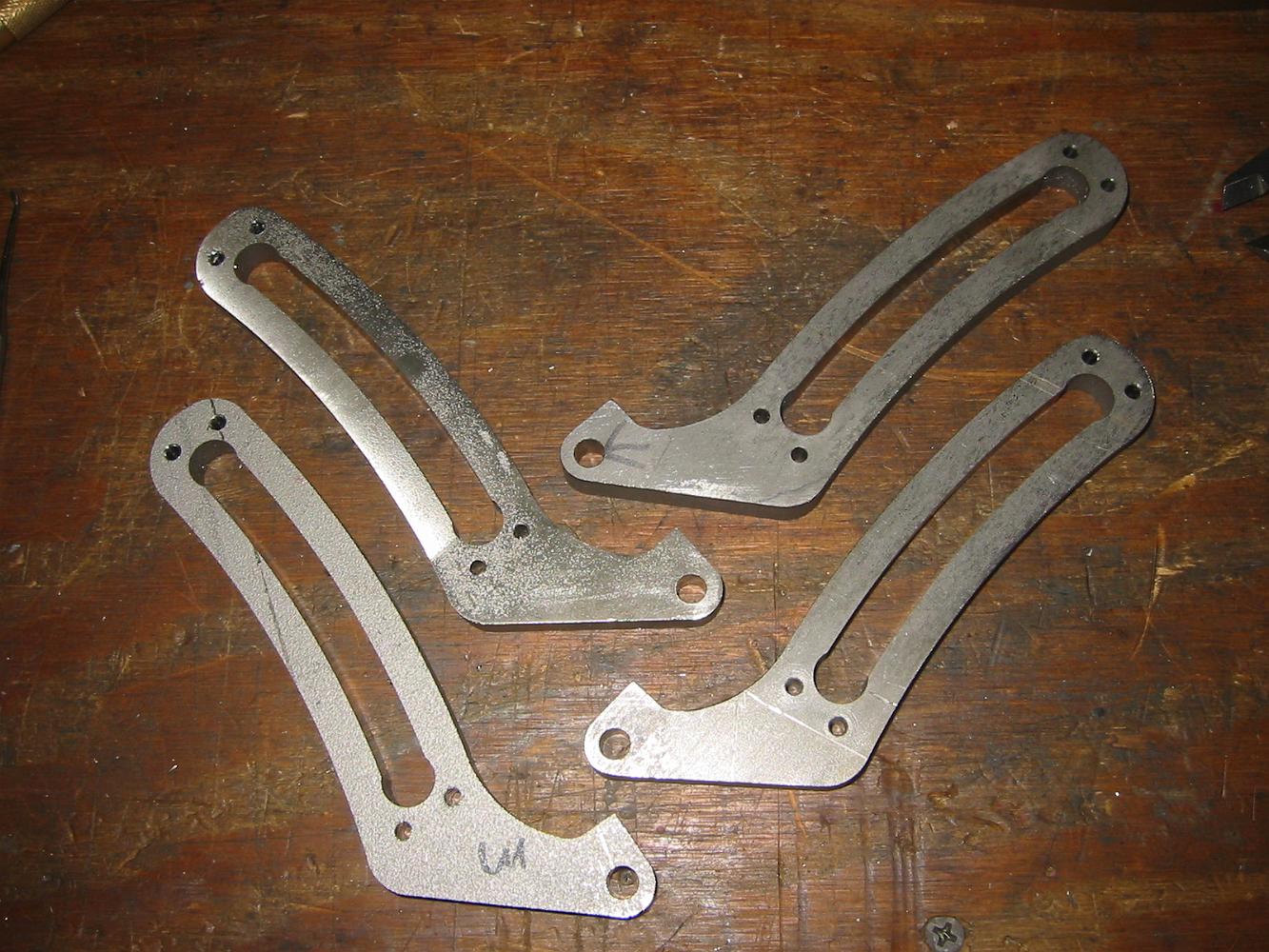
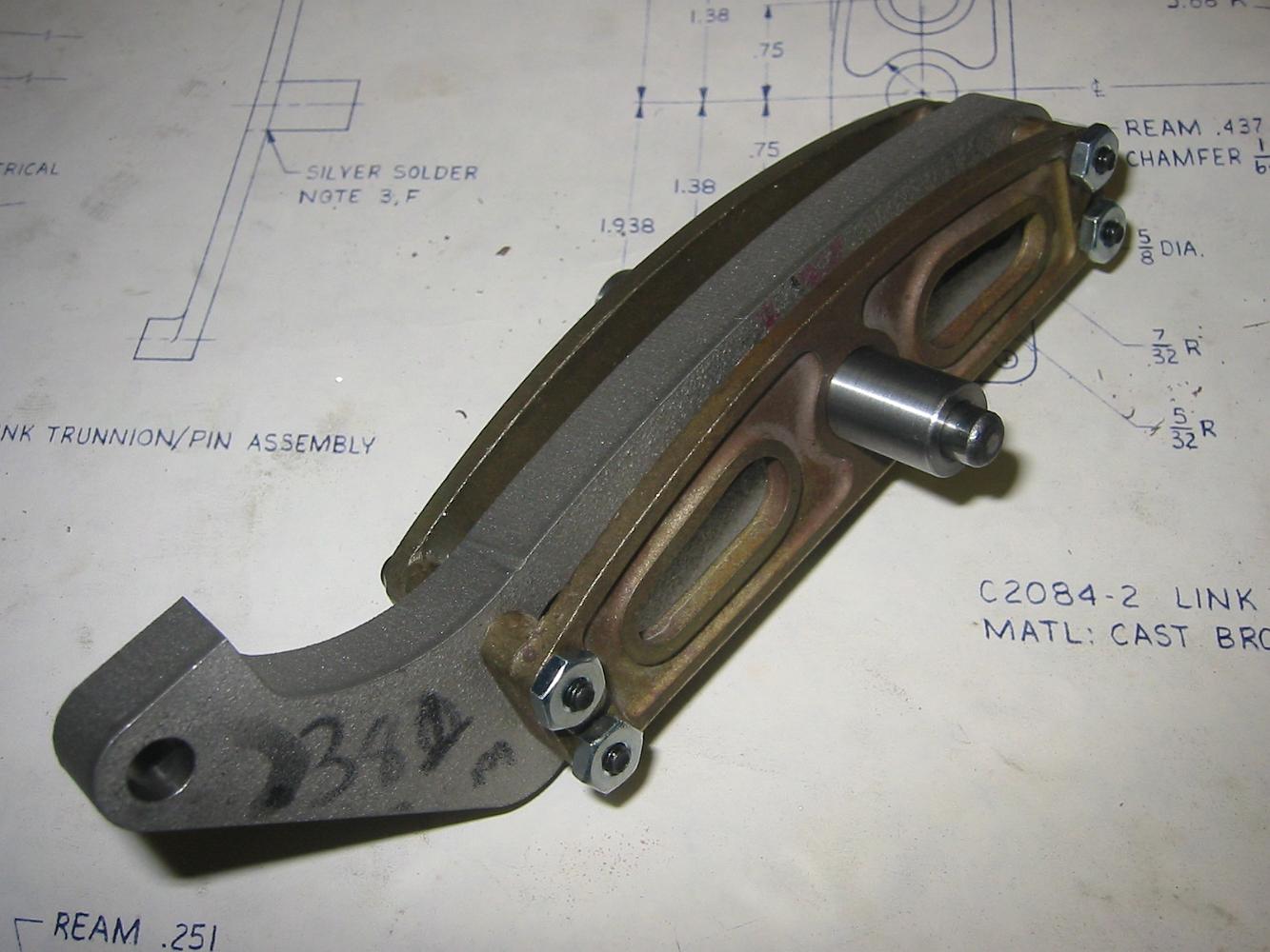
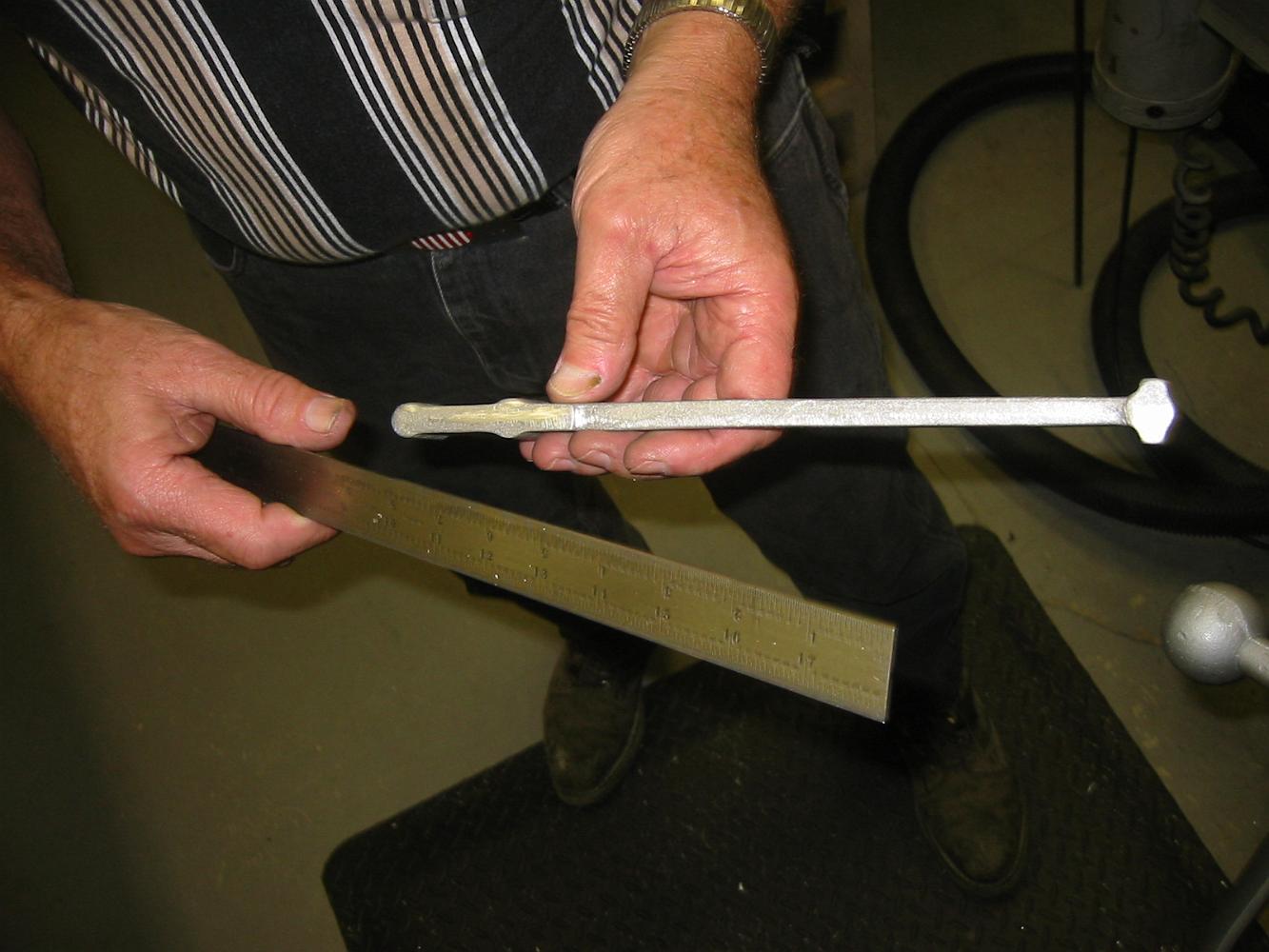
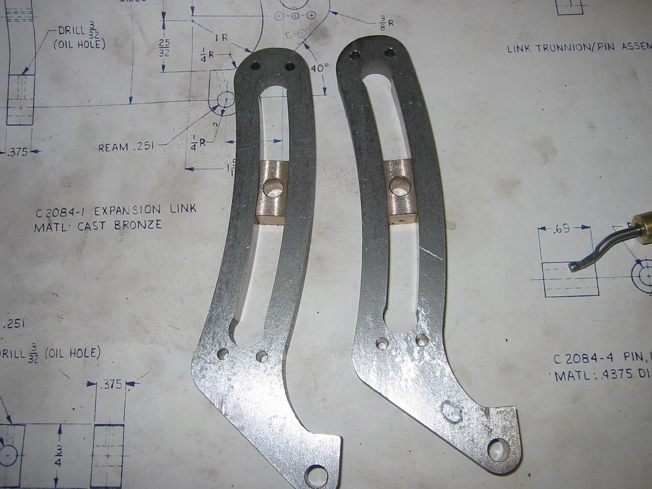
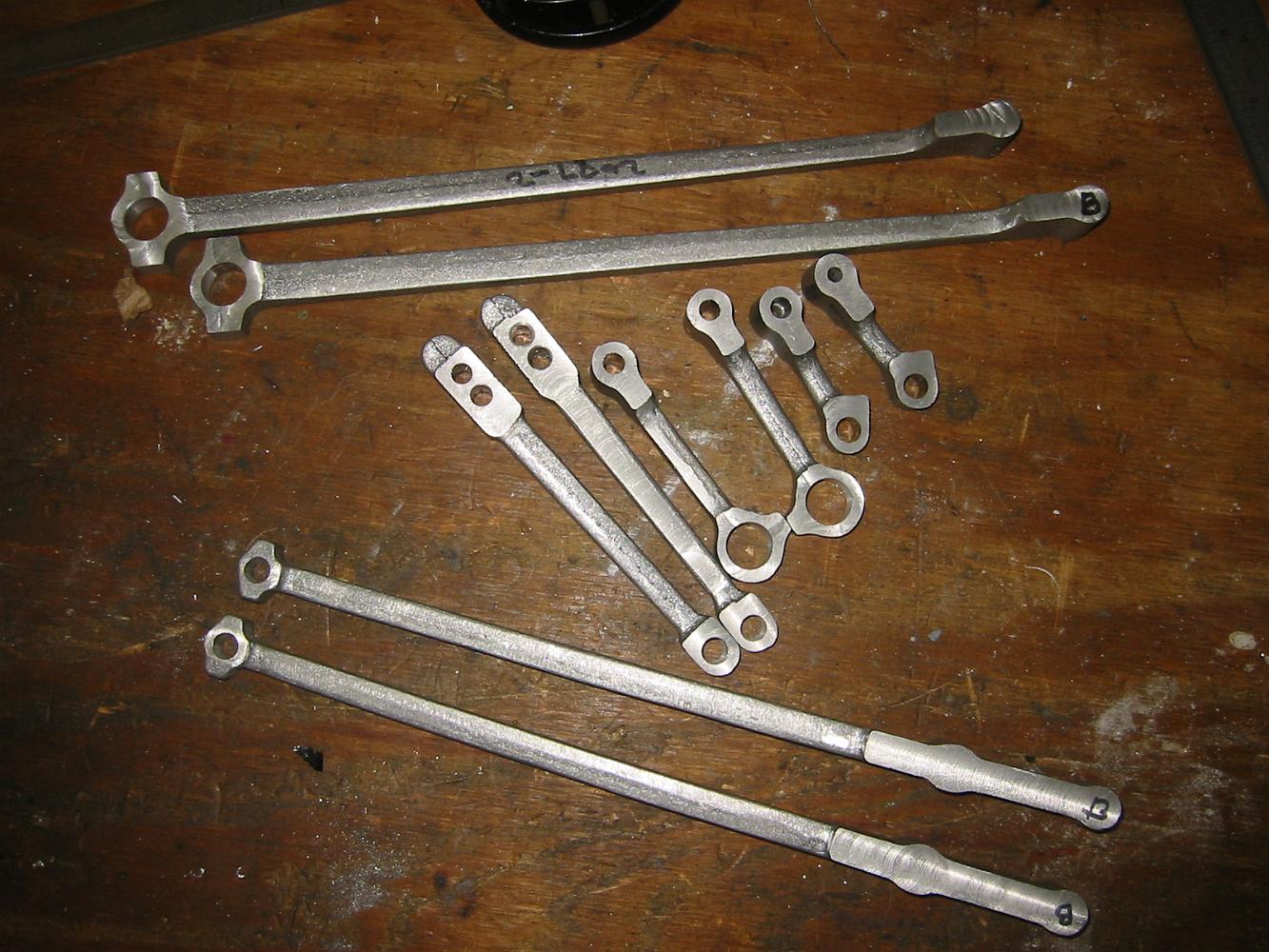
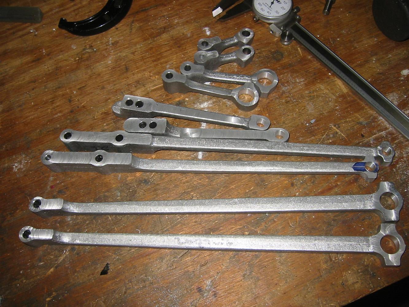
What a nice batch of Expansion Links!
20-Aug-08 Although I only need the two expansion links for my locomotive, I agreed to machine Tim's expansion links since I already had the setup in place. Here…
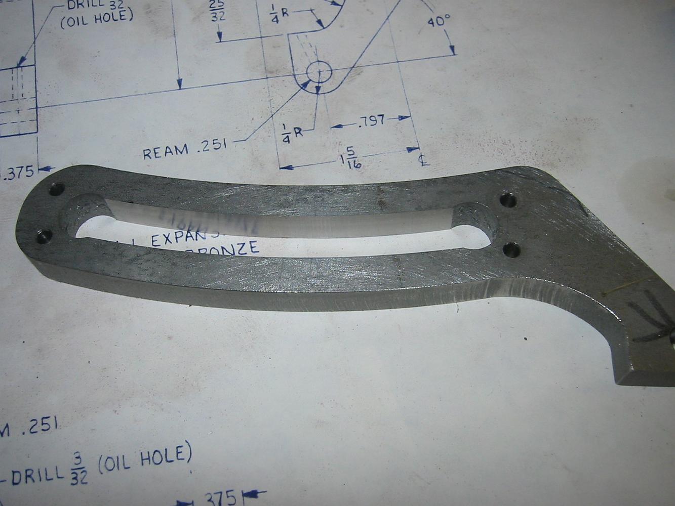
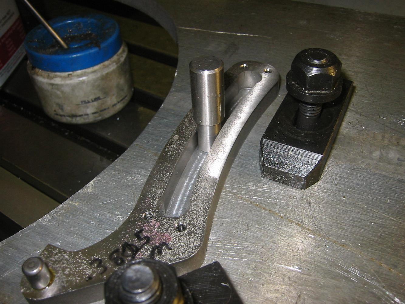
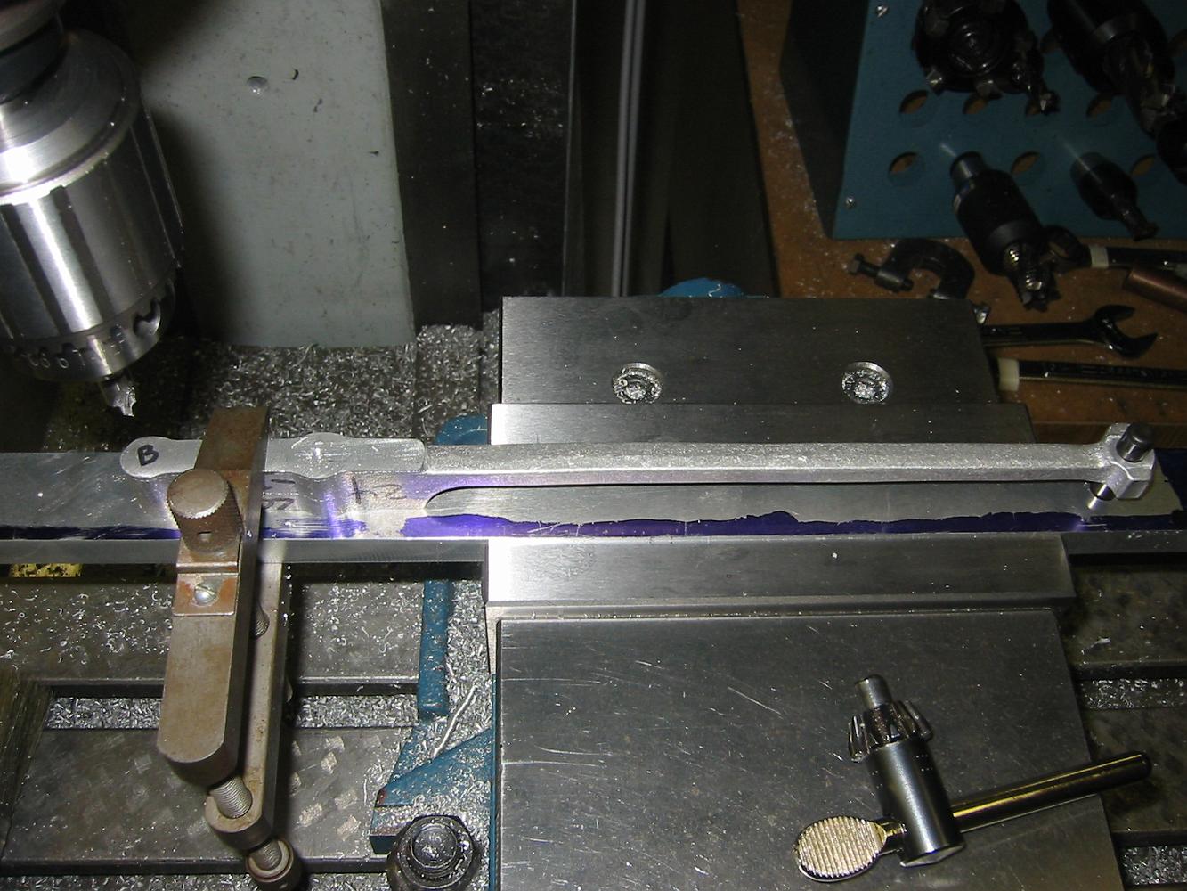
The finished expansion link. I'm very happy with the finish inside the slot - you can see the reflected surface in the picture. A good finish is important since…
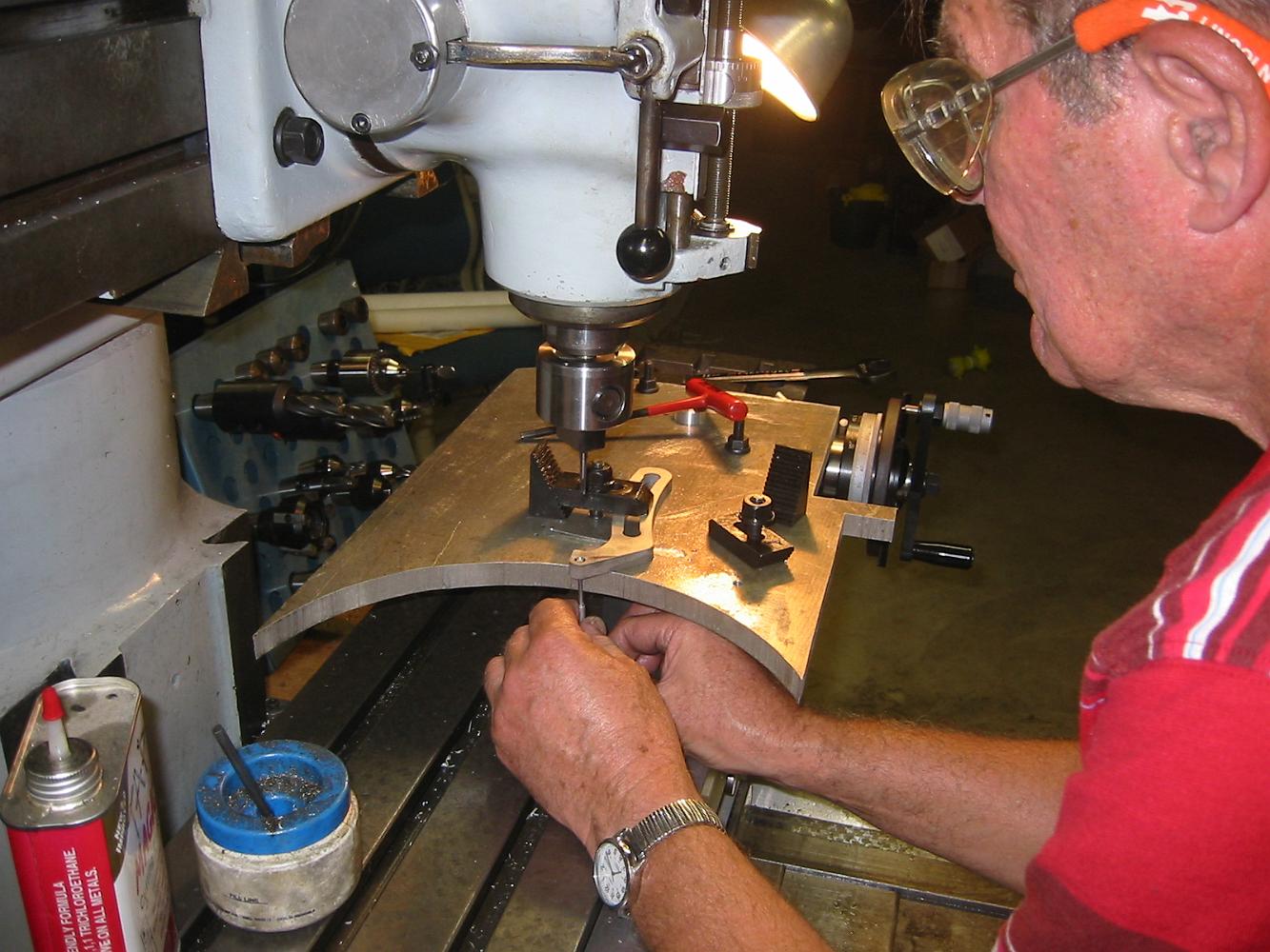
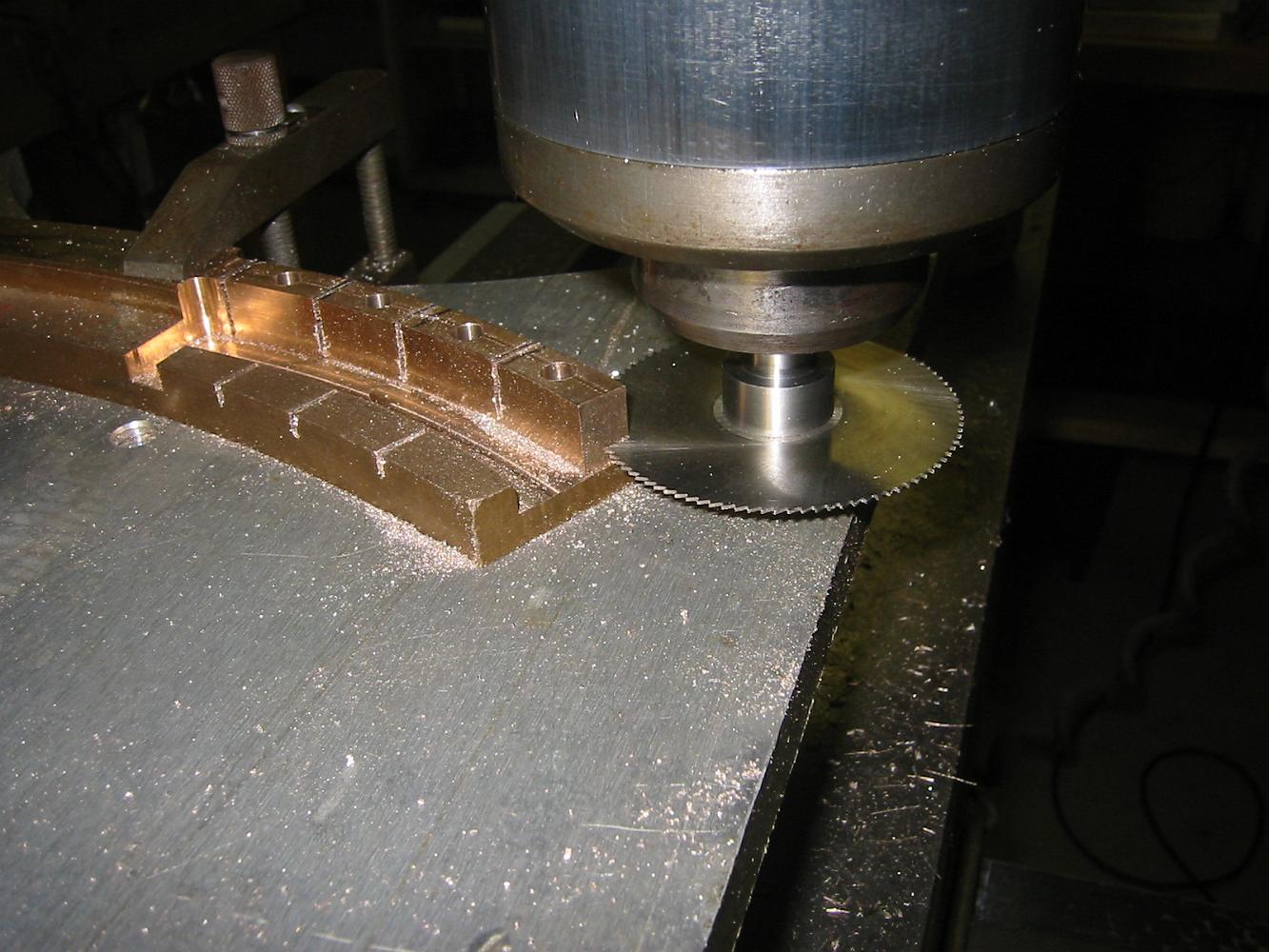
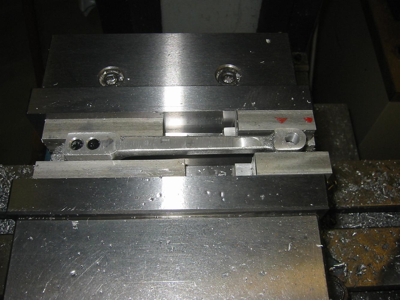
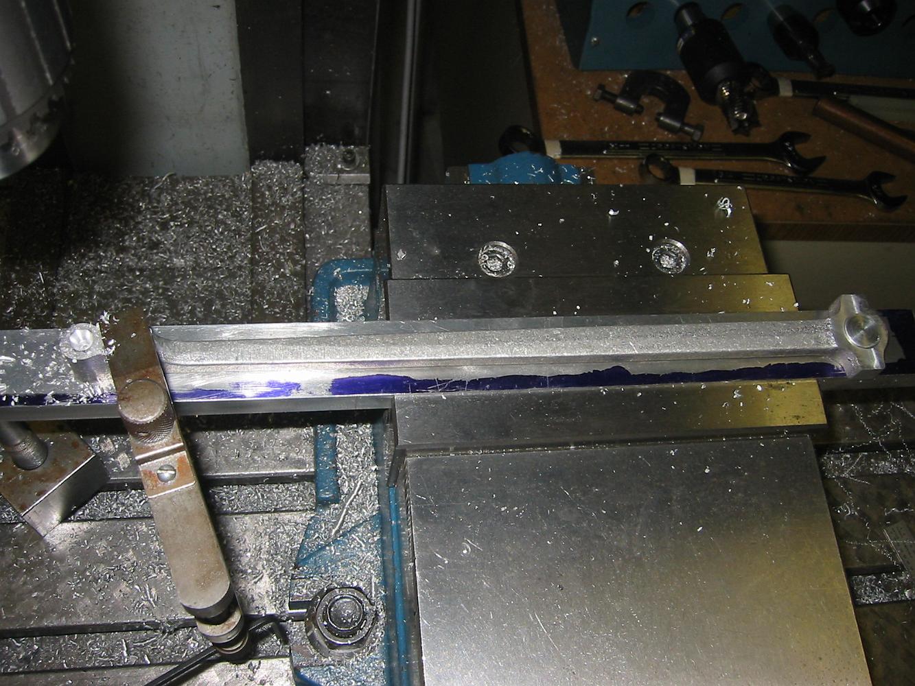
13-August-08 Finish machining the Expansion Link Block slot in the expansion link. We used the table extension on the rotary table to achieve the correct…
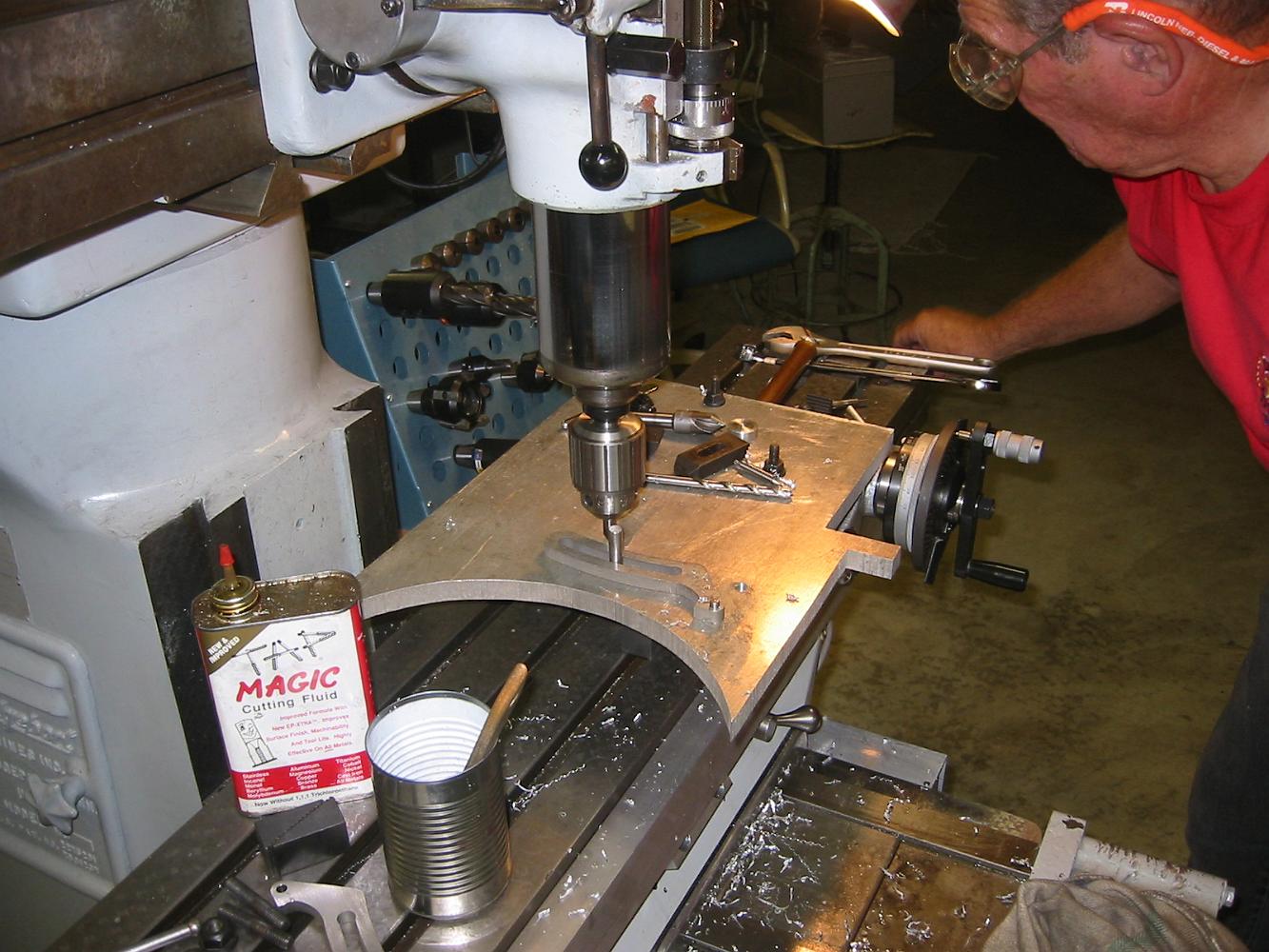
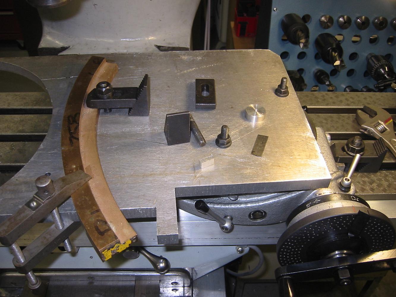
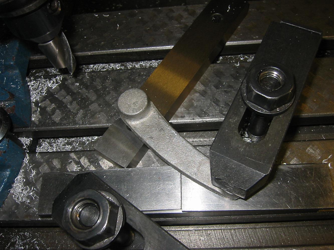
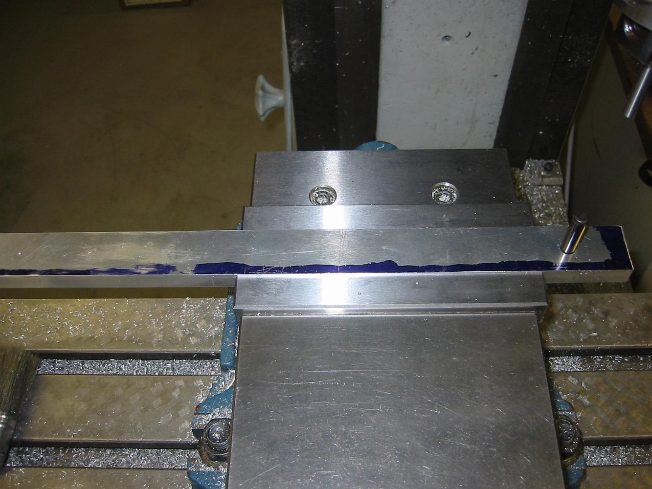
Here's a pretty broad shot of all the tools and support things for this fixture.
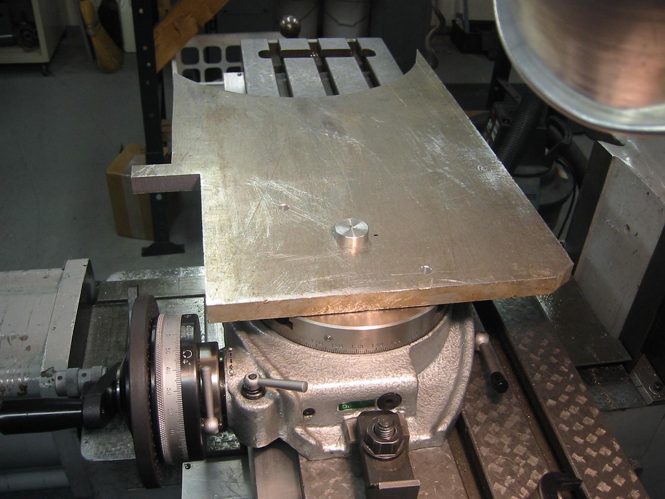
Another part, another fixture needed to hold it! In order to get a smooth and parallel inside surface on the expansion link, we build an extension table on the…
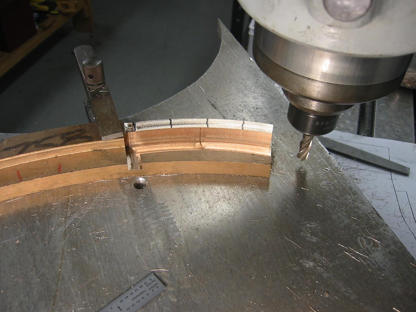
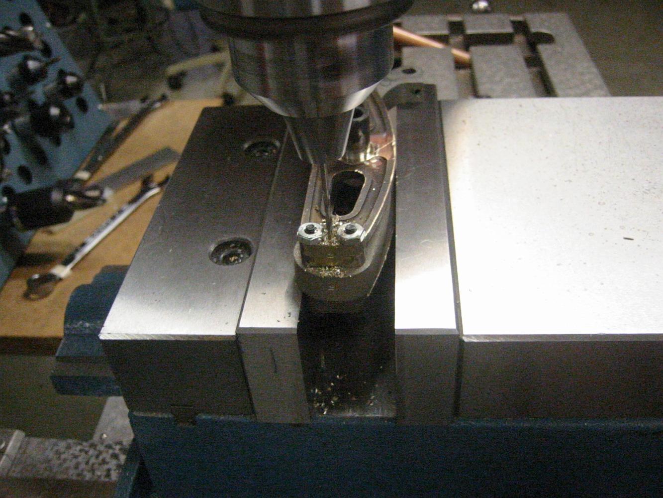
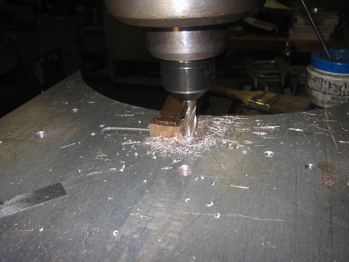
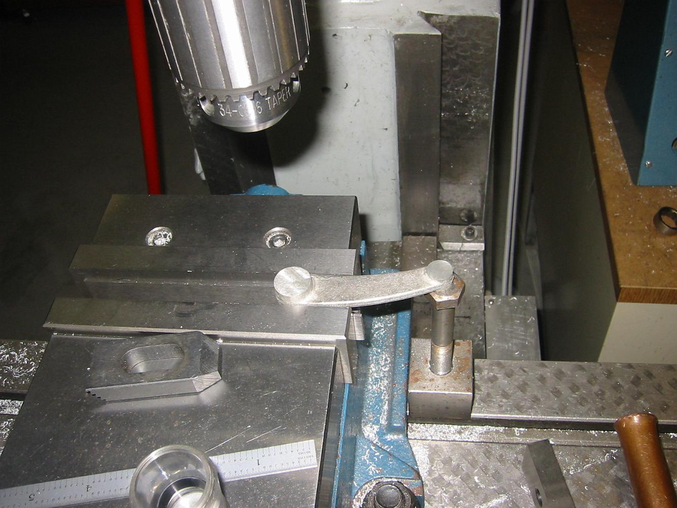
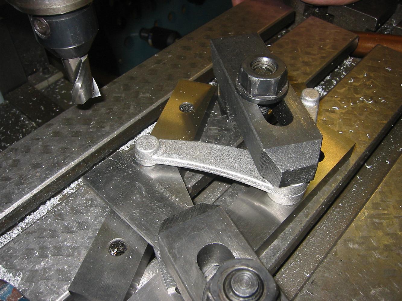
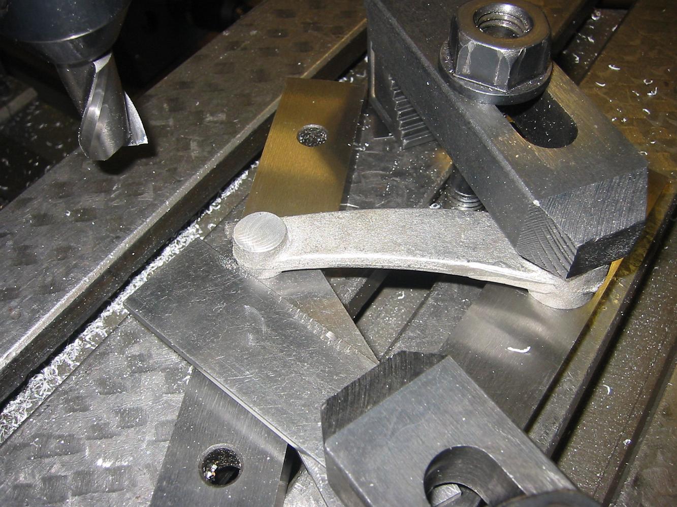
27-Aug-08 Cutting the link blocks from a piece of bronze.
With the stock clamped down, a skim cut is taken from the top to true it to the table surface.
27-Aug-08. Without disturbing the table, we re-use the same setup from the expansion links to cut the link blocks. The bronze stock is clamped to the table and…
23-Sept-08 One last thing - drill the roll pin alignment holes and now the parts are ready for paint!
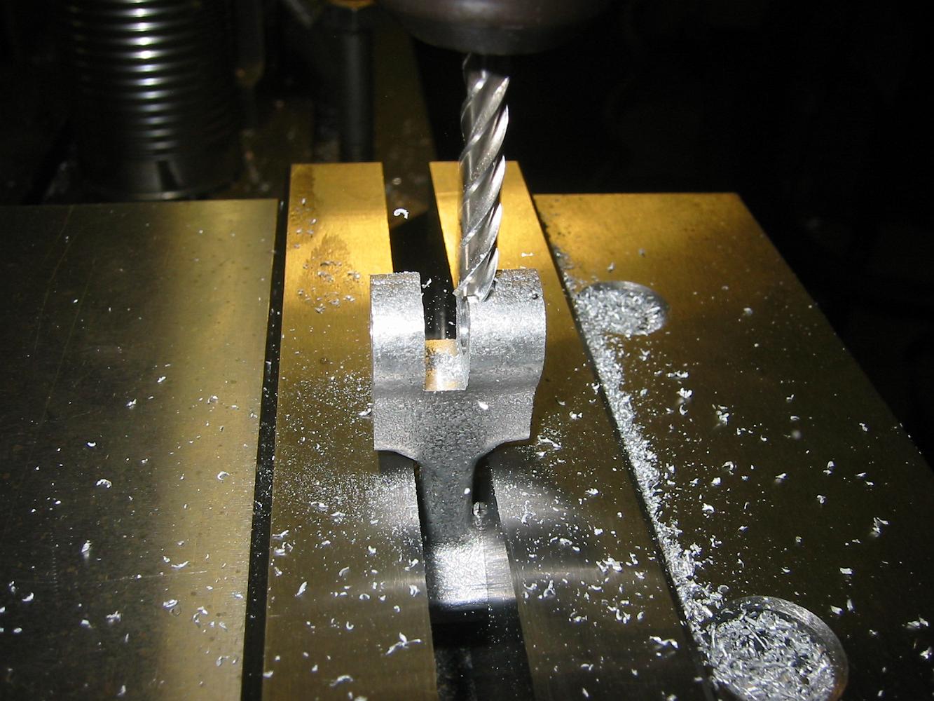
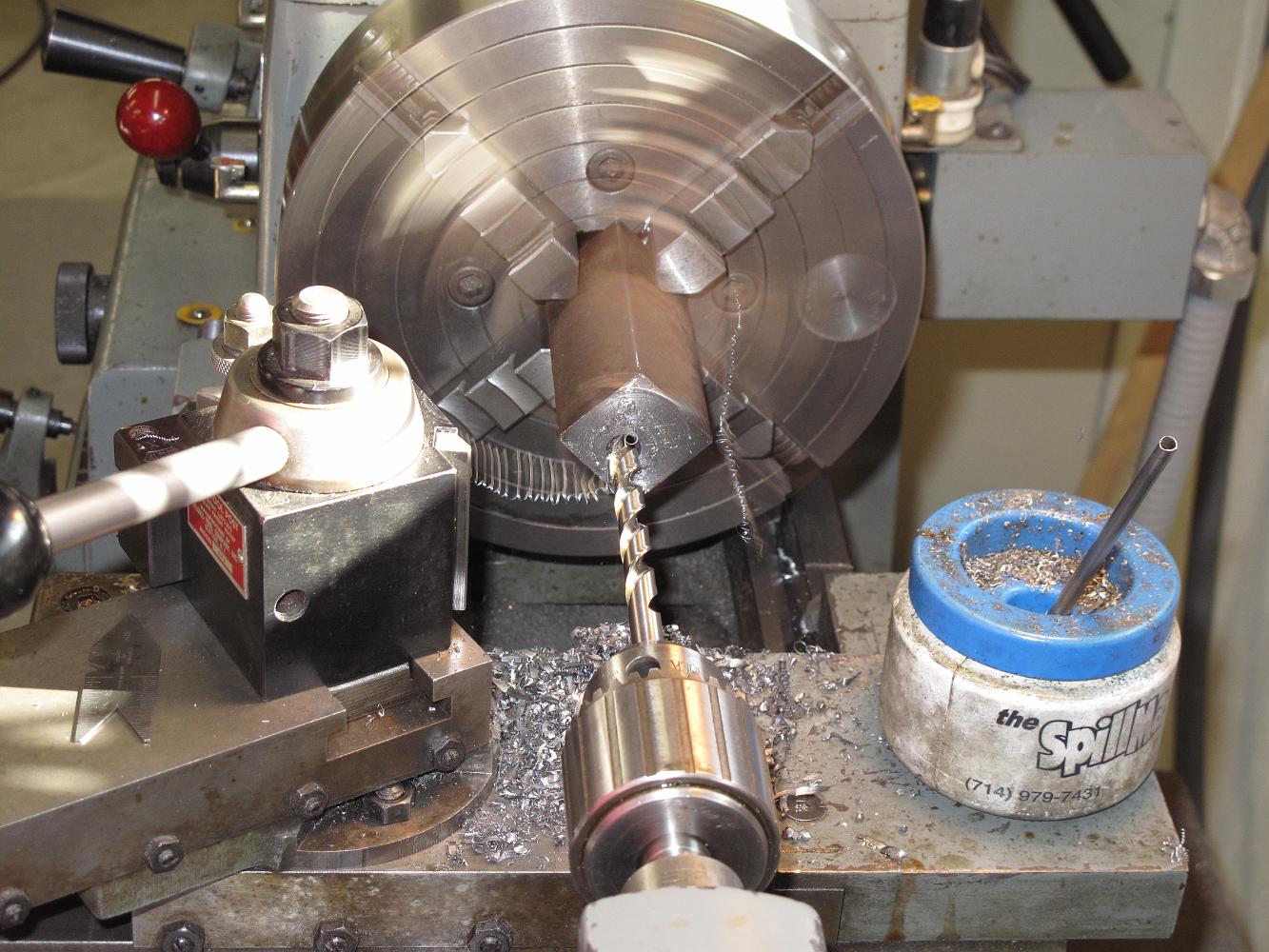
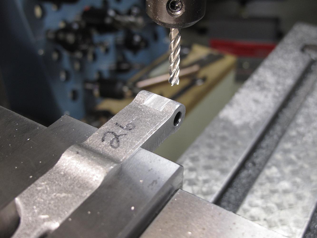
Using a larger end mill to enlarge the hole and speed up the next boring operation.
16-Sept-08 Four sets of trunion blocks. Two for me and two for a friend who is also building a mikado.
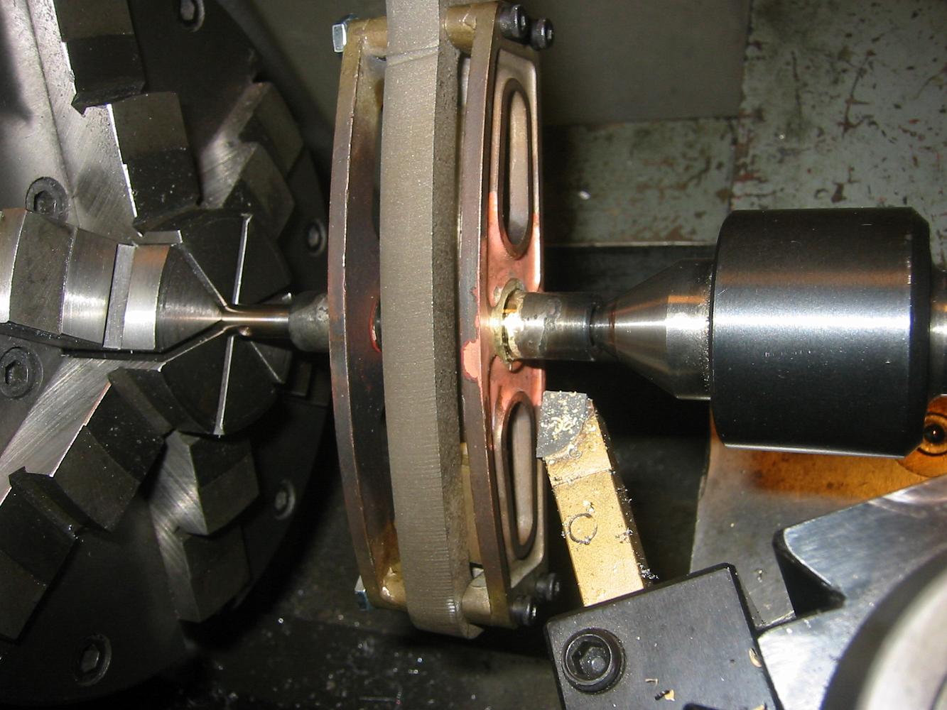
16-Sept-08 With the trunion gently pressed onto a pin held in the chuck, and the live center holding the other end we machining away the excess and lumpy solder…
By the time we got to the last one, My silver soldering skills had improved. Here I've hardly wasted and silver but have a nice neat joint.
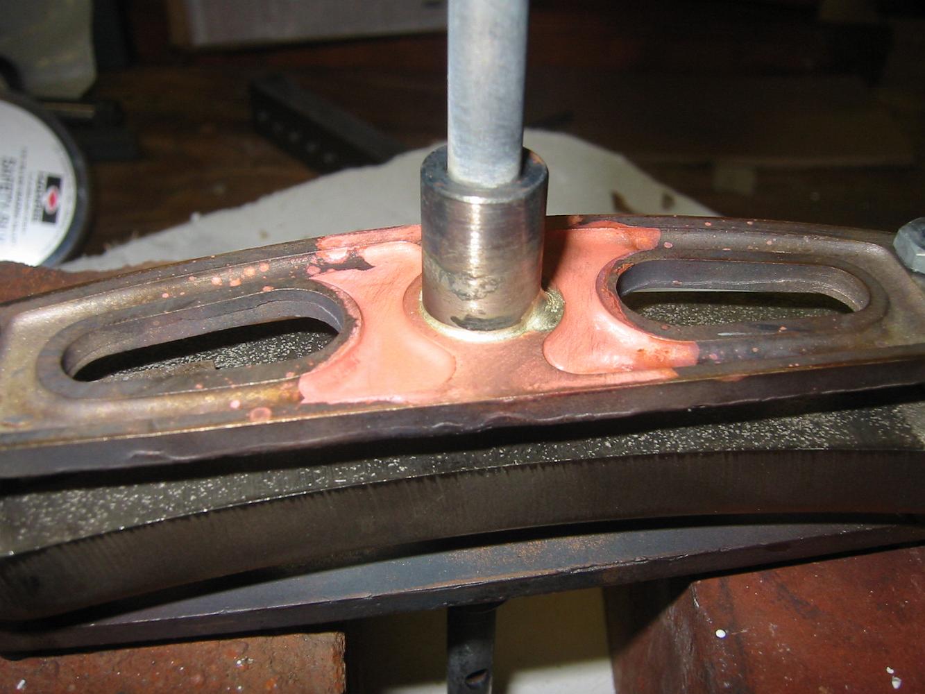
The silver solder filet looks okay, but I'm still having trouble getting things hot enough with the plumbers torch and MAPP gas.
16-Sept-08 The results after silver soldering one: the alignment pin is stuck. After removing the pin with a hammer, we think this very close fitting pin…
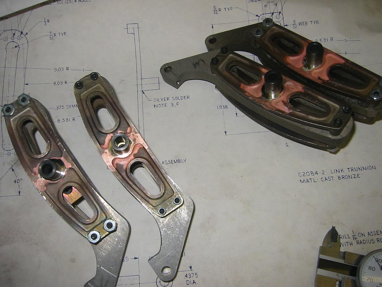
10-Sept-08 Assembled Expansion Link assembly. The 1/4" dowel pin fits through the trunion pins and the expansion block, so we much have machined it correctly!…
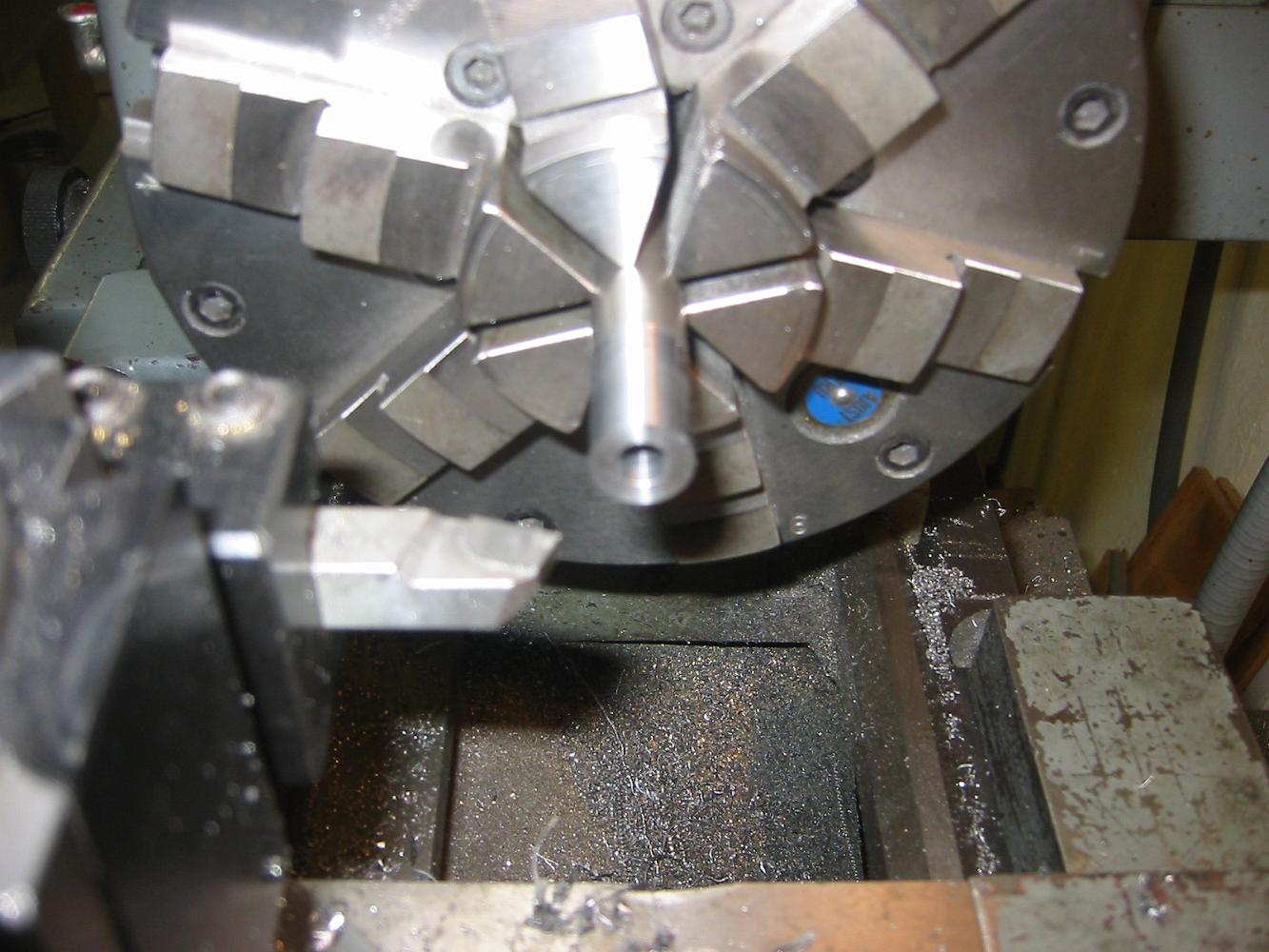
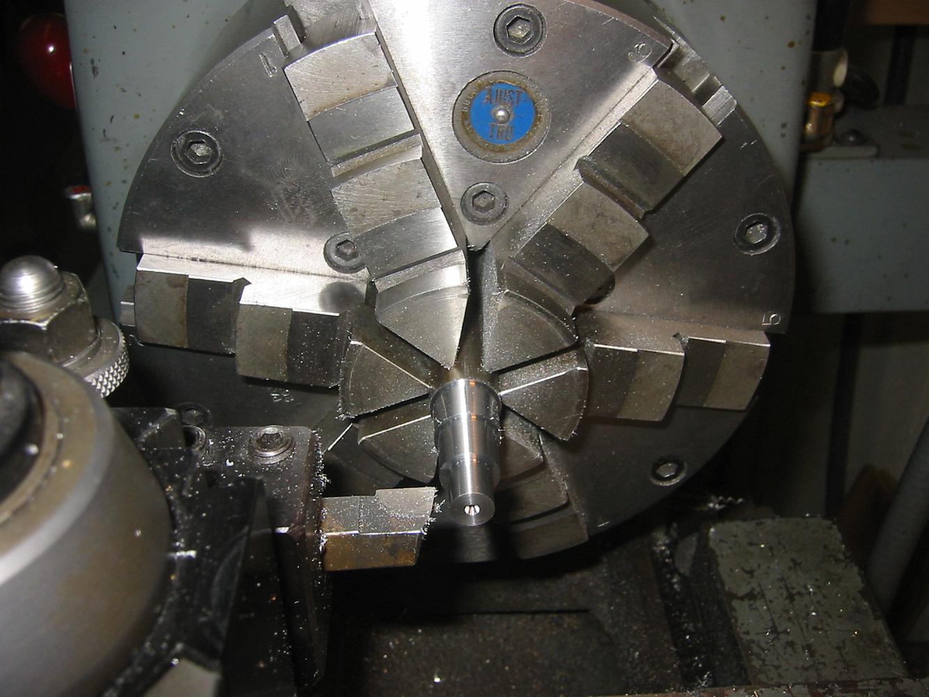
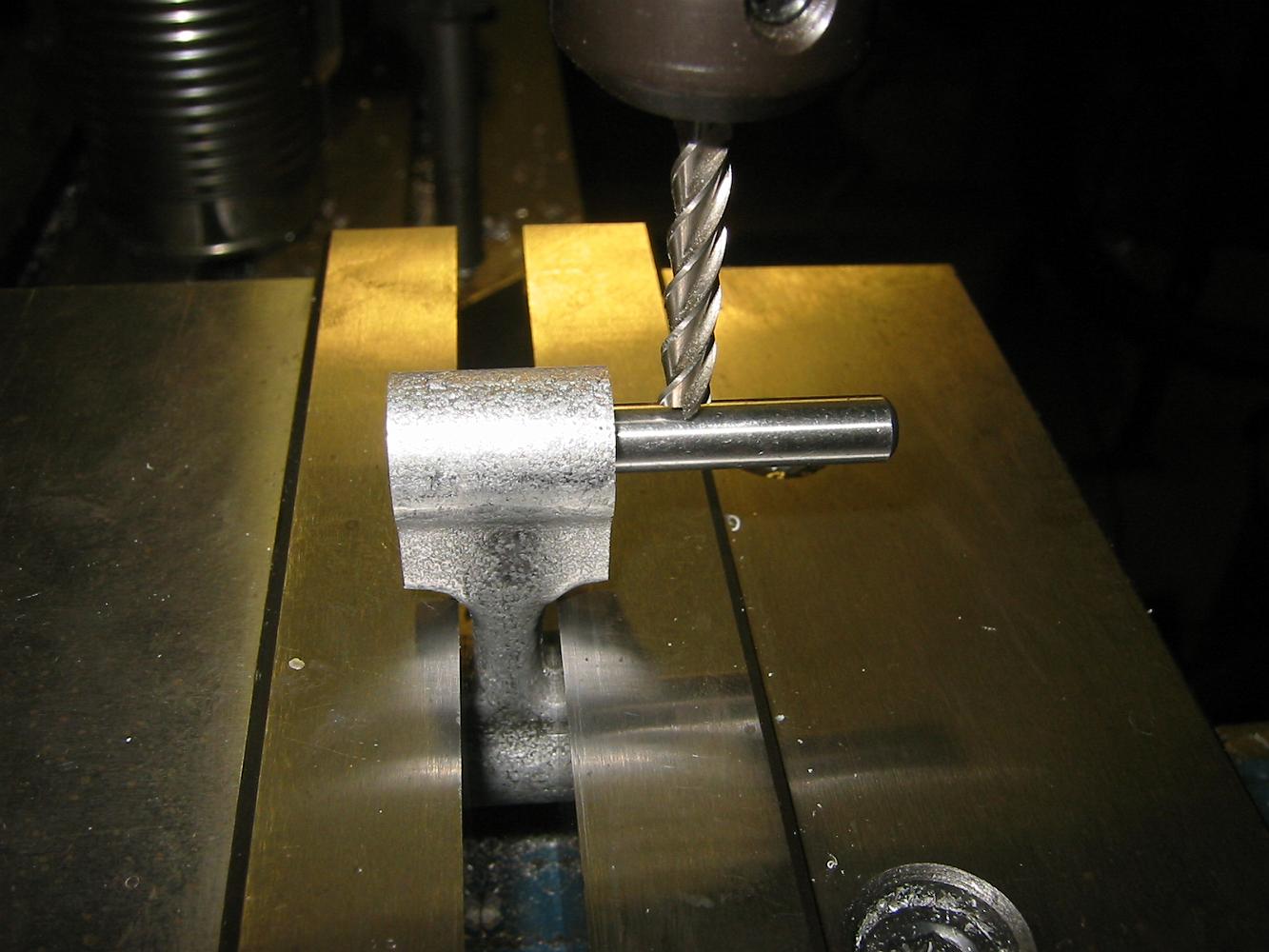
10-Sept-08 Turning the trunion pins from oversize 7/16" stock and not the 1/2" drill called for in the print. "This way," Bill explained, "the 1/4" hole bored…
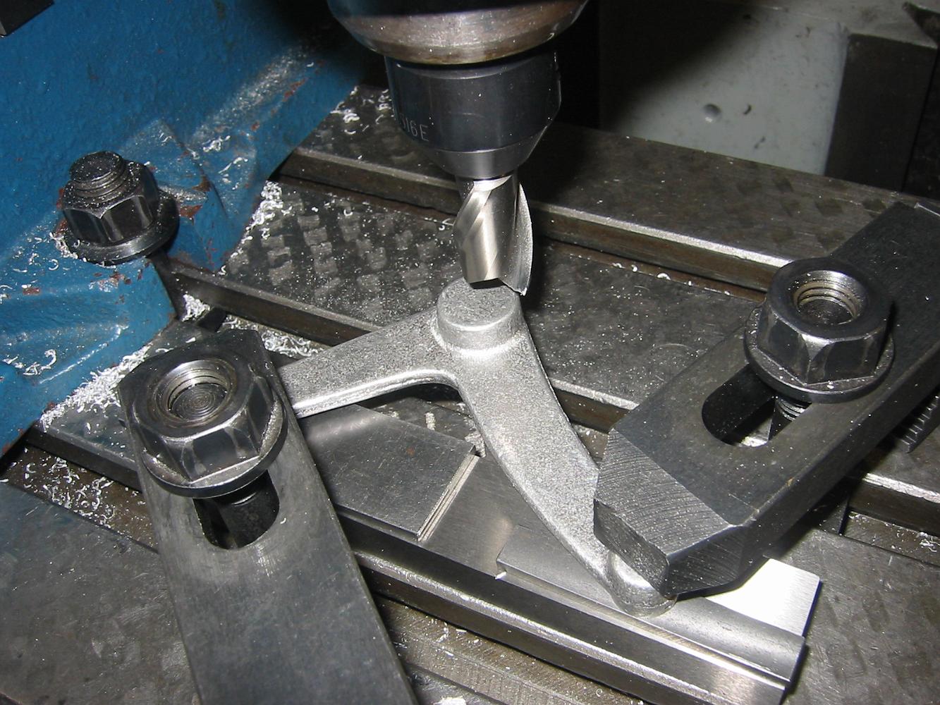
The completed milling operation on the union link. Unfortunately we machined away the rod detail on the casting, it looks like one continuous piece without the…
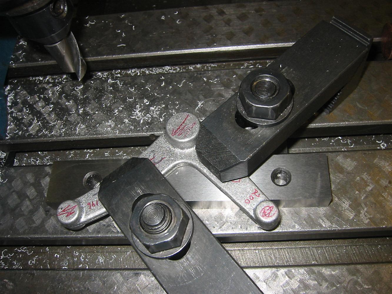
With the union link flipped over and the machined surfaces on a parallel, we machine the other side.
Union Link: like every casting, the first step is establish a machined reference surface. We decide the backside of the link will be ours.
We finally resort to clamping the combination lever in the vice. It is setting on a parallel and pinched between the vice jaws with two pins to insure a good…
29-Oct-08 Holding the end of the combination lever, setup number 2. With the inside corner angle plate confining the left-right motion and a jack screw to keep…
Taking a guess where the relative centerline is inside the casting, we machine the rod end to one-half the finished thickness. Now with both ends having a…
With the rod end machined, setting on a parallel and clamped in the vice, we need to machine the other end. We first try clamping it against the angle place and…
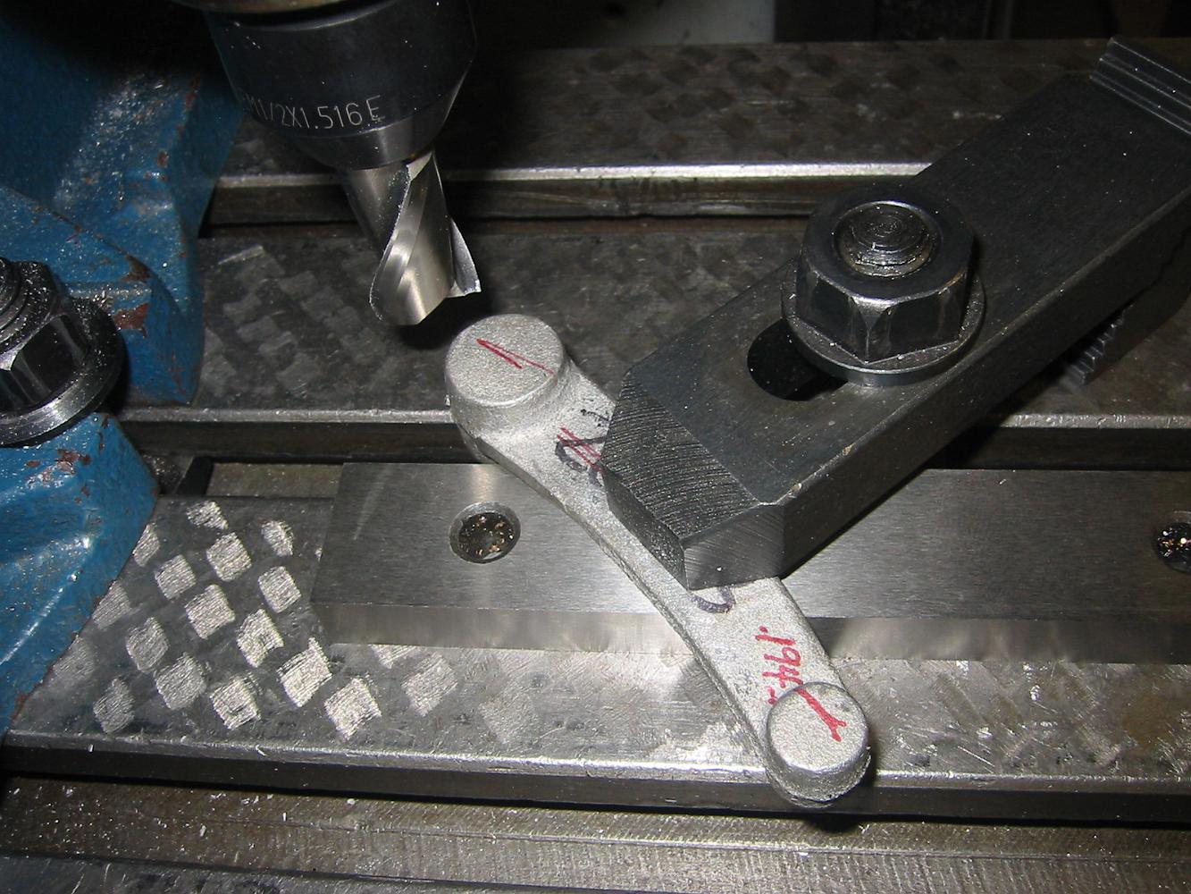
29-Oct-08 Next: How to machine the Combination Lever. Trusting the part is relatively straight along the casting parting line (the drawing show it as straight),…
?Are we there yet? How to measure the thickness of a part without disturbing the setup - measure over the whole thing and subtract the angle plate from the…
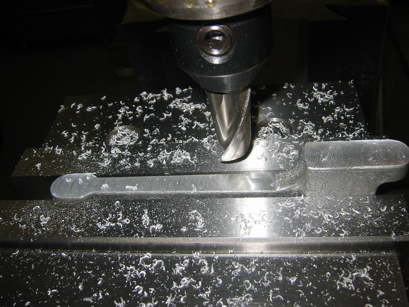
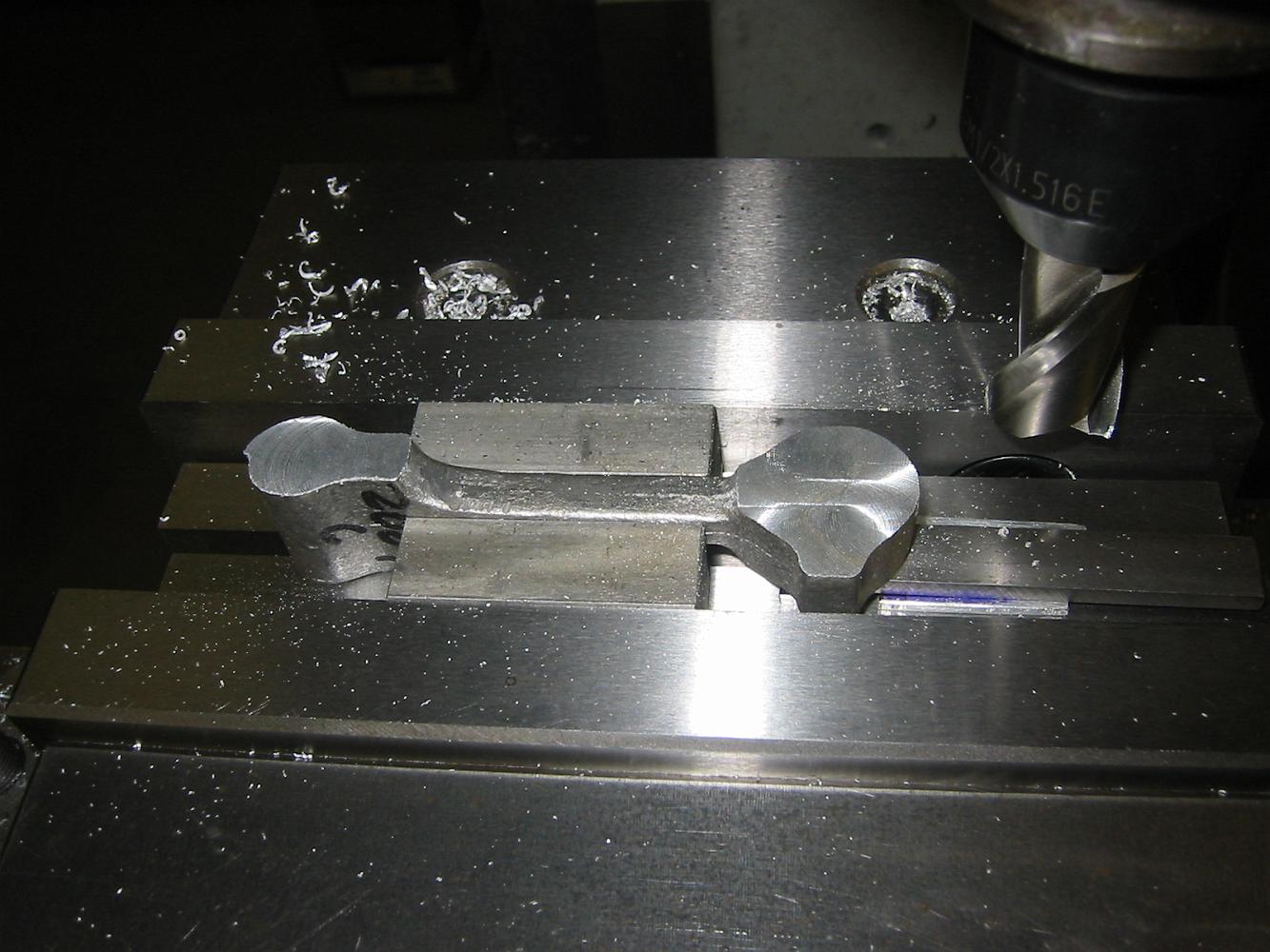
Without any support, the cutter was pulling the rod up and would break it if we continued. We bolt a stop to the inside corner plate which prevented this from…
Leaving the rod end unsupported we not acceptable, so we take and inside corner angle plate to confine the motion. With this setup the end cannot move front to…
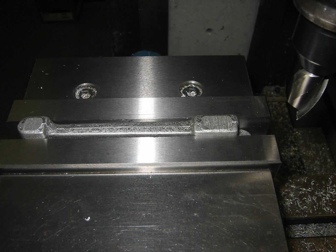
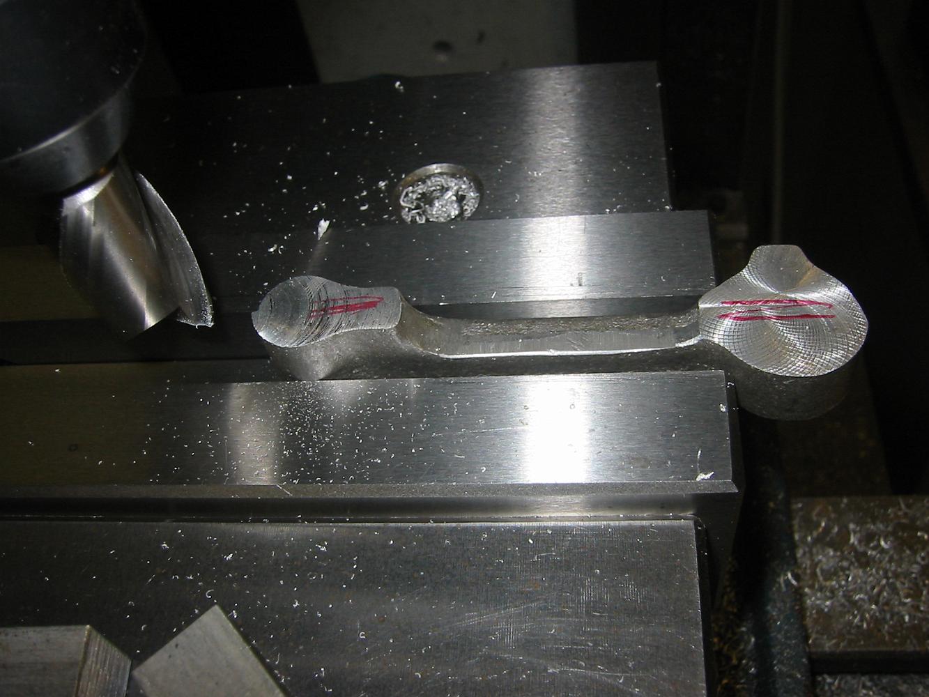
Taking our best guess where the centerline of the Radius rod is inside the casting, we clamp it in the vice, skim cut until we just barely touch the other end.
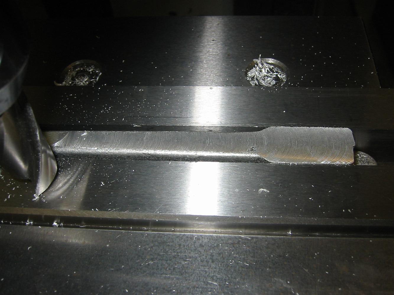
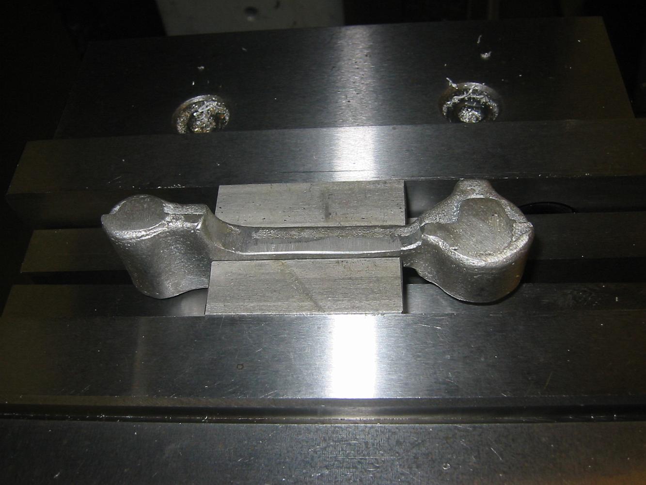
22-Oct-08 There's a lot to be said for machining the valve rods out of solid instead of using castings. For one thing, there is no straight surface anywhere on…
1-Sept-08 Machining the Link Blocks to correct height. This was the last setup for the rotary table.
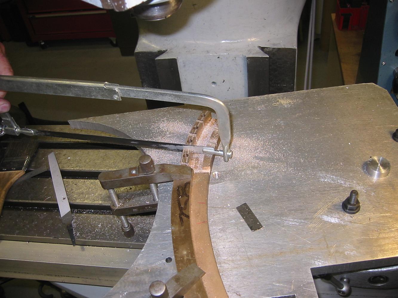
The low-tech method of separating the the link blocks! We'll change setups on the table and finish machine them to size.
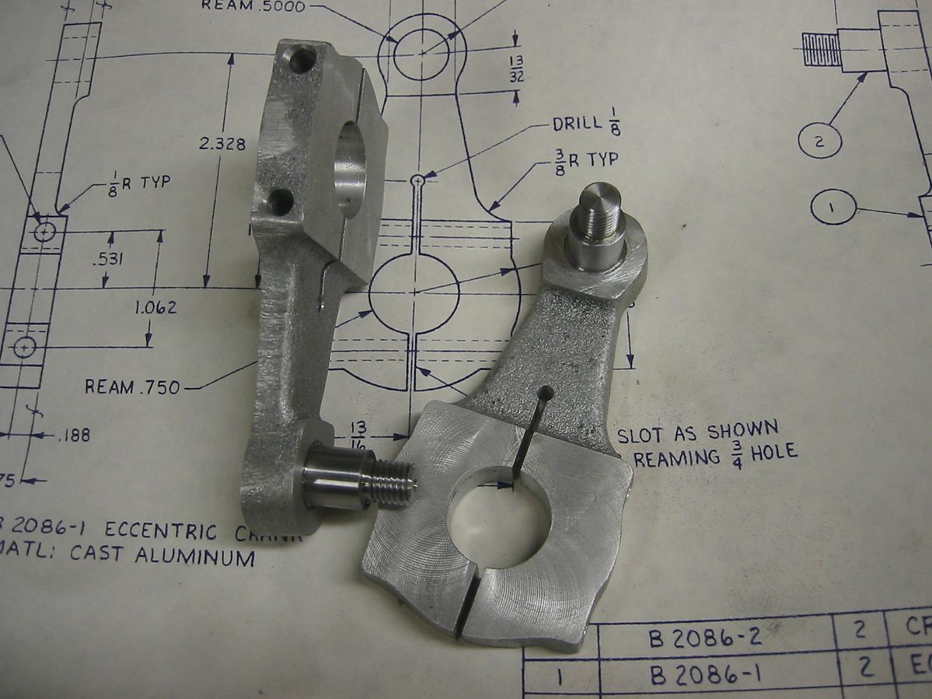
The finished Eccentric Cranks with the pins pressed in. We put the end of the crank on one of the shop lamps to warm it up and make it easier to press the pin…
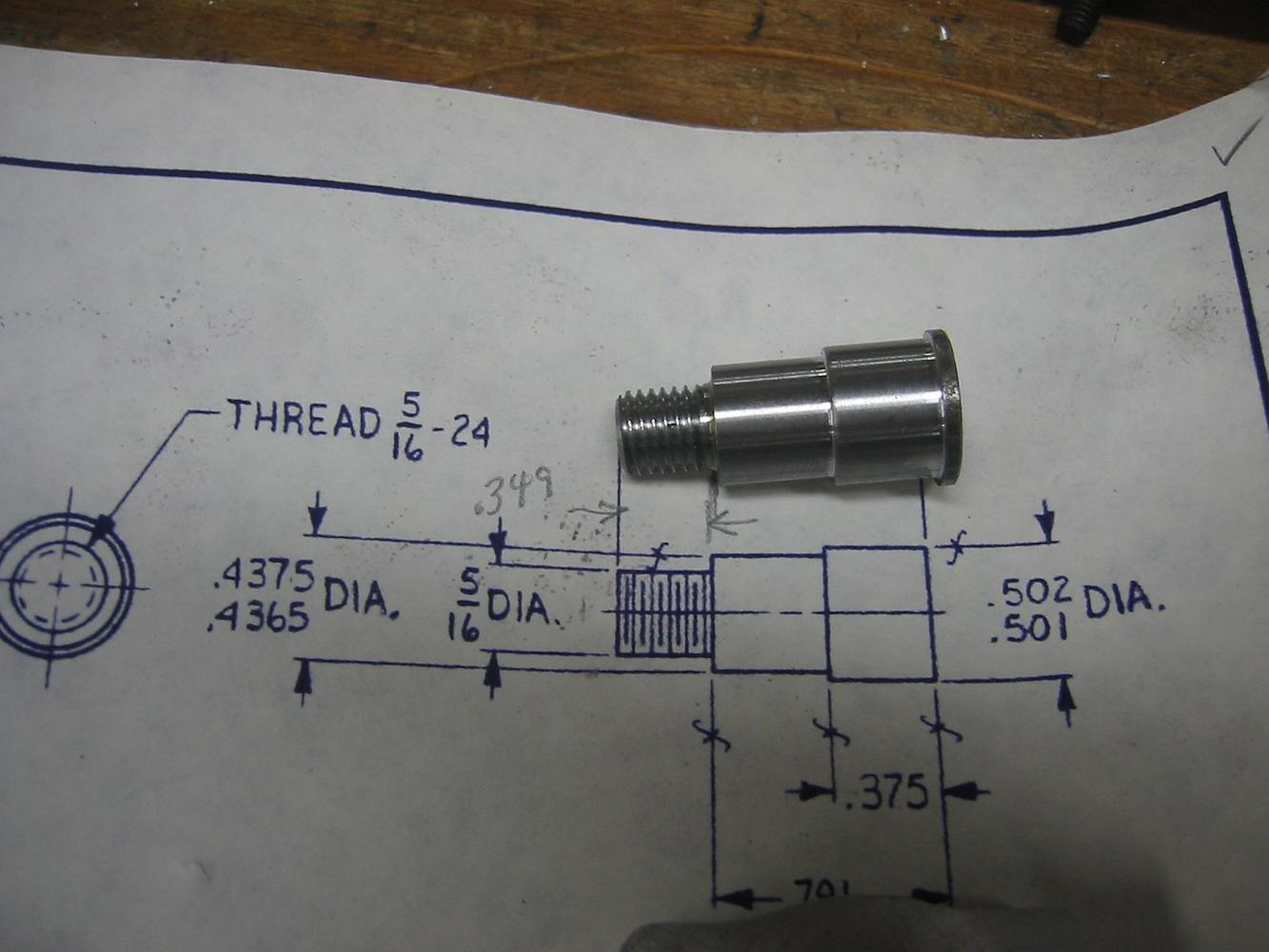
The finished eccentric crank pin. We added a shoulder on the back to keep the pin from being pulled through since it is only held with a very light press fit in…
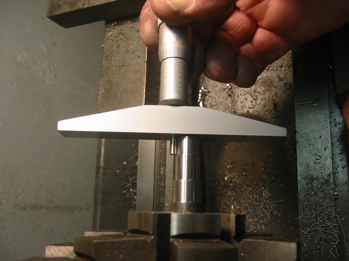
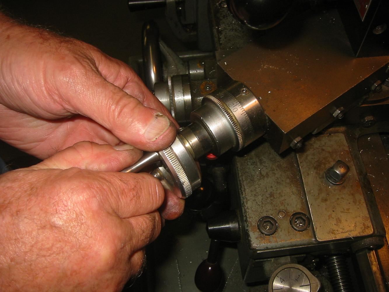
Here's how we we make sure we hit the right length on the pins. Usually we'd use a carriage stop but I don't have a micrometer on mine and who has a .781 long…
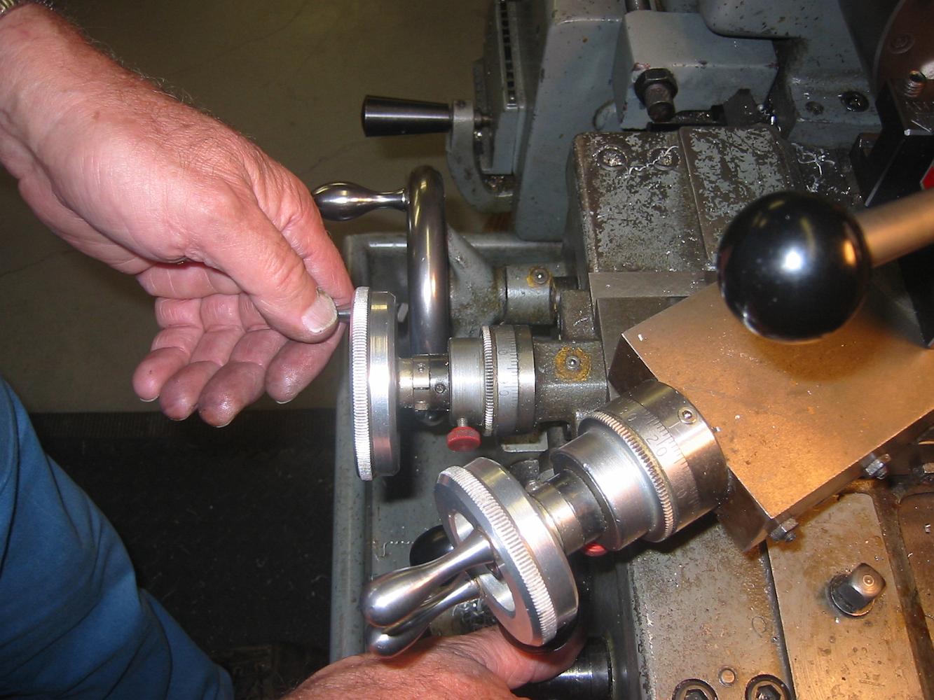
Threading 4 - After returning the crossslide to zero, advance the cross-compound and start the next cut.
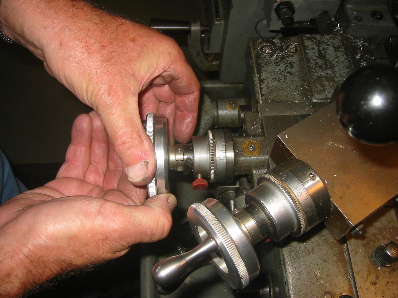
Threading 3: At the end of the cut bring the carriage back to the beginning of the cut, advance the crossslide back to zero.
Threading 2 - a two-handed operation. Left hand on the crossslide to quickly retract, Right hand on the threading lever to disengage at the end of the cut. At…
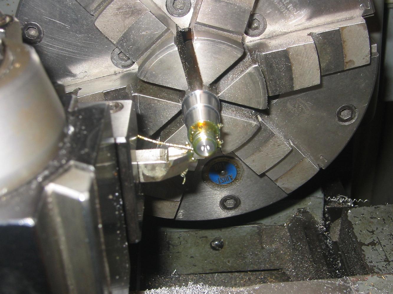
Turning the eccentric pins. I love working that 12L14 leaded steel, it gives such a nice finish on my small lathe. If I had used regular 1018 cold rolled, the…
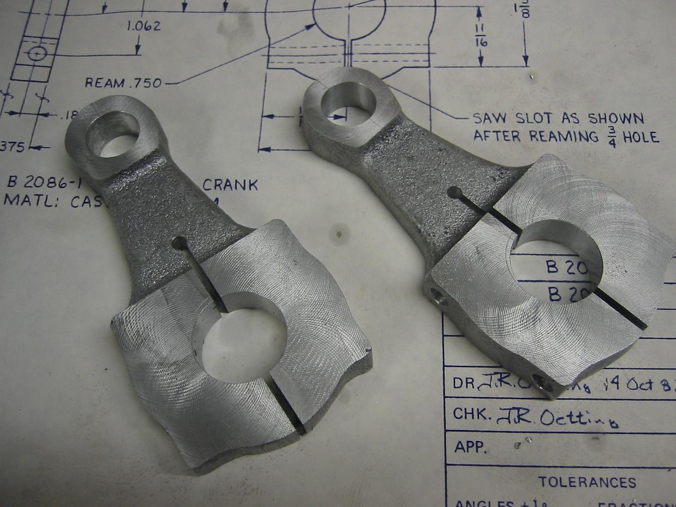
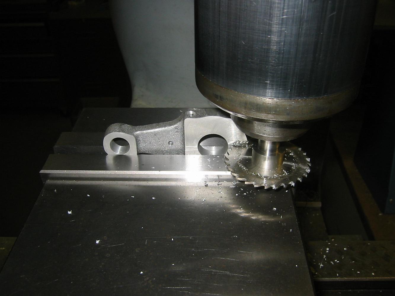
Using a slitting saw to cut the slot in the crank. We had previously lightly scribed the centerline of the holes across the casting and used that line to clamp…
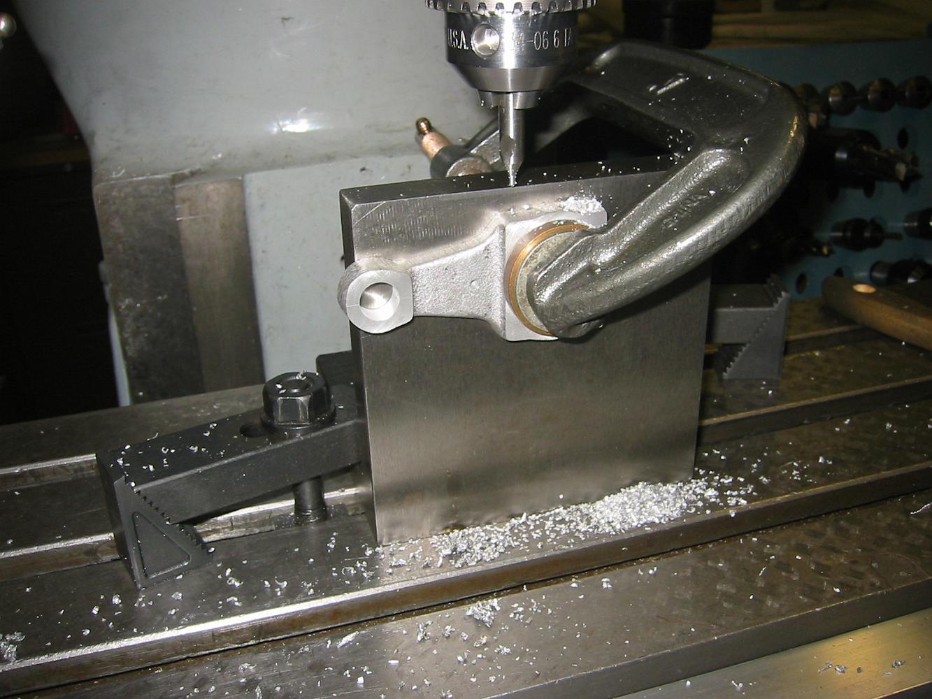
Drilling the clamping holes in the crank with a favorite setup - angle place, locating plug (under the clamp) and C-clamp.
With the crank located on the plug mounted on the angle plate, we use a scriber to check the scribed line and make sure the crank is horizontal before clamping…
The crank on the close-fitting plug, which is bolted to the angle plate. We will use a couple of larger spacers to mount over the bolt/plug and hold the…
The plug mounted on the angle plate. When mounted on the milling table, we can indicate the plug to locate the centerline of the hole.
28-Nov-08 At the end of the night, most of the rods have been drilled and bored. Next to drill the Radius Rod, Eccentric Rod and cut the slots and put the…
How do you hold these castings? With the draft (taper) in them from the moulding process, there isn't a straight spot to start from.
Clamping attempt #1 for the left Tumbling Shaft Lever. This did not have enough support to keep the part from moving under the cutter.
Machining the lever for the engineers side. The problem with this clamping setup is that any twist or differences in height between the two legs results in us…
12-Nov-08 We start work on the Tumbling Shaft Lever. There's no place to hold these castings! Everywhere we want to clamp we have to machine.
Cutting the other side. We are using the end of the vise like a v-block, most of the clamping force is on the left end of the link.
Next it's a simple step to drill and bore the holes. Not seen is the machinist's jack to support the end of the fixture hanging out of the vise.
3-Dec-08. To accurately lay out the holes for the Radius Rod and Eccentric Rod, we build a drill fixture. using a piece of aluminum tooling plate, we machined…
10-Dec-08 Levers with slots! This wraps up another year in the shop, nothing more until after the new year holidays are over.
We had some discussions on how to hold the Eccentric Rod to mill the slot. In the end we decided to just clamp it in the vise and mill the middle away. The risk…
It's hard to hold Combination Lever with an offset in the vise, so a couple of blocks are used to pinch the part in the jaws. Then we mill the slot in a…
Back and forth we go, taking a little more off each time. After we have milled the middle away, we go back and do a finish pass on each side to get the 'ears'…
10-Dec-08 time to cut some slots. The lifting link is short enough to hold in the vise jaws. A quick bump of the cutter a close fitting pin allows us to get a…
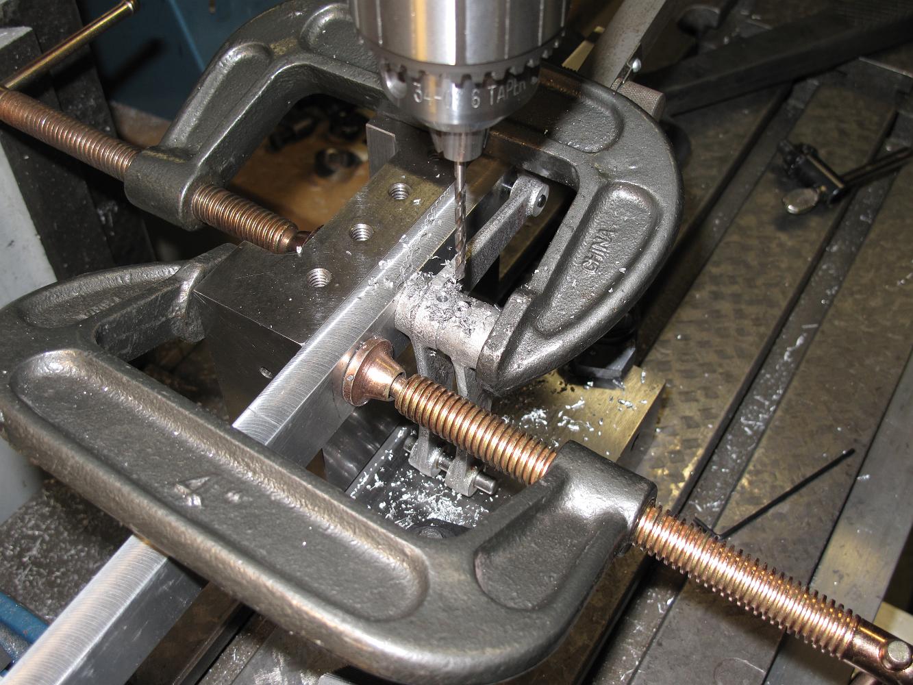
31-Jan-09 Drilling the roll pin holes for the tumbling shaft lifting arms. Reviewing the blueprint notes, we could not see how we could accurately match drill…
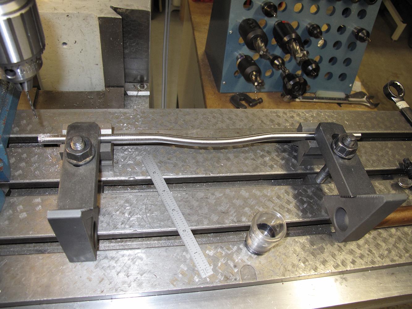
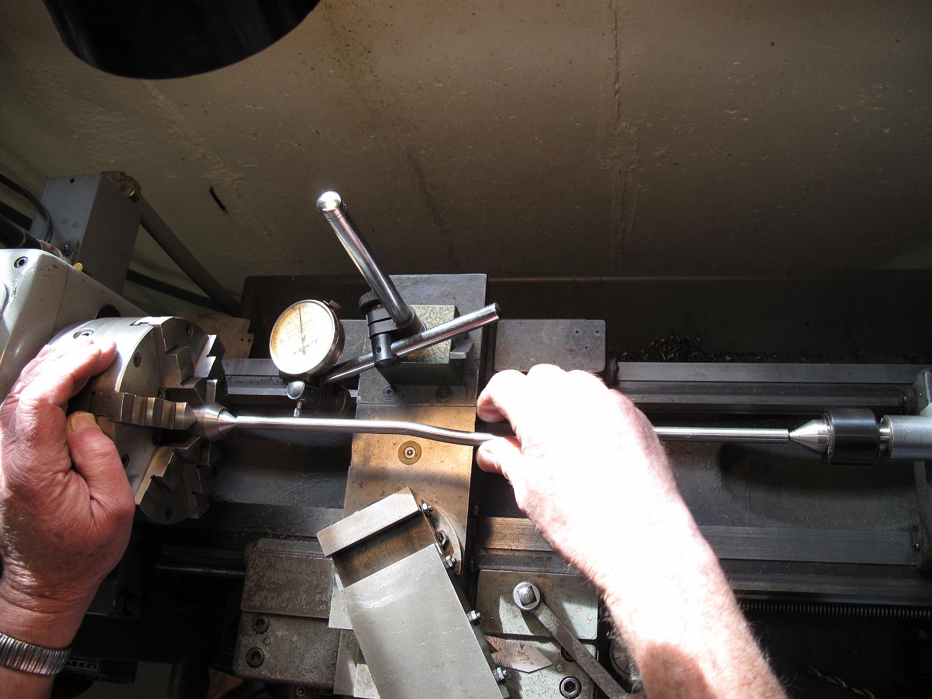
31-Jan-09 With the shaft held between centers (we had drilled center holes in the ends before bending), we use a dial indicator to measure the total indicated…
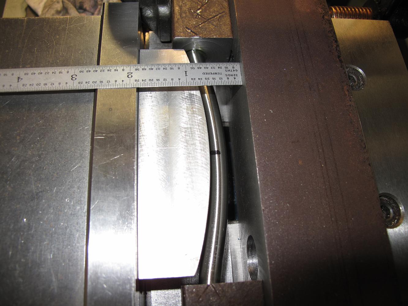
With a guess on how much spring-back to accommodate, we crank the vise down and the bending jig goes to work.
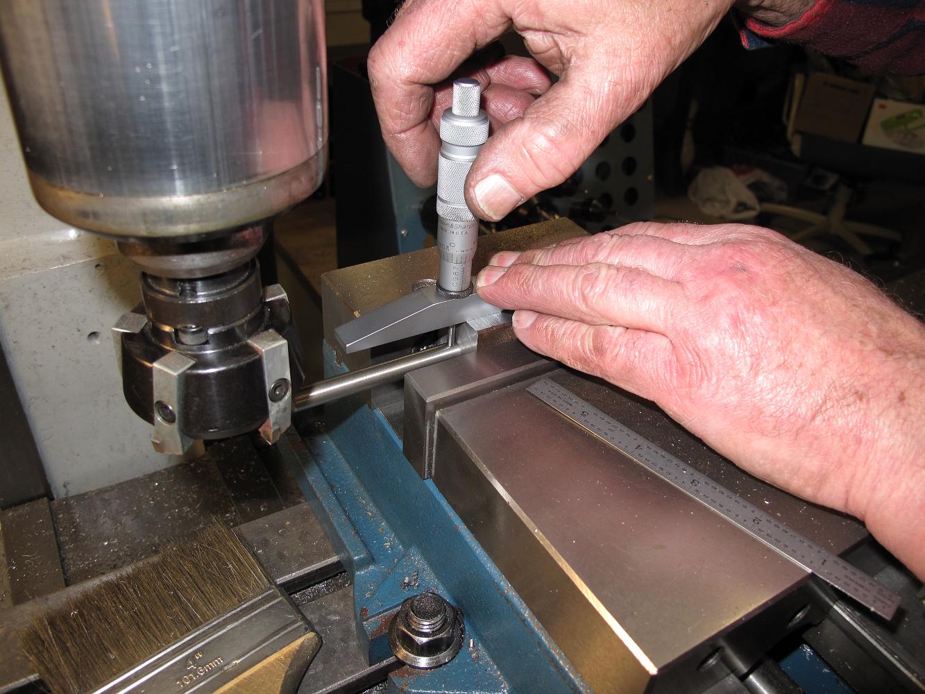
Using a depth mike to measure the depth of the block relative to the hole. We do this on both sides to make sure the machined surface is parallel to the reamed…
Drilling the pilot hole, then we will enlarge the holes and ream to a finish through the block. Deep drilling a hole like this will make you wish for a lever…
The Tumbling Shaft bending jig needs to hold the bar ends in place during the bending operation. We will use two 4" blocks of steel, drilled and reamed to a…
Bill keeps one hand on the carriage crank and the other on the tool holder keeping a tool bit shim from rattling out during the interrupted cut.
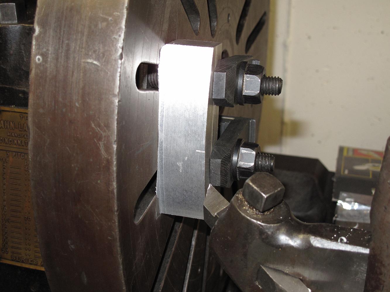
21-Jan-09 The big 1925 Rahn-Larmon cone head lathe is fired up to turn a 12" diameter arc on a piece of aluminum. This will be the bending die for the tumbling…
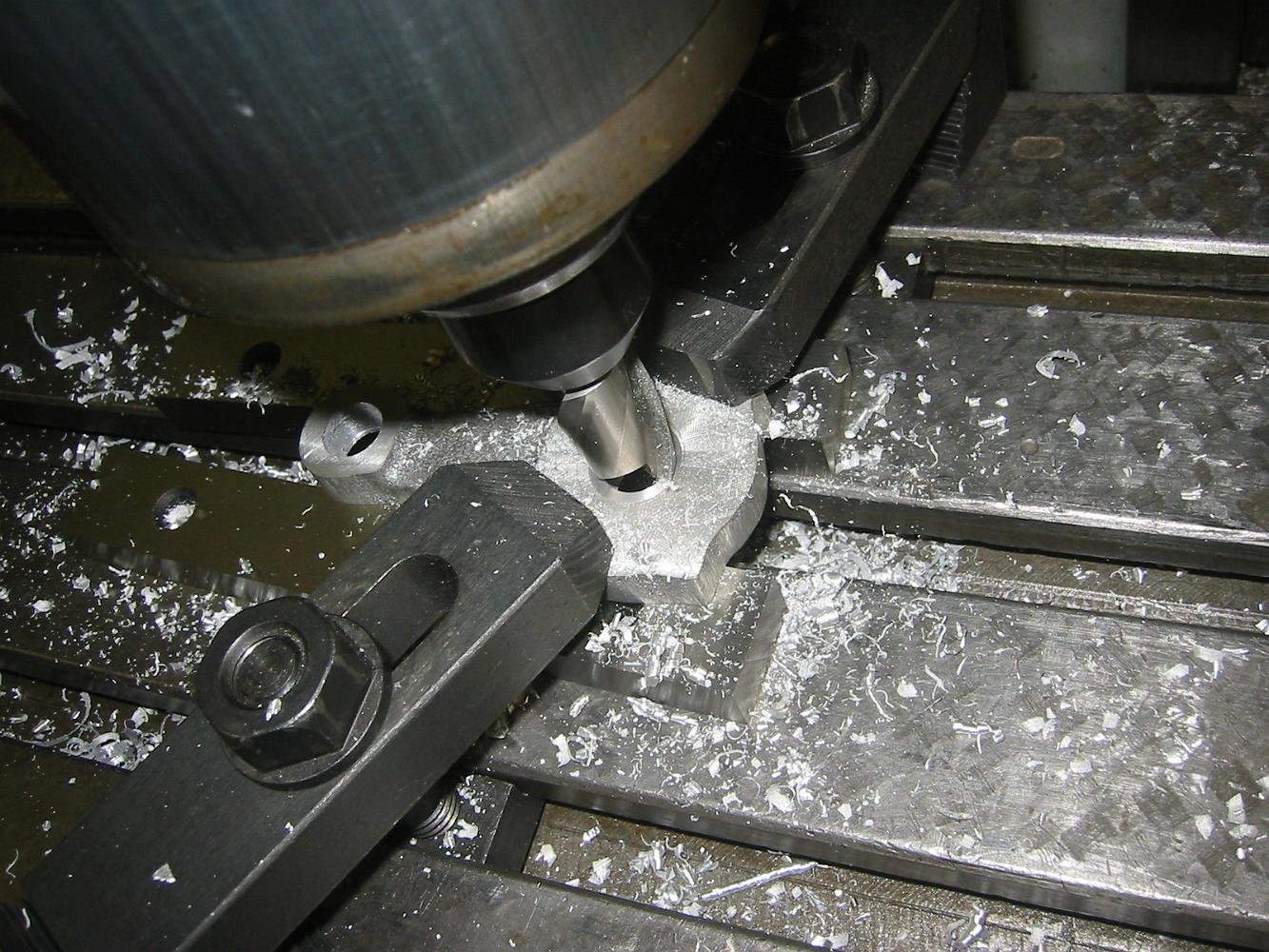
Foregoing the hassle of setting up a rotary table, we clamp a dowel pin in the vise, and making sure to take light cuts and CONVENTIONAL mill only, we rotate…
My eccentric rods were cast as both lefts and rights, and needed to have the 'oil fitting' nub machined off.
Using a small 1/4" adjustable reamer to finish the bushed hole to the correct size. The oil impregnated bronze bushings were .002 oversize (I only wanted .001…
14-Jan-08 Time to drill some oil holes! Using a protractor and eye-ball-that-oughta-do alignment method to put the oil hole near the center of the shaft hole,…
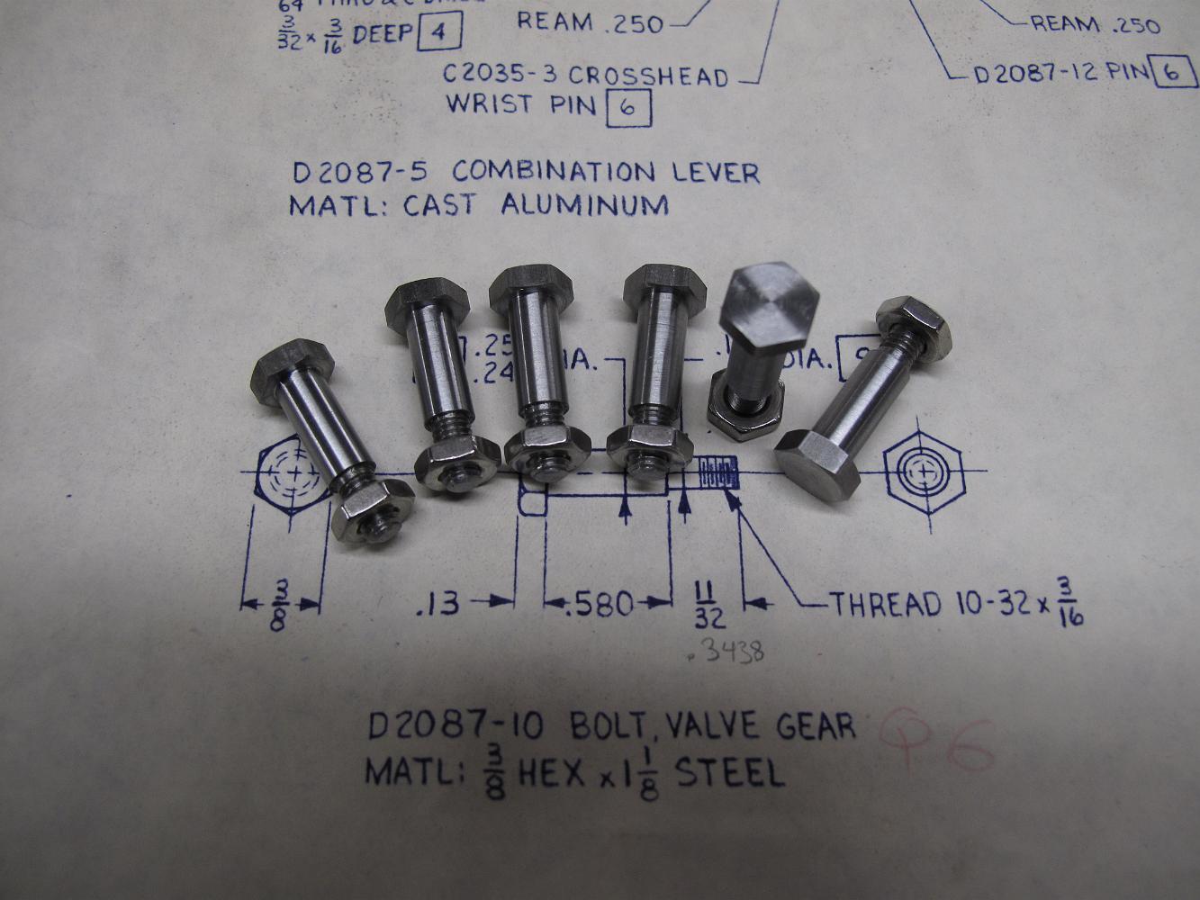
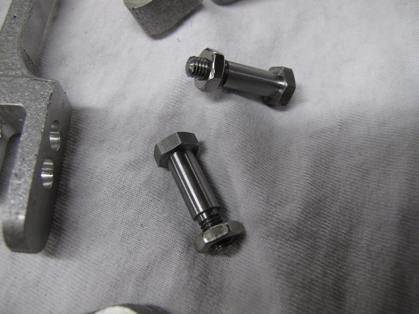
While Bill was making the Tumbling Shaft bending jig, I finished making the six bolts for the valve gear. The quality of what I can make has improved since we…
19-Jan-09 Turning our attention back to the unfinished Tumbling Shaft Levers, we re-use the tooling plate fixture to hold the levers perfectly square. We have…
19-Jan-09 Bill and I have been puzzling how to put that 6" radius bend in the Tumbling Shaft while maintaining concentricity of both ends. We know that not…
The second step to machine the radius rod is to put a spacer in the ends of the finished 'ears' which is exactly the same width as the slot opening. We then…