Up one level Neidrauer Adventures and Photo Album » Building a Live Steam Locomotive - the Mikado Project » Section 10 - Drive Rods
Section 10 - Drive Rods
Completed! Drive Rods. Main, Side and Intermediate rods. Jan-June 2008

Previous page At last page 33-55 (of 55 found)
  The bored connecting rod hole.  23-Apr-08 Centering the connecting rod to bore the other end. We've moved the blueprint distance from the drilled end to the other end and are centering the other hole left to right.  The setup for boring the Intermediate rod.  17-Apr-08 Main rod with bearing installed.  Cutting the pressed-in bearing to size.  We later decided that cutting the bearing to size THEN pressing it in was a better approach.  Here's what we ended up with: A very flat thick washer (brass in this case) 
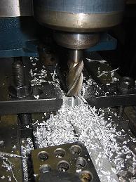
on the table, lifting the rod off the table with clamps holding it tight.  17 Apr 08 Preparing to bore the Main rod. ?How to hold the rod?  Milling the bearing ends to the finished size.  This clamping solution turned out to be the best, the parts were solidly held to the table, without introducing any more twist or taper relative to the other finished side.  The side rods with the clamping screw holes.  Using a cutter which has been profiled to drill and countersink a 1/4-20 hole in one operation.  Previous clamping attempts did not work. We needed a way to hold the bearing ends of the rod down to the table which allowed us to machine the very same spot at the same time. Well, we have to bore a hole for the bearings anyway, so let's put in a smaller hole and use a screw as a clamp.  Since we have four rods to machine, we clamp a v-block to the table which allows us to indicate and move the head over the centerline of the hole for all parts.  With the one machined side down on the table, we try to clamp them down to machine the other side.  The  2-Apr-08 On to the side rods. Another set of castings, more challenges.  Where to start? Using the center web as a rough guide, we clamp the rods on the vice and rough machine the bearing ends.  With the bearing ends machined to finished size, the tabs are then finished machined.  With the part clamped  26-Mar-08. The Intermediate Drive Rods are another pair of challenging castings. The thin tabs at either end were warped and there was a twist between either end.  Such is the nature of castings.  With a rough finish all around, but only a few surfaces marked on the print to be machined, holding the parts is yet again a challenge.  After taking a light cut on both tabs, Bill clamps them  11-Mar-08 We start a new Section!  Like all castings, the question is where to start - nothing is smooth or straight.  11-Mar-08 Rough machining the Drive Rod.  Castings are a pain for work with, especially something like this where the surface you want to clamp on is also the suface you want to machine. And all the dimensions are around the centerline of the part, but like all castings, things are bent, warped or twisted. Clamping on the 'webbed' portion of the rod causes the ends to flex (see shims under part to compensate).  Probably a better method would have been to drill a through-hole to screw the part to the table and machined around the screw.  See connecting rods pictures.  Trying to compensate and adjust for the twist in the casting and clamp with a neutral impact.  We machined only one side first to get reference surfaces.  With a machined, and hopefully true, side, we clamp it to the table to machine the other side.  Since we could not clamp over the machined portion, which would have been ideal, we spent a lot of time fussing with the clamps to hold the part without moving the ends to be machined around. It worked, sorta. We ended up with tapered surfaces when we measured across both machined sides.