Up one level Neidrauer Live Steam Locomotives Photo Albums » Building a Live Steam Locomotive - the Mikado Project » Section 18 - Tender
Section 18 - Tender
Lessons in steel tank coatings. 2015 Added the "doghouse" - the brakeman's shack to the tender deck, a unique Frisco detail, and backup light. 2014 - Finished over the winter and in service! Some detail work remains. The July 2013 Assembly continues, riveting and welding are in progress. I have already learned one lesson: Cut the tender frame to length AFTER the tank is made. Maybe you will do better than I did, but my tank is a about 1" shorter than planned making accurate bends in the sheet sides is hard! After using a borrowed tender for the first fire up of the locomotive, all attention is turned to fabricating one this winter. November 2012 - raw stock for Tender Frame cut. Steel side sheets for tender tank laser cut. Fiberglass Tender received 2003. June 2009 - I decide to make a tender instead of using the fiberglass one since the 3 axle trucks I have will not fit under the frame.

Previous page Next page 65-128 (of 164 found)
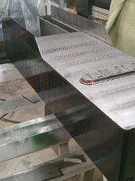
IMG_5366 13-Jan-2014 Giving up on the rotary table to round the ends of the hatch, I go low tech and clamp the part to a sawhorse and use the sanding wheel on the angle grinder to round the ends. IMG_5371 18-Jan-2018 With the tender frame welded up, the frame deck can be trimmed to the finished size. IMG_5372 18-Jan-2014 Simple outboard support for the tender frame deck, and adjustable height bench chair. IMG_5375 20-Jan-2014 Using the angle plate and cutoff saw, the right-hand hatch cover is cut. IMG_5376 20-Jan-2014 Having failed to make enough allowances for saw cuts in the hatch cover, I use the thinnest blade I am comfortable with to cut the left, right and center pieces. IMG_5377 20-Jan-2014 The thin 0.040 saw made a Bang! Crunch! noise and faster than I could react half the saw broke apart. I was using cutting oil, small infeeds and a slow cutting speed, but it was not enough. I did not have any other saws this thin. Amazingly I was able to finish the cuts with this broken saw, using very very light cuts. IMG_5378 20-Jan-2014 I had to add an anti-vibration support to reduce the amount of spring the part had in it from this suspect setup. IMG_5379 20-Jan-2014 I fabricate a bending die for the center hatch cover which lays over the left and right covers. IMG_5380 20-Jan-2014 Bottom half of bending die, laid out with best accuracy I can manage. IMG_5382 23-Jan-2014 Top half of bending die being machined. IMG_5383 24-Jan-2014 Upper and lower halves of the die completed and dowel pins pushed in with the press. I put the two halves together and they fit - yea! IMG_5384 24-Jan-2014 Second bending try in the hydraulic press and pump the jack handle until it won't go anymore and the results are better. IMG_5386 24-Jan-2014 Bend test with a scrap piece does not show the IMG_5389 25-Jan-2014 Finished center hatch lid IMG_5390 25-Jan-2014 Finished center hatch lid in the die. Note the relief cut in the bottom die to allow the first bend clearance. IMG_5392 27-Jan-2014 Another bending die! This one to make the hatch handles. IMG_5393 27-Jan-2014 Another bending die! This one to make the hatch handles. IMG_5394 27-Jan-2014 Hatch handles are bend in the die. One side is extra long to give me something to hand onto for the later drilling operations. IMG_5397 1-Feb-2014 Contemplating how I am going to make the strap hinges, using the Frisco 1522 tender hatch picture as a guide. IMG_5401 3-Feb-2014 Taking a tip from master builder Kozo Hiraoka, I fabricate the butt side of the hinges with a silver solder operation. IMG_5402 3-Feb-2014 The silver soldered portion of the strap hinges - a length of flat stock and turned stock each. IMG_5404 3-Feb-2014 Hinges after silver soldering. Close examination shows more practice is required to make a professional looking joint. IMG_5408 4-Feb-2014 A small carbide mill and gentle cuts puts the slot into the hinges. IMG_5410 4-Feb-2014 The setup to produce six interchangeable hinges: vise stop for location, and a parallel with a down pin (I had to use a drill bit) to set the height. IMG_5411 4-Feb-2014 The result: six hinges almost interchangeable. Labeled for best fit with each other. IMG_5413 10-Feb-2014 Drilling the rivet hole in the butt part of the hinge, using a piece of wood with a close fitting slot to hold the parts. IMG_5415 10-Feb-2014 Trial fitting the hinges on the hatch frame and covers. IMG_5417 15-Feb-2014 The tender trucks have progressed to the point that we see the bolster mount design called for by the blueprints will not work for us. I work on undoing the welding with a carbide mill. IMG_5420 15-Feb-2014 Welding the kingpin boss to the frame plate. IMG_5431 17-Feb-2014 My second attempt to braze this joint also failed, so a bit of weld from the MIG welder is applied. I will have to machine the extra away. IMG_5432 17-Feb-2014 Riveting the hinge butts to the frame broke the poor braze weld joints, so I weld them with the MIG wire feed welder. IMG_5433 17-Feb-2014 With the trucks under the tender, we discover the coupler pocket is too high and does not meet IBLS standards. We will modify the coupler pocket to lower it. IMG_5434 17-Feb-2014 Modifying the coupler pocket also means modifying the bumper beam. IMG_5436 17-Feb-2014 During the riveting process, one of the ears of the hinge came off, so I silver soldered it back together and used the end of a drill to help alignment. Yes, I soldered the drill to the part. Some careful machining with a carbide mill cut the drill out. IMG_5437 17-Feb-2014 More progress, the hinge butt have been riveted to the hatch frame, and the straps drilled for the rivets. IMG_5438 22-Feb-2014 Tender rear bumper modifications: spacer blocks added to the coupler pocket. IMG_5439 22-Feb-2014 Tender rear bumper modifications: spacer blocks for the coupler pocket. IMG_5440 22-Feb-2014 Height check of the modifications: Pass. IMG_5441 22-Feb-2014 Height check of the drawbar pocket with the new front bumper beam. We do not have a way to weld aluminum and do not trust mechanical fasteners for this connection. We could not figure out how to modify the original one and retain the drawbar pin, so we made a new one. IMG_5442 24-Feb-2014 Bill makes up a quick disconnect drawbar pin keeper. This is our own design. IMG_5443 24-Feb-2014 I finish putting the rivets in tender deck. I am able to do two lines each day before I get tired out and stop. IMG_5445 1-Mar-2014 The truck mount plate is welded to the frame, along with the kingpin bolt. IMG_5449 1-Mar-2014 The bending jig is employed to hold the parts for drilling the rivet holes. IMG_5450 1-Mar-2014 Now that the frame is finished and front and rear bumpers installed, the front tank hold down brackets can be installed in the correct position. IMG_5454 3-Mar-2014 Machine capacity check - how to drill and tap holes in the end of a 16 IMG_5455 3-Mar-2014 The table is all the way down to give us the height needed to drill and tap a hole in the end of the beam for the footpegs IMG_5456 3-Mar-2014 The hinge straps have been riveted to the lid covers and everything still works! IMAG0308 4-Mar-2014 I am nearly done with all the riveting, and with the tender top. IMG_5458 3-Mar-2014 I am so excited to see the hatch at this point of assembly. IMG_5459 8-Mar-2014 Bill makes a pair of footpegs out of some soft 12L18 leaded mild steel. The knurling tool calls for flood coolant, which I do not have, and one of the knurls starts squeaking then siezes up, ruining one part of the knurl. Fortunately we are able to clean up the knurl and pin and use it dribbling cutting fluid on it. IMG_5460 8-Feb-2014 I spend some time with the hand drill and several drill bits to get the tender deck ready for hatch installation. IMG_5461 8-Mar-2014 Proud result of an evenings labor: the tender hatch is riveted to the deck. IMG_5465 10-Mar-2014 Adapting the lathe to be a horizontal mill. We clamped the tender frame to the carriage, shimmed up with blocks and spacers to the correct height, and supported the other end of the frame using a level to make it true. IMG_5466 10-Mar-2014 Milling larger holes in the tender frame to accommodate the water valve fittings. We did not have a way to hold the frame on end - the Mill certainly is not tall enough, so we adapted the lathe to be a horizontal mill. IMG_5468 10-Mar-2014 The enlarged hole for the water valve plumbing. We had to move the hole over, closer to the outside frame. IMG_5469 15-Mar-2014 Laying out the plumbing connections and doing a design-on-the-fly assembly. IMG_5470 15-Mar-2014 Having discovered the bonnet on the ball valves will have to stick up into the tender, I am force to modify the tender bottom. I remove the valve extension tubes previously welded to the bottom with a hole saw. IMG_5473 17-Mar-2014 Pipe elbows installed in the tender bottom, Tender deck test fitted. IMG_5474 17-Mar-2014 New 1 IMG_5477 24-Mar-2014 Once again, the mill table is stripped of the vise and the Tender deck is bolted down for modification - in this case, enlargement of the water control valve openings for the new control rod pipes. IMG_5482 5-Apr-2014 Look what arrived! The fabricated fuel tank. All stainless steel construction, 9 gallon capacity. IMG_5484 7-Apr-2014 The painted tender frame upside down on the bottom of the tender to locate the brackets which will hold the hard piping and valves in place. I weld the blocks to the frame. IMG_5486 7-Apr-2014 Fit check: oil tank on tenders, valve control handles do not interfere. IMG_5491 12-Apr-2014 Time to waterproof the tender. I am using gas tank liner brand
Page 2 of 3 Next page